
OLIMEX A10-OLX-LIME Инструкция по эксплуатации онлайн
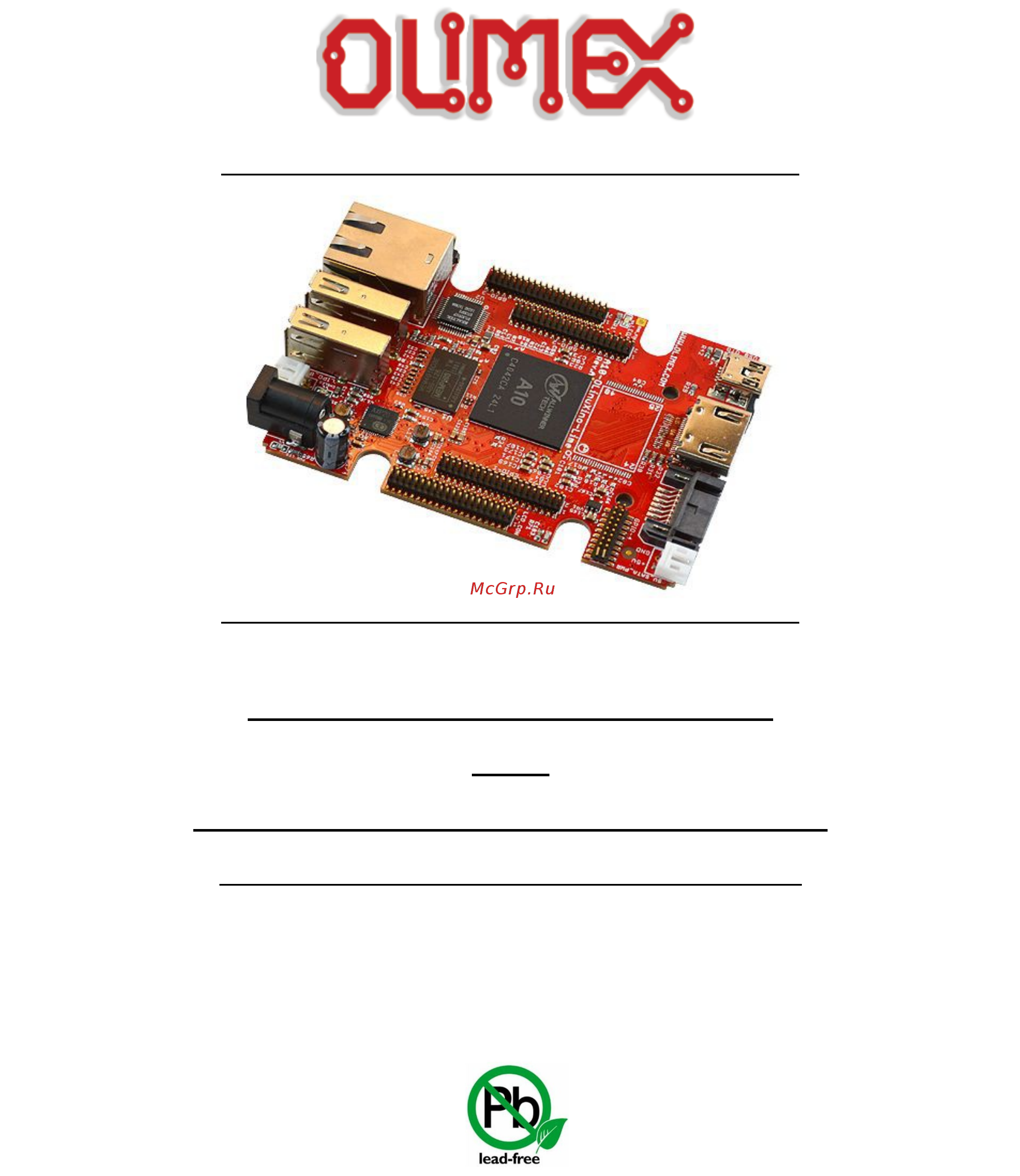
A10-OLINUXINO-LIME
and
A10-OLINUXINO-LIME-4GB
Open-source single-board Android/Linux mini-computer
USER’S MANUAL
Revision H, March 2015
Designed by OLIMEX Ltd, 2015
All boards produced by Olimex LTD are ROHS compliant
Содержание
- Disclaimer 2
- There is no warranty for the design materials and the components used to create a10 olinuxino lime and a10 olinuxino lime 4gb they are considered suitable only for respectively a10 olinuxino lime or a10 olinuxino lime 4gb 2
- Chapter 1 overview 5 3
- Chapter 2 setting up the olinuxino board 8 3
- Chapter 3 a10 olinuxino lime board description 16 3
- Chapter 4 the allwinner a10 microcontroller 18 3
- Chapter 5 control circuity 20 3
- Chapter 6 connectors and pinout 21 3
- Disclaimer 2 3
- Table of contents 3
- Chapter 7 schematics 38 4
- Chapter 8 revision history and support 40 4
- Chapter 1 overview 5
- Features 5
- Introduction to the chapter 5
- Board variants 6
- Board version used in the manual 6
- Target market and purpose of the board 6
- Document organization 7
- Chapter 2 setting up the olinuxino board 8
- Electrostatic and electrical polarity warning 8
- Introduction to the chapter 8
- Requirements 8
- Powering the board 10
- Button functions 11
- Changing the default image resolution 11
- Connecting and calibrating a display 12
- Android calibration 13
- Debian calibration 13
- Gpio under debian 13
- I2c and spi under debian 14
- Software support 15
- Chapter 3 a10 olinuxino lime board description 16
- Introduction to the chapter 16
- Layout top view 16
- At the bottom are located mainly the buttons and microsd card connector 17
- Layout bottom view 17
- You should be careful of the surface that you use to place the board 17
- Chapter 4 the allwinner a10 microcontroller 18
- Introduction to the chapter 18
- The processor 18
- Chapter 5 control circuity 20
- Clocks 20
- Introduction to the chapter 20
- Power supply circuit 20
- Chapter 6 connectors and pinout 21
- Communication with lime 21
- Introduction to the chapter 21
- Uart0 interface 21
- Microsd card connector 22
- Sd mmc1 slot 22
- Additionally there are the wp and cp switches that are responsible respectively for sensing whether the card is locked for reading and whether there is a card inserted 23
- More info about the power supply can be found in chapter 5 of this manual 23
- Pwr jack 23
- The power jack used is the typical dc barrel jack one used by olimex 2 6 9 mm in most of our products more information about the exact component might be found here https www olimex com wiki pwrjack 23
- You should provide 5 volts direct current and the required current may vary depending on the peripherals connected to the board the power supply you use should be capable of providing at least 1a of current 23
- Additionally pb9 ph7_gpio jumper controls which of the two ports pb9 or ph7 should be lead out to pin 9 of gpio3 connector for easier access by default this jumper is in ph7_gpio position and ph7 is lead to pin 9 of gpio3 24
- Please note that the usb0 drv pin c12 port b9 is multiplexed with the i2s_do1 signal if you are going to use the i2s audio interface then you would probably need to change the position of the smt jumper pb9 ph7_usb which by default connects usb_otg to the pb9 this operation would require cutting between the pads of the default position with a very sharp object and then soldering the pads of the other position together doing so you would be able to use both the usb_otg via port ph7 this time and the i2s interface 24
- The main way of changing the firmware image located on the nand of a10 olinuxino lime 4gb is via the usb otg connector how to change the firmware is explained after the hardware details the part of the schematic related to the usb_otg is shown below 24
- The sy6280 responsible for the usb_otg is enabled by usb0 drv processor pin c12 port b9 thus the usb_otg is also controlled by the same signal 24
- The usb_otg features low loss power distribution switch sy6280 which protects the board in case the devices you have plugged to the usb_otg attempt to draw more current than 523ma combined the maximum current available on the 5v usb_otg is exactly 523ma 24
- Usb_otg connector 24
- Ethernet 26
- The gnd is common for both levels of the usb_host 26
- The lan connectivity is handled by realtek s rtl8201cp some of the features of this 10 100mbit controller are 26
- The lime board is equipped with a standard rj45 ethernet connector at the top of the board that allows you to access local network via an ethernet cable 26
- The part of the schematic related to the usb_host connectors is listed below 26
- The sy6280 responsible for the usb_host1 is enabled by usb0 drv1 processor pin a4 26
- The sy6280 responsible for the usb_host2 is enabled by usb0 drv2 processor pin a5 26
- There are two usb host connector featured on the board they are called usb_host1 and usb_host2 each of them has own connector both situated near the ethernet connector each of connector has own low loss power distribution switch sy6280 which protects the board in case the devices you have plugged to the board try to draw more current than 523ma combined the maximum current available on each of the usb hosts is exactly 523ma 26
- Usb_host connectors 26
- The rj45 connector has a small yellow and a small built in leds and they are described below 28
- Hdmi connector 29
- Note that there are different linux images depending whether the hdmi tv works at 50hz or 60hz refresh rate if you board runs android there is a specific option to set the appropriate hdmi output 29
- Pin 14 of the hdmi is not mandatory in hdmi 1 1 c it is reserved pin in hdmi 1 it is optional 29
- The part of the schematic that describes the hdmi module is shown below 29
- For more information please visit https www olimex com products components cables sata cable set 30
- Pay note the two jumpers 5v_e_sata and pc3 pb located at the bottom of the board under the hdmi connector the first one 5v_e_sata is open by default because the board has software control of the powering for the hard disk if you close 5v_e_sata there would always be 5v at the 5v_sata_pwr connector 30
- Sata connector and power 30
- The part of the schematic describing the sata module is shown below 30
- There is a 5v_sata_pwr connector that is suitable for powering 5v hard disks trough the board to keep the low form factor we have placed the small jst connector 30
- Which pin does the software control of the sata powering is determined by the position of the pc3 pb8 jumper by default pc3 is used 30
- You can make an adapter cable accordingly the other options is to check the sata cable set that we have available 30
- Gpio 1 general purpose input output 40pin connector 31
- Gpio ports 31
- A general advice for easier use of the microphone headphone and vga interfaces of a10 olinuxino lime is to take a look at the schematics of another board with those interfaces already installed for example those are present in a20 olinuxino micro inspect the schematic carefully 32
- If you inspect the schematics of a board with vga connector like a20 olinuxino micro carefully you would notice that there are two extra transistors on the synchronization lines those are transistors meant to shift the levels to 5v the 3 v levels from the processor might work but the standard requires 5v levels of vsync and hsync however if you lead the signals to a 6 pin header like the one on the a20 board you might use the cable for the a20 olinuxino micro called a20 vga cable the 6 signals needed are the 5 signals mentioned about plus gnd 32
- Lcd_vsync ac9 and lcd_hsync ab9 32
- The light blue boxes represent the pins related to microphone input the yellow boxes represent pins related to the headphone output the pale green boxes represent the pins related to alternative video output there are more located on the lcd connector 32
- The signal layout is described below 32
- Gpio 2 general purpose input output 40pin connector 33
- The gpio pins are led out on a separate 40pin connecter they allow the user to attach additional hardware check readings or perform hardware debug the gpio 2 connector numbers are printed at the bottom of the board for your convenience 33
- Gpio 3 general purpose input output 40pin connector 34
- Gpio 4 connector features the rest of the signals available and few additional signals that might need testing 34
- Gpio 4 general purpose input output 20pin connector 34
- Important to use android with display or resolution different than hdmi and 1024 600 default settings you need to upload new android image to the board these images are available here https www olimex com wiki a10 olinuxino lime using an operating system nand flash 35
- Important you need additional 40pin ribbon cable to connect an olimex display and the lcd_con 35
- In debian linux you would need to start a start a shell script to change the built in the image resolution settings start it with change_display_a10_lime sh and follow the instructions please refer to chapter 2 changing the default image resolution for more information 35
- Lcd_con 40pin connector 35
- The lcd connector is suitable for a number of olimex displays and touchscreen panels with different native resolution the smallest available is the 4 one called lcd olinuxino 4 ts with native screen resolution of 480 272 through the 7 one named lcd olinuxino 7ts with 800 480 to the 1024 600 10 lcd olinuxino 10ts 35
- The lcd_con pins are led out on a separate 40pin connecter for the ease of connecting an lcd we have tested the ability of the board to interact with such a display they allow the user to attach additional hardware check readings or perform hardware debug 35
- Jumper description 36
- Please note that most the jumpers on the board are smt type if you feel insecure of your soldering cutting technique it is better not to try to adjust the jumpers since it is possible to damage the board 36
- Additional hardware components 37
- Chapter 7 schematics 38
- Eagle schematic 38
- Introduction to the chapter 38
- Note that all dimensions are in mils 39
- Physical dimensions 39
- Chapter 8 revision history and support 40
- Document revision 40
- In this chapter you will find the current and the previous version of the document you are reading also the web page for your device is listed be sure to check it after a purchase for the latest available updates and examples 40
- Introduction to the chapter 40
- Board revision 41
- Remember to check the schematics and the board design files to compare the differences 41
- Useful web links and purchase codes 42
- Frequently asked questions 43
- For product support hardware information and error reports mail to support olimex com all document or hardware feedback is welcome note that we are primarily a hardware company and our software support is limited please consider reading the paragraph below about the warranty of olimex products 45
- Olimex 2015 a10 olinuxino lime user s manual 45
- Page 45 of 45 45
- Product support 45
- The full text might be found at https www olimex com wiki gtc warranty for future reference 45
Похожие устройства
- OLIMEX A10-LIME-N8GB Инструкция по эксплуатации
- OLIMEX A13-OLX-MICRO Инструкция по эксплуатации
- OLIMEX A13-OLX-WIFI Инструкция по эксплуатации
- OLIMEX A13-SOM-256 Инструкция по эксплуатации
- OLIMEX A13-SOM-512 Инструкция по эксплуатации
- OLIMEX A20-OLX-LIME Инструкция по эксплуатации
- OLIMEX A20-OLX-LIME2 Инструкция по эксплуатации
- OLIMEX A20-LIME2-E16GS16 Инструкция по эксплуатации
- OLIMEX A20-LIME2-E4GS16 Инструкция по эксплуатации
- OLIMEX A20-LIME2-N8GB Инструкция по эксплуатации
- OLIMEX A20-LIME2-S16 Инструкция по эксплуатации
- OLIMEX A20-LIME-E16GS16 Инструкция по эксплуатации
- OLIMEX A20-LIME-E4GS16 Инструкция по эксплуатации
- OLIMEX A20-LIME-N8G Инструкция по эксплуатации
- OLIMEX A20-LIME-S16 Инструкция по эксплуатации
- OLIMEX A20-OLX-MICRO Инструкция по эксплуатации
- OLIMEX A20-OLX-MICRO-4GB Инструкция по эксплуатации
- OLIMEX A20-MICRO-E16GS16 Инструкция по эксплуатации
- OLIMEX A20-MICRO-E4GS16 Инструкция по эксплуатации
- OLIMEX A20-MICRO-N8G Инструкция по эксплуатации