
Daikin ZH7SLF Инструкция по эксплуатации IV ver онлайн
IV
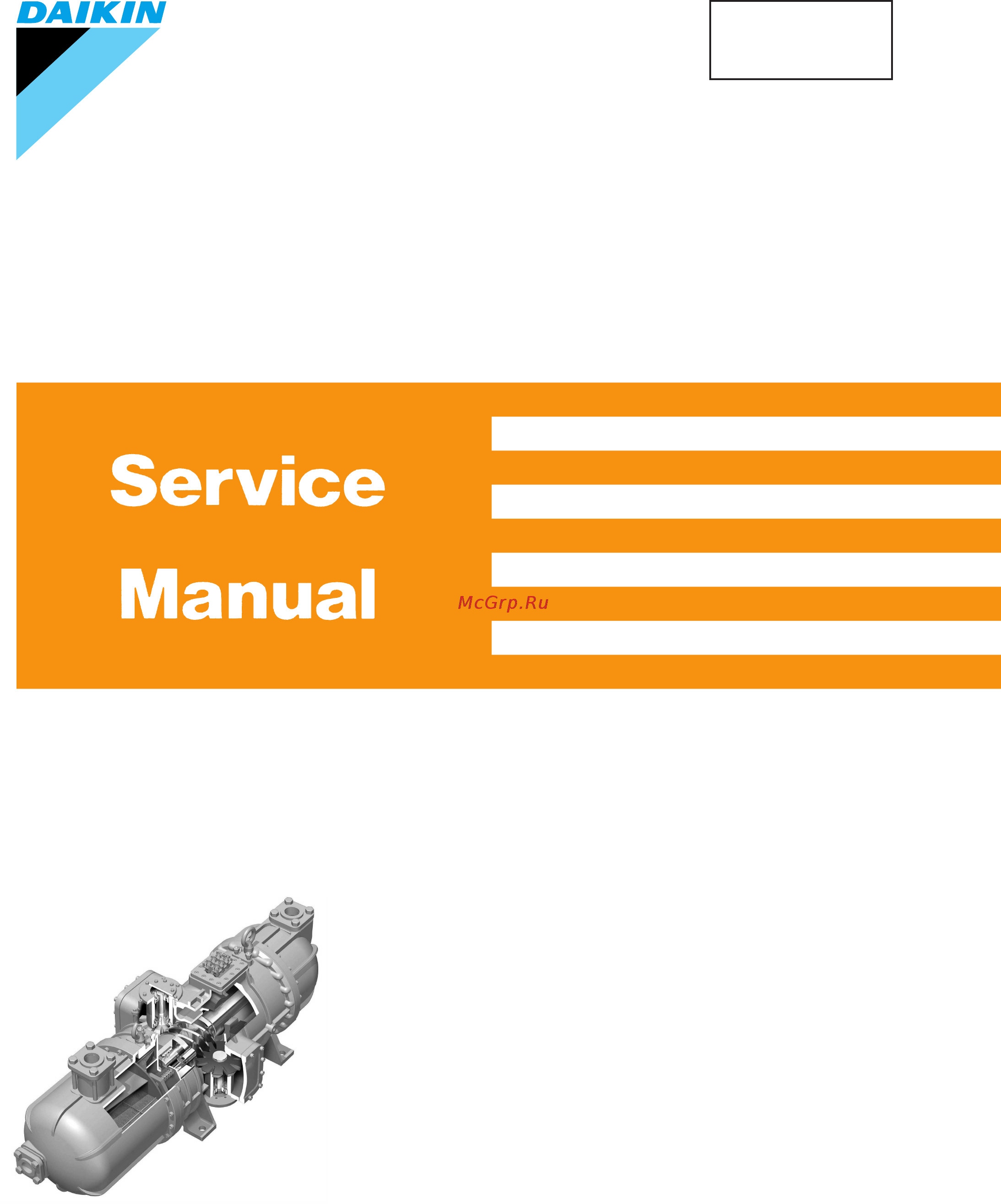
Semi-Hermetic Single Screw
Compressor Version
For Overhaul and Inspection
Si50-402
[Applied Models]
ZH(C)3LSF ZH(C)3LTG ZH(C)3LTGU ZH(C)3LTGV
ZH(C)5MLF ZH(C)3WLG ZH(C)3WLGU ZH(C)3WLGV
ZH(C), (A)5LLF ZH(C), (A)5LMG ZH(C), (A)5LMGU ZH(C), (A)5LMGV
ZH(C), (A)7SLF ZH(C), (A)5WLG ZH(C), (A)5WLGU ZH(C), (A)5WLGV
ZH(C)7LLF ZH(C)7LSG ZHA7MSGU ZHA7MSGV
ZH(C), (A)9SLF ZH(C), (A)7WSG ZH(C)7LSGU ZH(C)7LSGV
ZH(C), (A)9LLF ZH(C), (A)9LSG ZH(C), (A)7WSGU ZH(C), (A)7WSGV
ZH3LMF ZH(C), (A)9WSG ZH(C), (A)9LSGU ZH(C), (A)9LSGV
ZH5SLF ZH(C), (A)9WSGU ZH(C), (A)9WSGV
ZH5LMF
ZHA7MLF
Содержание
- For overhaul and inspection 1
- Semi hermetic single screw compressor version 1
- Si50 402 1
- Airtightness test 5 6 charging oil 6 7 caution in test operation 7 8 required tools 8 2
- Continuous capacity control unit disassembly of control motor 1 4 replacing the bearing 3 2
- Disassembly and inspection 2 2
- Overhaul instructions 1 2
- Periodic inspection instructions 2
- Periodic inspection items and intervals 2
- Replacement of o ring of drive shaft bushing continuous capacity control unit 7 4 final assembly 8 2
- Scope of application 2 overhaul 3 periodic inspection 2
- Semi hermetic single semi hermetic single semi hermetic single semi hermetic single screw compressor screw compressor screw compressor screw compressor version iv version iv version iv version iv 2
- Table of contents 2
- Scope of application 3
- Overhaul 4
- Periodic inspection 5
- Periodic inspection items and intervals 5
- Periodical inspection means to inspect adjust and clean various parts of devices and equipment at the scheduled interval 5
- Table 3 1 shows periodic inspection items and intervals conduct inspections at the earliest indicated inspection intervals 5
- Periodic inspection instructions 6
- 1 perform a pump down operation to reduce pressure inside the compressor 2 release the internal pressure of the compressor loosen the flare nut of the service port with check valve of the compressor same as section 3 2 remove the partition lid then tighten the flare nut to discharge refrigerant from the compressor 3 remove the side caps from both sides of the compressor fig 3 4 since a small amount of oil is still in the compressor place drain pans under the side caps to receive oil before opening the side caps 9
- 4 inspection of the gate rotor visually check the gate rotor surface for scar chipping cracking etc check all gate rotor teeth 9
- Inspecting the gate rotor 9
- This inspection is done to check that no abnormal condition is present due to dust and other foreign particles inside or harsh operating conditions of liquid compression etc 9
- Overhaul instructions 12
- The driving and friction parts in the compressor wear for prolonged over time to prevent accidents caused by worn parts it is necessary to inspect those parts regularly and overhaul the compressor as needed 12
- Disassembly and inspection 13
- 3 disassembling the screw assembly remove the bolts and remove the screw bearing retainer plate remove the main bearing holder from the screw shaft do not lose screw rotor adjusting shims 2 21
- Check that the control motor is in its 100 position if this motor is not in the 100 position it cannot be disassembled the following section shows the checking method 22
- Check the position of the control motor 22
- Continuous capacity control unit disassembly of control motor 22
- Should the control motor not be in its 100 position pass a rated voltage of the control motor through each pin as shown in table below reference it takes approximately two minutes for the motor to move from 0 to 100 the motor stops at 0 or 100 via a micro switch 22
- The position of the control motor can be checked on the opening degree indication plate or according to the position of brass block provided on the side plate of the motor 22
- Removing bearings 24
- Replacing the bearing 24
- Installation of bearings 26
- Replacement of o ring of drive shaft bushing continuous capacity control unit 28
- Final assembly 29
- Airtightness test 36
- Using dry air mixed with refrigerant pressurize to then use a gas detector or soap water to check for leaks apply soap water on the side caps and other cover mounting sections to make sure no air bubbles are formed if air bubbles are formed release the pressure then re tighten the bolts if the leak does not stop check the packing seating surfaces and replace the packing 36
- Charging oil 37
- Part of oil may remain in the refrigerating system therefore charge the same amount of oil removed from the compressor during disassembly when a new gate rotor is installed pour about a half of the total oil capacity to the suction side to prevent excessive heating during initial operation 37
- Caution in test operation 38
- General tools and measuring instruments 39
- Notes 1 indicate metric coarse threads and standard bolts 5t 12 2 tolerances on tightening torque are 15 however the tolerance on tightening torque at terminal block is 5 3 when tightening hexagon socket head cap screws in the compressor apply specifications for class 12 39
- Required tools 39
- The tightening torque of hexagon socket head screw used for control motor is to be 3 n m 15 39
- Special tools for an overhaul be sure to prepare jigs listed in table 8 3 40
- Jig 1 lock nut tightening jig 41
- Bearing outer ring 42
- Jig 2 1 bearing removing jig set 42
- Suction end cover housing section 42
- Jig 2 1 bearing removing jig parts 43
- Bearing outer ring 44
- Cylindrical roller bearing 44
- Holding device 44
- Jig 2 2 bearing removing jig set 44
- Suction end cover housing section 44
- Jig 2 2 bearing removing jig parts 45
- Jig 3 temporary bearing holder mounting plate jig for zh3_ material ss400 46
- Jig 3 temporary bearing holder mounting plate jig for zh5_ material ss400 47
- Jig 3 temporary bearing holder mounting plate jig for zh7_ material ss400 48
- Jig 3 temporary bearing holder mounting plate jig for zh9_ material ss400 49
- Jig 4 1 handle jig set 50
- Jig 4 2 handle jig set 51
- Jig 4 2 handle jig parts 52
- Jig 5 oil filter removing jig for zh3_f 53
- Jig 6 lever for continuous capacity control unit material ss400 54
- Index index index index 56
- Drawings flow charts 57
- Drawings flow charts drawings flow charts drawings flow charts drawings flow charts 57
- Printed in japan 03 2004 ak 58
- The specifications designs and information in this manual are subject to change without notice 58
Похожие устройства
- Daikin ZH7LLF Инструкция по эксплуатации III ver
- Daikin ZH7LLF Инструкция по эксплуатации IV ver
- Daikin ZH9SLF Инструкция по эксплуатации III ver
- Daikin ZH9SLF Инструкция по эксплуатации IV ver
- Daikin ZH9LLF Инструкция по эксплуатации III ver
- Daikin ZH9LLF Инструкция по эксплуатации IV ver
- Daikin ZH3LMF Инструкция по эксплуатации III ver
- Daikin ZH3LMF Инструкция по эксплуатации IV ver
- Daikin ZH5SLF Инструкция по эксплуатации III ver
- Daikin ZH5SLF Инструкция по эксплуатации IV ver
- Daikin ZH5LMF Инструкция по эксплуатации III ver
- Daikin ZH5LMF Инструкция по эксплуатации IV ver
- Daikin ZHC3LSF Инструкция по эксплуатации III ver
- Daikin ZHC3LSF Инструкция по эксплуатации IV ver
- Daikin ZHC5MLF Инструкция по эксплуатации III ver
- Daikin ZHC5MLF Инструкция по эксплуатации IV ver
- Daikin ZHC5LLF Инструкция по эксплуатации IV ver
- Daikin ZHC5LLF Инструкция по эксплуатации III ver
- Daikin ZHC7SLF Инструкция по эксплуатации IV ver
- Daikin ZHC7SLF Инструкция по эксплуатации III ver