
Gigabyte iSolo 3134 Инструкция онлайн
Содержание
- Accessory box 1
- Casing s internal structure 1
- Gigabyte 1
- Step 1 removal of side and front panel 1
- Step 2 installation of power supply 1
- Step 3 installation of motherboard 1
- Step 4 installation of front i o port 1
- Step 6 installation of 5 5 3 external driver bay 1
- Step 7 installation of 3 internal driver bay 1
Похожие устройства
- Gigabyte Setto 1020 Инструкция
- Gigabyte GZ-X7 Инструкция
- Daikin EWYT300B-SSA2-VFDFAN Инструкция по эксплуатации
- Daikin EWYT300B-SSA2-VFDFAN Инструкция по монтажу
- Daikin EWYT300B-SSA2-VFDFAN Технические данные
- Gigabyte GZ-X8 Инструкция
- Daikin EWYT340B-SSA2 Технические данные
- Daikin EWYT340B-SSA2 Инструкция по эксплуатации
- Daikin EWYT340B-SSA2 Инструкция по монтажу
- Daikin EWYT340B-SSA2-VFDFAN Технические данные
- Daikin EWYT340B-SSA2-VFDFAN Инструкция по эксплуатации
- Daikin EWYT340B-SSA2-VFDFAN Инструкция по монтажу
- Daikin EWYT390B-SSA2 Инструкция по эксплуатации
- Daikin EWYT390B-SSA2 Инструкция по монтажу
- Daikin EWYT390B-SSA2 Технические данные
- Daikin EWYT390B-SSA2-VFDFAN Инструкция по эксплуатации
- Daikin EWYT390B-SSA2-VFDFAN Технические данные
- Daikin EWYT390B-SSA2-VFDFAN Инструкция по монтажу
- Daikin EWYT430B-SSA2 Инструкция по эксплуатации
- Daikin EWYT430B-SSA2 Технические данные
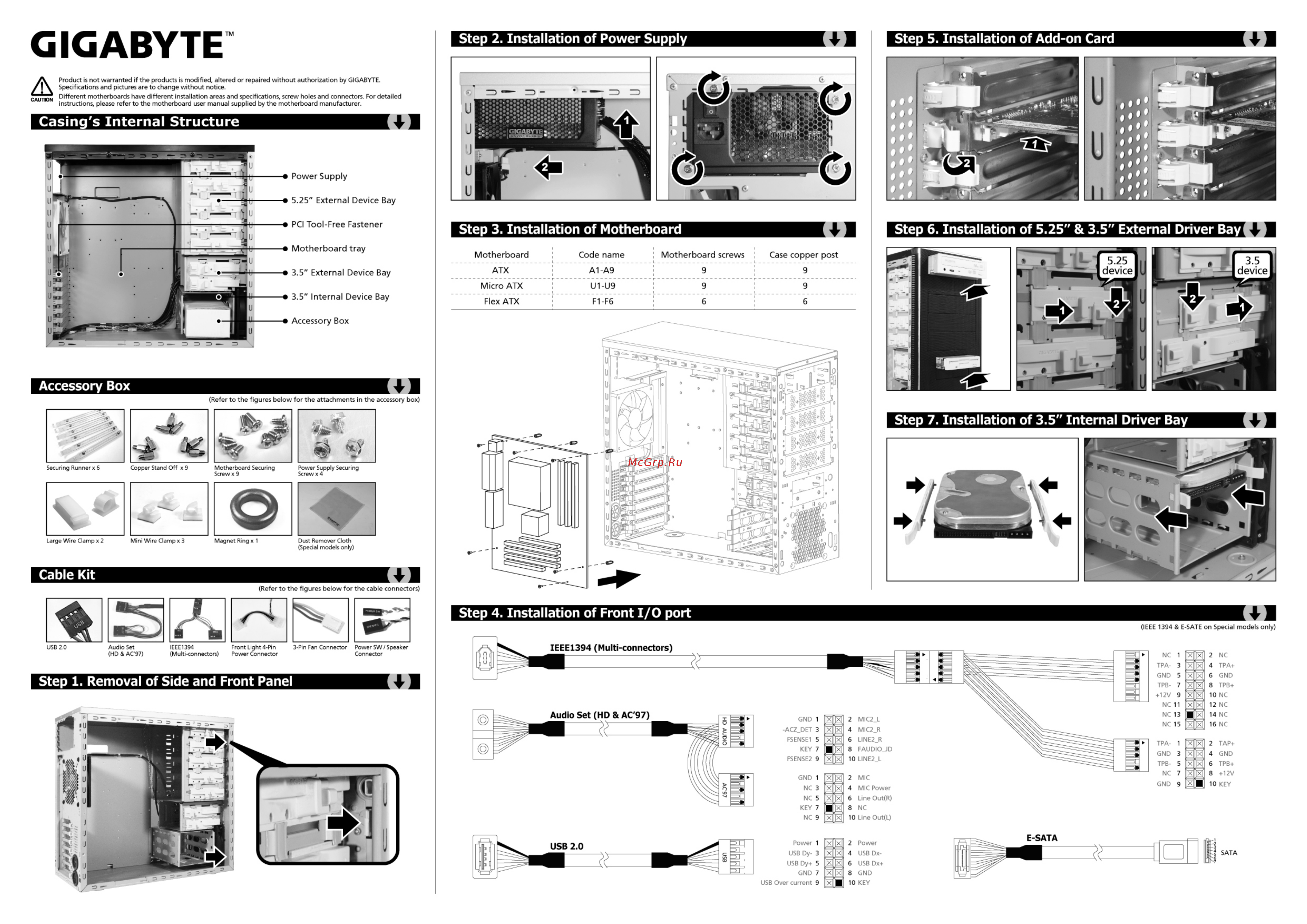
GIGABYTE Step 2 Installation of Power Supply Product is not warranted if the products is modified altered or repaired without authorization by GIGABYTE Specifications and pictures are to change without notice CAUTION Different motherboards have different installation areas and specifications screw holes and connectors For detailed instructions please refer to the motherboard user manual supplied by the motherboard manufacturer Casing s Internal Structure Power Supply 5 25 External Device Bay PCI Tool Free Fastener Motherboard tray 3 5 External Device Bay 3 5 Internal Device Bay Step 3 Installation of Motherboard Motherboard Code name Step 6 Installation of 5 25 3 5 External Driver Bay Motherboard screws Case copper post ATX A1 A9 9 9 Micro ATX U1 U9 9 9 Flex ATX F1 F6 6 6 Accessory Box Accessory Box Refer to the figures below for the attachments in the accessory box Step 7 Installation of 3 5 Internal Driver Bay Securing Runner x 6 Copper Stand Off x 9 Motherboard Securing Power Supply Securing Screw x 9 Screw x 4 Step 4 Installation of Front I O port IEEE 1394 E SATE on Special models only Step 1 Removal of Side and Front Panel