
MUST PV11-2400 Plus Инструкция онлайн
Solar System
High Frequency Solar Inverter
-03- -04-
PV1100 Plus Series
High Frequency Solar Inverter
Power Rate(w)
backup time(H)
@1*100Ah
backup time(H)
@2*100Ah
backup time(H)
@4*100Ah
backup time(H)
@4*200Ah
1000
1440
0.94 1.88
1.4
3.76 7.52
720 1.3 2.6 5.2 10.4
2.8 5.6
Approximate Back-up Time Table
Feature:
Introduction:
Back Panel
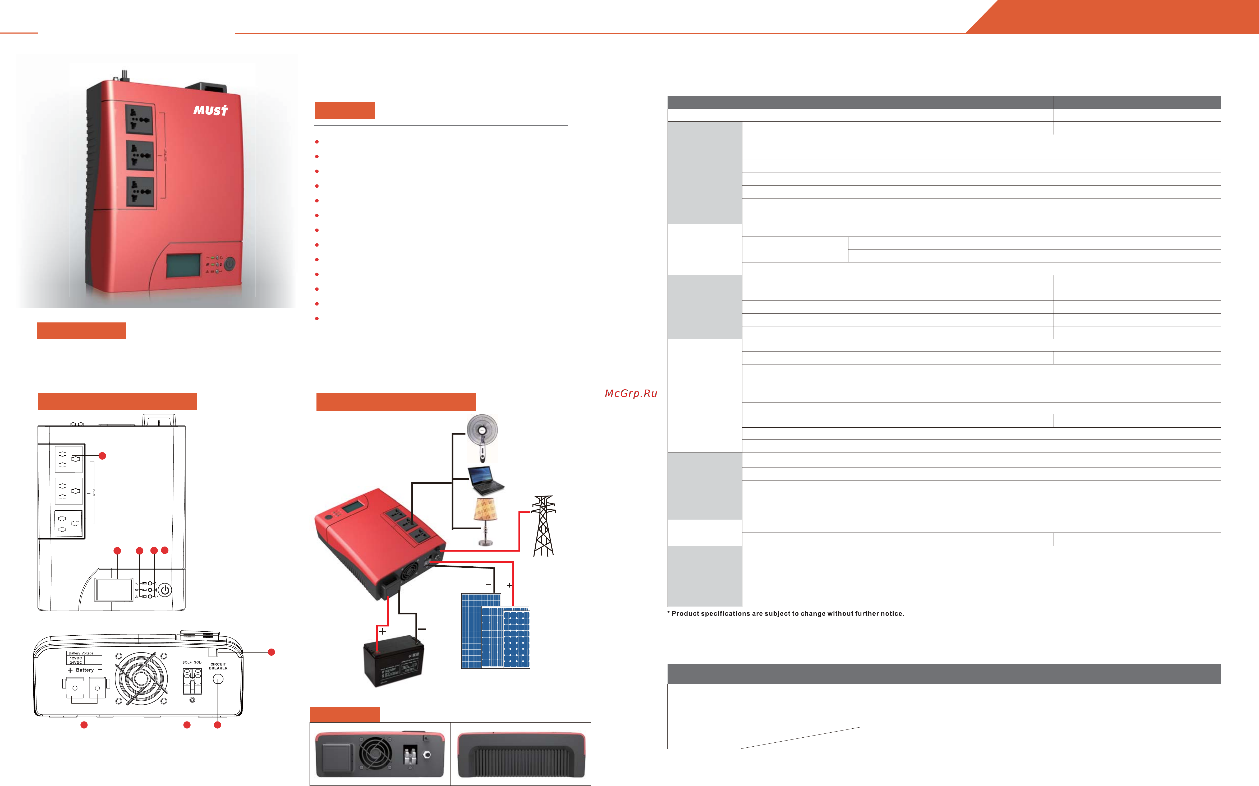
Solar System Connection
Simulated sine wave inverter
Built-in 50Amp charge controller
10A or 20A standard charging current from utility
AC/solar priority for output via MFD
AC/solar priority for charging via MFD
Smart user friendly interface
3 steps charging algorithm
MFD (multi-function display)
Overload & short-circuit protection
Battery reverse polarity protection
Deep discharge protection
Auto restart while AC/solar is recovering
Adjustable solar and utility charging current
Narrow
Wide
2.8
2400VA/1440W
Rated Power
Output Voltage Regulation
+10/-18%
MODEL
PV11-2400 Plus
Default Battery System Voltage
PV11-1800 Plus
1800VA/1000W
12VDC
PV11-1400 Plus
1400VA/720W
12VDC 24VDC
Modifided Sine-wave
Voltage
230VAC
Output Frequency
50Hz/60Hz +/-1 Hz
Nominal Output Voltage RMS
Inverter Efficiency(Peak)
>80%
Line Mode Efficiency
>98%
INVERTER
OUTPUT
230V
Typical Transfer Time
Typical 15~20ms 40ms max
Waveform
Selectable Voltage Range
170~280VAC
90~280VAC
AC
INPUT
Frequency Range 40Hz-70Hz (Auto sensing)
BATTERY
Nominal Input Voltage
12VDC 24VDC
Minimum Start Voltage
10.5VDC 21.0VDC
Low Battery Alarm
10.4VDC (min) 20.8VDC (min)
Low Battery Cutoff
9.9~12VDC (Can be set) 19.8~24VDC (Can be set)
High Voltage Cutoff
15.0VDC (max) 30.0VDC (max)
MECHANICAL
SPECIFICATIONS
Dimensions (W*H*D)
290*232*83mm
Net Weight (kg)
3.0
OTHER
Operation Temperature Range
0°C to 50°C
Audible Noise
50dB MAX
Display
LED+LCD
Loading(20GP/40GP/40HQ) 1700pcs / 3400pcs / 4100pcs
AC Charger Voltage 14.5(max)
10A / 20A (Can be set)
29(max)
AC Charging Current
Maximum Charge Current
BYPASS
&
PROTECTION
Nominal Input Frequency 40Hz - 70Hz
Overload Protection (SMPS Load)
FUSE
Output Short Circuit Protection
FUSE
Bypass Fuse Rating
10A
10-50A (Can be set)
10Amp
Max Bypass Current
SOLAR
CHARGER
&
AC CHARGER
Maximum PV Array Open Circuit Voltage
Maximum Efficiency
50A (max)
55VDC
>95%
<2W
450W/750W
Standby Power Consumption
900W/1500W
Maximum PV Charge Current
Maximum PV Array Power
PWM Range @ Operating Voltage
16~55VDC
1. DC Input Wires
2. Input fuse
3. PV input,note that the polarity is not reversed.
4. AC input
1. Status indicators
2. LCD display
3. POWER switch
4. Output Receptacle(s)
5. Settings button
Figure 1 Top Panel
Figure 2 Back Panel
LCD Display Information
External
Battery pack
PV panel
2 1
3
Utility
Specification
4
5
It is a cost effective, intelligent solar inverter which accept Solar & Utility input at the same time. The comprehensive LCD display
offers user-configurable and easy-accessible button adjustment such as battery charging current, AC/solar charger priority and
DC priority.When battery voltage low,it will automatically switch to AC grid to supply continuously power to the loads.
1
2
4
3
Содержание
Похожие устройства
- MEAN WELL SP-240-30 Инструкция по эксплуатации
- MEAN WELL SP-240-30 Инструкция язык EN
- MEAN WELL SP-240-30 Data sheet
- MEAN WELL SP-240-30 Документация
- MEAN WELL SP-240-48 Инструкция по эксплуатации
- MEAN WELL SP-240-48 Инструкция язык EN
- MEAN WELL SP-240-48 Data sheet
- MEAN WELL SP-240-48 Документация
- MUST PV15-500 Инструкция
- MUST PV15-800 Инструкция
- MUST PV18-1K PK Инструкция
- MUST PV18-2K PK Инструкция
- MUST PV18-3K PK Инструкция
- MUST PV18-4K PK Инструкция
- MEAN WELL SP-320-3.3 Инструкция по эксплуатации
- MEAN WELL SP-320-3.3 Инструкция язык EN
- MEAN WELL SP-320-3.3 Data sheet
- MEAN WELL SP-320-3.3 Документация
- MUST PV18-5K PK Инструкция
- MEAN WELL SP-320-5 Инструкция по эксплуатации