
TRACO POWER TPC 120–112 Инструкция по установке онлайн
Safety Instructions and Warnings
Do not open the device!
Before any installation, or maintenance, ensure that the main switch is
switched off and prevented from being switched on again.
The device can be installed and put into service by qualified personnel only.
Never work on the device if power is applied.
Risk of electric arcs and electrical shock, which can cause death, severe
personal injury or substantial property damage.
The unit must be connected to the mains supply in compliance with national
regulations (e.g. VDE0100 and EN50178). All wire strands must be fastened
in the terminal blocks. (Potential danger of contact with the case)
All input and output wires must be properly rated for the power supply and
must be connected with the correct polarity. Fig.3
The Power Supply wiring must be sufficiently fused.
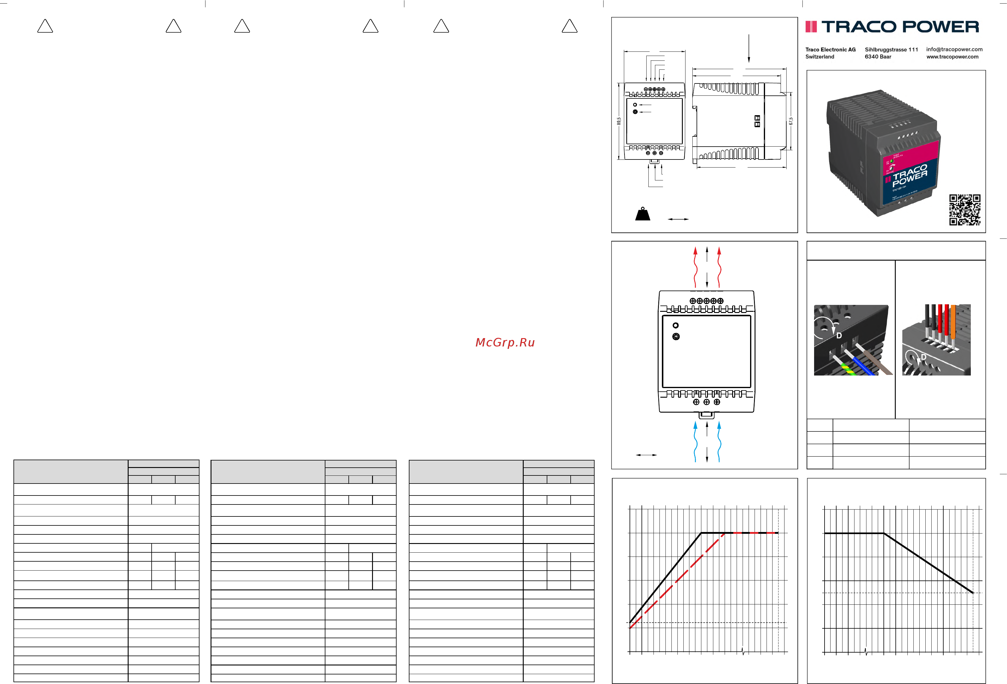
Sufficient cooling must be ensured. Fig.2
Do not introduce any objects into the device.
The output voltage adjustment potentiometer may only be actuated using
an insulated screwdriver.
Keep away from fire and water.
The internal fuse is not accessible. If this internal fuse has blown, the power
supply has an internal defect and, for safety reasons, must be shipped to the
local distributor.
This device is designed for use in a clean, dry environment.
The device shall be mounted in an enclosure in the end application. The
power supply is not accessible in operation.
Installation Instructions
The device can be mounted onto 35mm DIN rails, compliant with the
specifications of DIN EN 50022. Observe the requirements for ventilation space
above and below the device. Fig.2.
The standard mounting orientation is with input terminals (I/P) at the bottom.
Recycling
The device contains elements that are suitable for recycling, and components
that need special disposal. You are therefore requested to make sure that the
device will be recycled at the end of its service life.
Identification of Features (Fig.1)
1. Input Terminal
2. Input Terminal
3. Input Terminal
4.Output Connection Terminal
5.Output Connection Terminal
6. Output Connection Terminal
7..Output Connection Terminal
8. DC OK : PNP open collector
Trigger: 80 - 95% (48V models: max. 5mA; other models: max.10mA)
9. DC ON LED
10. Output Voltage adjustment potentiometer
11. Remote On/Off 10mA current source
! ! !! ! !
EN DE FR
Consignes de sécurité et avertissements
Ne pas ouvrir l'appareil !
Avant toute installation ou action d'entretien, s'assurer que l'interrupteur
principal soit éteint et sécurisé contre toute remise en marche.
L'appareil peut être installé et mis en service uniquement par du personnel
qualifié.
Ne jamais travailler sur l'appareil, quand il est mis sous tension.
Risque d'arcs et de chocs électriques, qui peuvent provoquer des blessures
corporelles graves, la mort ou des dégâts matériels importants.
L'appareil doit être branché à l'alimentation dans le respect des
réglementations nationales (par ex. VDE0100 et EN50178). Tout brin de fil
doit être fixé dans les borniers (Risque potentiel de contact avec le casier).
Tous les fils d'entrée et de sortie doivent être correctement étalonnés pour
le bloc d'alimentation et être branchés à la bonne polarité. Fig.3
Le câblage d'alimentation doit être protégé par des fusibles de calibre
suffisant.
Assurer un refroidissement suffisant. Fig.2
Ne pas introduire d'objets dans l'appareil.
Le potentiomètre de réglage de la tension de sortie peut uniquement être
actionné à l'aide d'un tournevis isolé.
Tenir à l'écart du feu et de l'eau.
Le fusible interne n'est pas accessible. Si ce fusible interne est grillé, le bloc
d'alimentation présente un défaut interne et, pour des raisons de sécurité, il
doit être expédié au distributeur local.
L'appareil est conçu pour être utilisé dans un environnement propre et sec.
L'appareil doit être monté à l'intérieur d'une enceinte dans l'application
finale. Pendant le fonctionnement, le bloc d'alimentation n'est pas
accessible.
Instructions d'installation
L'appareil peut être monté sur des rails DIN de 35 mm, conformes aux
spécifications de la norme DIN EN 50022.Respecter les exigences en matière
d'espace de ventilation au-dessus et en dessous de l’appareil. Fig.2
L'orientation standard du support prévoit que les bornes d'entrée (I/P) se
trouvent en bas.
Recyclage
L'appareil contient des éléments appropriés au recyclage et des composants
nécessitant une mise au rebut particulière. L'utilisateur est donc prié de s'assurer
que l’appareil sera recyclé à la fin de sa durée de vie.
Identification des caractéristiques Fig.1
1. Borne de branchement d'entrée
2. Borne de branchement d'entrée
3. Borne de branchement d'entrée
4. Borne de branchement de sortie
5. Borne de branchement de sortie
6. Borne de branchement de sortie
7. Borne de branchement de sortie
8 .DC OK: collecteur ouvert PNP
Déclenchement: 80-95 % (modèles 48 V : 5 mA maxi, autres: 10 mA maxi)
9. CC SUR DEL
10. Potentiomètre de réglage de la tension de sortie
11. Marche/arrêt à distance (source de courant 10 mA)
Sicherheitsinstruktionen und Warnungen
Das Gerät nicht öffnen!
Vor Installations- oder Wartungsarbeiten muss sichergestellt sein, dass der
Hauptschalter der Applikation ausgeschaltet ist und ein Einschalten
verhindert wird.
Das Gerät darf und nur von qualifiziertem Personal installiert und in Betrieb
genommen werden.
Nie am Gerät arbeiten, wenn Spannung angelegt ist.
Es besteht das Risiko eines elektrischen Schlages und Entstehung von
Lichtbögen, welche lebensgefährliche Körperverletzungen oder
Sachschäden verursachen können.
Der Anschluss des Geräts an das Versorgungsnetz muss den nationalen
Vorschriften entsprechen (z.B. VDE0100 und EN50178). Alle Drähte
müssen an den Anschlussklemmen befestigt sein (Potentielles Risiko eines
Kontakts mit dem Gehäuse).
Alle Verdrahtungen am Eingang und Ausgang müssen entsprechend dem
Netzteil ausgelegt und mit der richtigen Polarität verbunden sein. Fig.3
Die Stromversorgung muss ausreichend abgesichert sein.
Für ausreichende Kühlung muss gesorgt sein. Fig.2
Es dürfen keine Gegenstände in das Gerät eingeführt werden.
Die Verstellung des Ausgangspannungspotentiometers darf nur mit einem
isolierten Schraubendreher vorgenommen werden.
Von Feuer und Wasser fernhalten.
Die interne Sicherung ist nicht zugänglich. Falls diese auslöst hat die
Stromversorgung einen internen Defekt und muss aus Sicherheitsgründen
zum lokalen Distributor zurückgeschickt werden.
Das Gerät ist für den Gebrauch in sauberer und trockener Umgebung
bestimmt.
Das Gerät muss in der Endapplikation in einem Gehäuse montiert sein. Die
Stromversorgung darf im Betrieb nicht zugänglich sein.
Einbauanweisungen
Das Gerät kann an 35 mm DIN-Schienen montiert werden, in Übereinstimmung
mit der Spezifikation DIN EN 50022. Dabei sind die Anforderungen an die
Ventilationsabstände über und unter dem Gerät einzuhalten. Fig.2
Die Standardmontageausrichtung ist mit den Eingangsanschlüssen (I/P) auf der
unteren Seite.
Entsorgung
Das Gerät enthält Bestandteile, welche zum Recycling geeignent sind und
Komponenten, welche fachgerecht entsorgt werden müssen. Stellen Sie daher
sicher, dass das Gerät nach Gebrauch korrekt entsorgt wird.
Funktionsbeschreibung( Fig.1)
1. Eingangsanschlussklemme
2. Eingangsanschlussklemme
3. Eingangsanschlussklemme
4. Ausgangsanschlussklemme
5. Ausgangsanschlussklemme
6. Ausgangsanschlussklemme
7. Ausgangsanschlussklemme
8. DC OK: PNP offener Kollektor
Auslöser: 80-95% (48 V Modelle: max. 5m A, weitere: max 10 mA)
9. DC Betriebsanzeige LED
10. Ausgangspannungspotentiometer
11. Fernschaltung An/Aus (10 mA Stromquelle)
L
L
L
N
N
N
PE
PE
PE
++
+
++
+
-
-
-
--
-
3
1
2
6
5
4
7
8
109,5
103,1
104,5
71,5
9
10
Fig.1
TPC 120
Industrial Power Supply
www.tracopower.com/overview/tpc
0,44kg
kg
mm
O/P
I/P
Fig.3
Fig.5
P - T (O/P) (amb)
0
-25 -20 5550 706560
20
40
60
80
100
T (amb) [°C]
P/Pmax
[%]
Fig.2
Fig.4
50
85
90
90
100
95
110
100100
120
105
130
264
375
260
365
60
70
80
90
100
V (I/P)
[VAC]
[VDC]
P/Pmax
[%]
P - V (O/P) (I/P)
50
50
mm
11
C
A
B
D
0.7 - 2.5
2.5
19 - 14
14
7
0.5
[mm²]
[mm²]
[mm]
[AWG]
[AWG]
[Nm]
/
/
/
/
B
C
C
A
112 124 148
Nominal Input Voltage
Nominal Input Current 2.0 - 1.1 A 2.6 - 1.4 A 2.4-1.3 A
Operational Input Voltage Range
Input Voltage Frequency Range
Inrush Current (115/230VAC)
Circuit Breaker Rating / Characteristic
Max. Output Power 96 W
Output Voltage 12 V 24 V 48 V
Max. Output Current 8.0 A 5.0 A 2.5 A
Output Voltage Adjustment Range
12 -
15 V
24 -
28.8 V
48-
56 V
Typical Efficiency (230 VAC) 85% 87% 90%
Operating Temperature Range
Output Power Derating - Temperature
Output Power Derating - Input Voltage
Protection Class
Degree of Protection
Leakage Current (max.)
Network Configuration
Humidity
Storage Temperature
Maximum Altitude
IP20
Class I
120 W
SPECIFICATIONS
20/40 A
6 A / C
-25°C to +70°C
2.5%/K above 50°C
2.5%/V below 100 VAC
1.0%/V below 130 VDC
1.0 mA
TN-S, TN-C, TT, IT
95%, no condensation
-25°C to +85°C
2000 m
Order Code
TPC 120-
100 - 240 VAC
130 - 300 VDC
85 - 264 VAC
90 - 375 VDC
47 - 63 Hz
112 124 148
Nominale Eingangsspannung
Nominaler Eingangsstrom 2.0 - 1.1 A 2.6 - 1.4 A 2.4-1.3 A
Eingangsbetriebsspannungbereich
Eingangsspannungsfrequenzbereich
Einschaltstrom (115/230 VAC)
Sicherungsnennwert / Charakteristik
Max. Ausgangsleistung 96 W
Ausgangsspannung 12 V 24 V 48 V
Max. Ausgangsstrom 8.0 A 5.0 A 2.5 A
Ausgangsspannungseinstellbereich
12 -
15 V
24 -
28.8 V
48-
56 V
Typischer Wirkungsgrad (230 VAC) 85% 87% 90%
Betriebstemperaturbereich
Ausgangsleistungsminderung – Temperatur
Ausgangsleistungsminderung - Eingangsspanung
Schutzklasse
Schutzart
Kriechstrom (max.)
Netzstruktur
Luftfeuchtigkeit
Lagertemperatur
Maximale Höhe
TN-S, TN-C, TT, IT
95%, keine Betauung
2.5%/K oberhalbe 50°C
2.5%/V unterhalb 100 VAC
1.0%/V unterhalb 130 VDC
Klasse I
SPEZIFIKATIONEN
Bauteilbezeichnung
TPC 120-
100 - 240 VAC
130 - 300 VDC
-25°C bis +85°C
2000 m
85 - 264 VAC
90 - 375 VDC
47 - 63 Hz
20/40 A
6 A / C
120 W
-25°C bis +70°C
IP20
1.0 mA
112 124 148
Tension nominale d'entrée
Courant nominal d'entrée 2.0 - 1.1 A 2.6 - 1.4 A 2.4-1.3 A
Plage de tension d'entrée opérationnelle
Plage de fréquence de tension d'entrée
Courant d'appel (115/230 VCA)
Valeur nominale / caractéristiques du disjoncteur
Puissance de sortie maxi 96 W
Tension de sortie 12 V 24 V 48 V
Courant de sortie maxi 8.0 A 5.0 A 2.5 A
Plage de réglage de la tension de sortie
12 -
15 V
24 -
28.8 V
48-
56 V
Rendement typique (230 VCA) 85% 87% 90%
Température de fonctionnement
Réduction de la puissance de sortie - Température
Réduction de la puissance de sortie - Tension d'entrée
Classe de protection
Degré de Protection
Courant de fuite (maxi)
Configuration du réseau
Humidité
Température de stockage
Altitude maximale
TN-S, TN-C, TT, IT
95%, sans condensation
-25°C à +85°C
-25°C à +70°C
2.5%/K en amont de 50°C
2.5%/V au dessous de 100 VCA
1.0%/V au dessous de 130 VCC
Classe I
IP20
1.0 mA
2000 m
SPÉCIFICATIONS
Code de commande
TPC 120-
100 - 240 VCA
130 - 300 VCC
85 - 264 VCA
90 - 375 VCC
47 - 63 Hz
20/40 A
6 A / C
120 W
© Copyright 2019 Traco Power Solutions Ltd.Specifications can be changed without notice
Rev. Oct 10,2019
Содержание
- 100 120 1
- 124 148 1
- 25 20 55 50 70 65 60 1
- Bauteilbezeichnung 1
- Code de commande 1
- Consignes de sécurité et avertissements 1
- Copyright 2019 traco power solutions ltd 1
- Industrial power supply 1
- O p amb 1
- O p i p 1
- Order code tpc 120 1
- Pe pe pe 1
- Safety instructions and warnings 1
- Sicherheitsinstruktionen und warnungen 1
- Specifications 1
- Specifications can be changed without notice rev oct 10 2019 1
- Spezifikationen 1
- Spécifications 1
- Tpc 120 1
- Www tracopower com overview tpc 0 44kg 1
- 100 120 2
- 124 148 2
- 25 20 55 50 70 65 60 2
- Codice per l ordinazione 2
- Copyright 2019 traco power solutions ltd 2
- Código de pedido 2
- Especificaciones 2
- Industrial power supply 2
- O p amb 2
- O p i p 2
- Pe pe pe 2
- Specifications can be changed without notice rev oct 10 2019 2
- Specifiche 2
- Tpc 120 2
- Www tracopower com overview tpc 0 44kg 2
- Безопасности и предупреждения 2
- Все входные и выходные провода должны быть надлежащим образом рассчитаны на работу с блоком питания и должны быть подключены с соблюдением правильной полярности fig 2
- Выходная соединительная клемма 2
- Данное устройство предназначено для использования в чистом сухом помещении 2
- Действия с потенциометром регулировки выходного напряжения разрешается выполнять только с помощью изолированной отвертки 2
- Держите прибор вдали от огня и воды 2
- Доступ к внутреннему плавкому предохранителю отсутствует если этот внутренний плавкий предохранитель перегорел это означает что у блока питания имеется внутренний дефект поэтому он по соображениям безопасности должен быть отправлен местному дистрибьютору 2
- Инструкции по технике 2
- Инструкции по установке данное устройство может быть установлено на рейки din 35 мм отвечающие спецификациям din en 50022 соблюдайте требования к вентиляционным зазорам сверху и снизу устройство fig 2 стандартная монтажная ориентация предусматривает расположение выходных клемм i p внизу 2
- Код заказа 2
- Не открывайте прибор 2
- Не помещайте никакие предметы внутрь устройства 2
- Никогда не работайте с устройством находящимся под напряжением 2
- Описание компонентов fig 1 входная соединительная клемма 2 входная соединительная клемма 3 входная соединительная клемма 4 выходная соединительная клемма 5 выходная соединительная клемма 2
- Перед установкой или проведением технического обслуживания убедитесь что главный выключатель выключен и защищен от включения 2
- Пост ток в норме pnp транзистор с открытым коллектором 2
- Прибор должен подключаться к электросети в соответствии с требованиями национальных норм например vde0100 и en50178 все жилы проводов должны быть закреплены в клеммных колодках риск контакта с корпусом 2
- Следует обеспечить надлежащее охлаждение прибора fig 2
- Срабатывание 80 95 модели на 48 в макс 5 ма прочие макс 10 ма 9 светодиодный индикатор включения 10 потенциометр регулировки выходного напряжения 11 дистанционное вкл выкл источник тока 10 ма 2
- Существует риск создания электрических дуг и поражения электрическим током что может привести к гибели людей тяжким телесным повреждениям или существенному повреждению имущества 2
- Технические 2
- Установку и ввод устройства в эксплуатацию должен осуществлять только квалифицированный персонал 2
- Устройство должно быть помещено в кожух установки целевого назначения доступ к блоку питания во время работы отсутствует 2
- Утилизация блок содержит элементы пригодные для повторной переработки и компоненты которые требуют особого способа утилизации поэтому вы должны обеспечить переработку по окончании его срока службы устройство 2
- Характеристики 2
- Электропроводка блока питания должна быть надежно защищена плавкими предохранителями 2
Похожие устройства
- TRACO POWER TPC 120–112 Документация
- TRACO POWER TPC 120–124 Инструкция по эксплуатации
- TRACO POWER TPC 120–124 Datasheet
- TRACO POWER TPC 120–124 Инструкция по установке
- TRACO POWER TPC 120–124 Документация
- TRACO POWER TPC 120–148 Инструкция по эксплуатации
- TRACO POWER TPC 120–148 Datasheet
- TRACO POWER TPC 120–148 Инструкция по установке
- TRACO POWER TPC 120–148 Документация
- Daikin RXY26MTL Инструкция по эксплуатации
- Daikin RXY26MTL Руководство по эксплуатации
- TRACO POWER TSP–BCM12 Инструкция по эксплуатации
- TRACO POWER TSP–BCM12 Инструкция по установке
- TRACO POWER TSP–BCM12 Datasheet
- TRACO POWER TSP–BCM12 Документация
- TRACO POWER TSP–BCM24 Инструкция по эксплуатации
- TRACO POWER TSP–BCM24 Инструкция по установке
- TRACO POWER TSP–BCM24 Datasheet
- TRACO POWER TSP–BCM24 Документация
- TRACO POWER TSP–BCM48 Инструкция по эксплуатации