
Planet ISW-501T Инструкция по эксплуатации онлайн
- 1 -
- 2 -
- 3 -
- 4 -
- 5 -
- 6 -
- 7 -
- 8 -
1. Package Content
Thank you for purchasing PLANET 5/8-Port 10/100Mbps
unmanaged Industrial Fast Ethernet Switch, ISW-501T
/ ISW-801T. Terms of “Industrial Fast Ethernet Switch” in
following section of this User’s Manual means the ISW-501T
/ ISW-801T.
Upon open the box of the Industrial Fast Ethernet Switch
and carefully unpack it. The box should contain the
following items:
● TheIndustrialFastEthernetSwitchx1
● User’sManualx1
● DINRailKitx1
● WallMountKitx1
If any of these are missing or damaged, please contact your
dealer immediately, if possible, retain the carton including
the original packing material, and use them against to
repack the product in case there is a need to return it to us
for repair.
3. Product Specication
Model
ISW-501T ISW-801T
Hardware Specication
10/100Base-TX
Ports
5 8
Dimensions
(W x D x H)
135mm x 87mm x 32mm
Weight
438g 454g
Power Requirement
12~48VDC,Redundantpowerwith
polarity reverse protection function
Power Consumption
/ Dissipation
11 Watts / 37BTU
11.6 Watts /
39BTU
Installation
DINrailkitandwallmountear
Switch Specication
Switch Processing
Scheme
Store-and-Forward
Address Table
2Kentries
Flow Control
Back pressure for half duplex, IEEE
802.3x Pause Frame for full duplex
Switch fabric
1Gbps 1.6Gbps
Throughput
(packet per second)
0.74Mpps 1.19Mpps
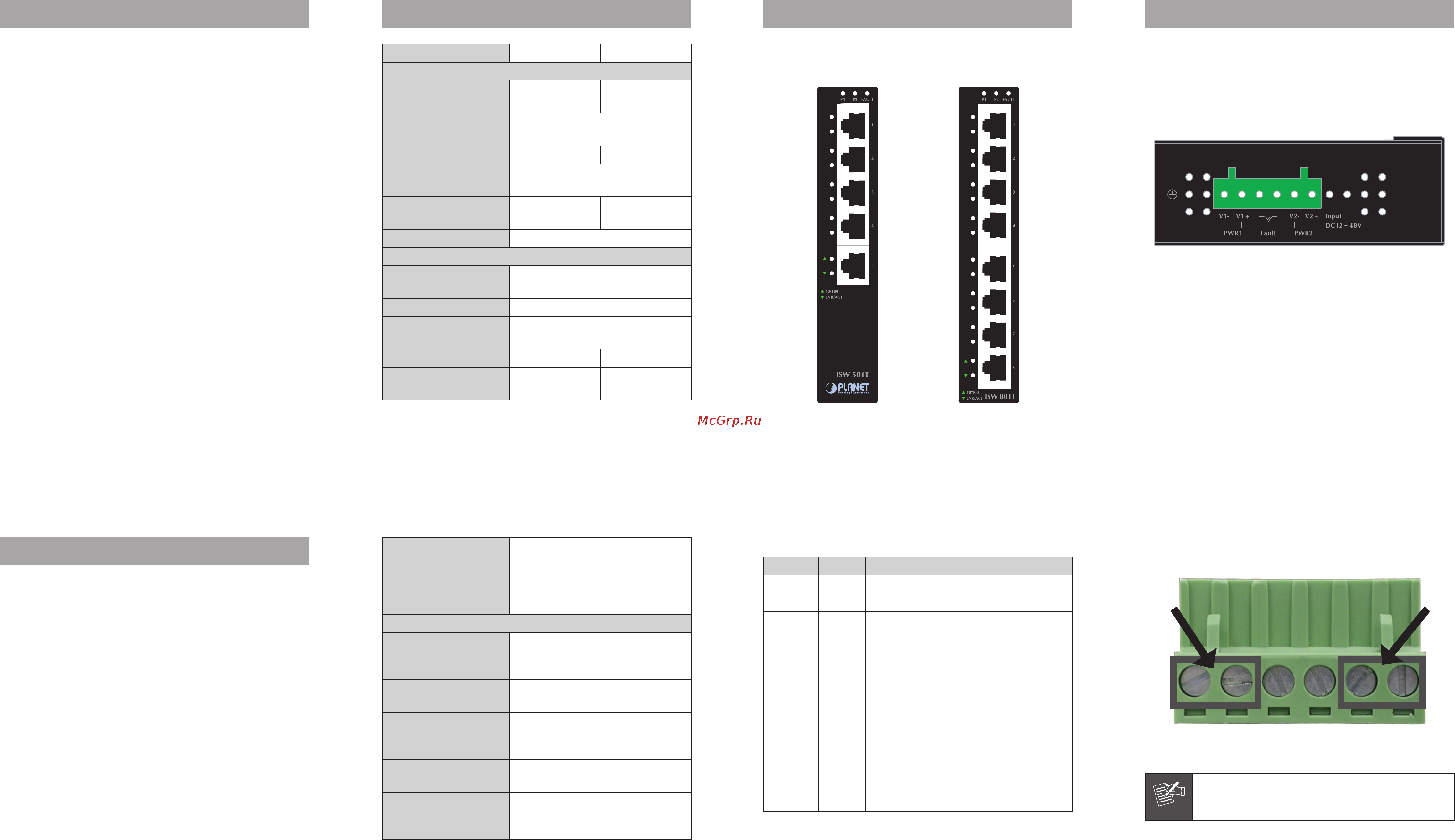
5. Switch Upper Panel
The upper panel of the Industrial Fast Ethernet Switch
consist one terminal block connector within two DC power
inputs.
Figure 3 shows upper panel of Industrial Fast Ethernet
Switch.
Figure 3: Industrial Fast Ethernet Switch Upper Panel
Wiring the Power Inputs
The 6-contact terminal block connector on the top panel
of Industrial Fast Ethernet Switch is used for two DC
redundant powers input. Please follow the steps below to
insert the power wire.
4. Switch Front Panel
Figure 1 & 2 shows a front panel of Industrial Fast Ethernet
Switch.
Figure 1: ISW-501T Front Panel Figure 2: ISW-801T Front Panel
2. Product Features
Physical Port
- 5/8-Port10/100MbpsRJ-45withautoMDI/MDI-Xfunction
Layer 2 Features
- ComplieswithIEEE802.310Base-T,IEEE802.3u100Base-
TX,Ethernetstandard
- Supports Auto-negotiation and 10/100Mbps half / full
duplex mode
- High performance Store and Forward architecture
- Preventspacketlosswithback pressure(Half-Duplex) and
IEEE802.3xPAUSEframeowcontrol(Full-Duplex)
- Backplane (Switching Fabric): ISW-501T: 1Gbps, ISW-
801T: 1.6Gbps
- Integrated address look-up engine, support 2K absolute
MACaddresses
- Automatic address learning and address aging
Industrial Case / Installation
- IP-30 Metal case / Protection
- DINRailandWallMountDesign
- 12 to 48V DC, redundant power with polarity reverse
protect function and connective removable terminal block
for master and slave power
- SupportsEFTprotection6000VDCforpowerline
- Supports6000VDCEthernetESDprotection
- -40to75DegreeCoperationtemperature
- Free fall, shock, vibration industrial stability
Network cables
10/100Base-TX:
Cat.3,4,5,5e,6UTPcable
(100meters,max.)
EIA/TIA-568 100-ohm STP
(100meters,max.)
Standards Conformance
Standards
Compliance
IEEE 802.3 Ethernet
IEEE 802.3u Fast Ethernet
IEEE802.3xFull-duplexowcontrol
Temperature
Operating:-40~75DegreeC
Storage:-40~75DegreeC
Humidity Operating
Operating: 5% to 90%,
Storage: 5% to 90%
(Non-condensing)
Regulation
Compliance
FCCPart15ClassA,CE
Stability testing
IEC60068-2-32(Freefall)
IEC60068-2-27(Shock)
IEC60068-2-6(Vibration)
LED Indicators
LED Color Function
P1 Green Lit: indicate the power 1 has power.
P2 Green Lit: indicate the power 2 has power.
FAULT Green
Lit: indicate the either power 1 or
power 2 has no power.
10/100 Green
Lit: indicate the Switch is successfully
connecting to the network at
100Mbps.
Off: indicate the Switch is successfully
connecting to the network at
10Mbps.
LNK/ACT Green
Lit: indicate the link through that port
is successfully established.
Blink: indicate that the Switch is
actively sending or receiving
data over that port.
Tighten the wire-clamp screws for preventing the wires from
loosing.
1 2 3 4 5 6
Power 1 Fault Power 2
- + - +
Note
The wire gauge for the terminal block should be
in the range between 12 ~ 24 AWG.
Wiring the Fault Alarm Contact
The fault alarm contacts are in the middle of the terminal
block connector as the picture shows below. Inserting
the wires, the Industrial Fast Ethernet Switch will detect
the fault status of the power failure, or port link failure
(available for managed model) and then forms an open
circuit. The following illustration shows an application
example for wiring the fault alarm contacts.
Содержание
- 100base tx ports 1
- Address table 1
- Compliance 1
- Dimensions w x d x h 1
- Flow control 1
- Hardware specification 1
- Humidity operating 1
- Industrial case installation 1
- Installation 1
- Layer 2 features 1
- Led color function 1
- Led indicators 1
- Network cables 1
- Package content 1
- Physical port 1
- Power consumption dissipation 1
- Power requirement 1
- Product features 1
- Product specification 1
- Regulation compliance 1
- Scheme 1
- Stability testing 1
- Standards 1
- Standards conformance 1
- Switch fabric 1
- Switch front panel 1
- Switch processing 1
- Switch specification 1
- Switch upper panel 1
- Temperature 1
- Throughput packet per second 1
- Weight 1
- Wiring the fault alarm contact 1
- Wiring the power inputs 1
- 12 13 14 2
- Customer support 2
- Din rail mounting 2
- Mounting installation 2
- Wall mount plate mounting 2
Похожие устройства
- Elna EXCELLENCE 740 Инструкция по эксплуатации
- Planet ISW-511S15 Инструкция по эксплуатации
- HP CB317HE 301 (№178) Инструкция по эксплуатации
- Elna LOTUS Инструкция по эксплуатации
- Planet ISW-621 Инструкция по эксплуатации
- HP CB318HE 301 (№178) Инструкция по эксплуатации
- Elna 8600 XPLORE Инструкция по эксплуатации
- Planet ISW-621S15 Инструкция по эксплуатации
- HP CB319HE 301 (№178) Инструкция по эксплуатации
- Elna 664 Инструкция по эксплуатации
- Planet ISW-800 Инструкция по эксплуатации
- HP CB320HE 301 (№178) Инструкция по эксплуатации
- Elna 664 PRO Инструкция по эксплуатации
- Planet ISW-801T Инструкция по эксплуатации
- HP CB316HE 301 (№178) Инструкция по эксплуатации
- Elna 745 Инструкция по эксплуатации
- Planet IFT-802 Инструкция по эксплуатации
- Elna ELNAPRESS 320 Инструкция по эксплуатации
- Planet UMG-2000 Инструкция по эксплуатации
- Elna ELNAPRESS 520 Инструкция по эксплуатации