
Daikin 2MXS50H2V1B Сервис мануал онлайн
Service
Manual
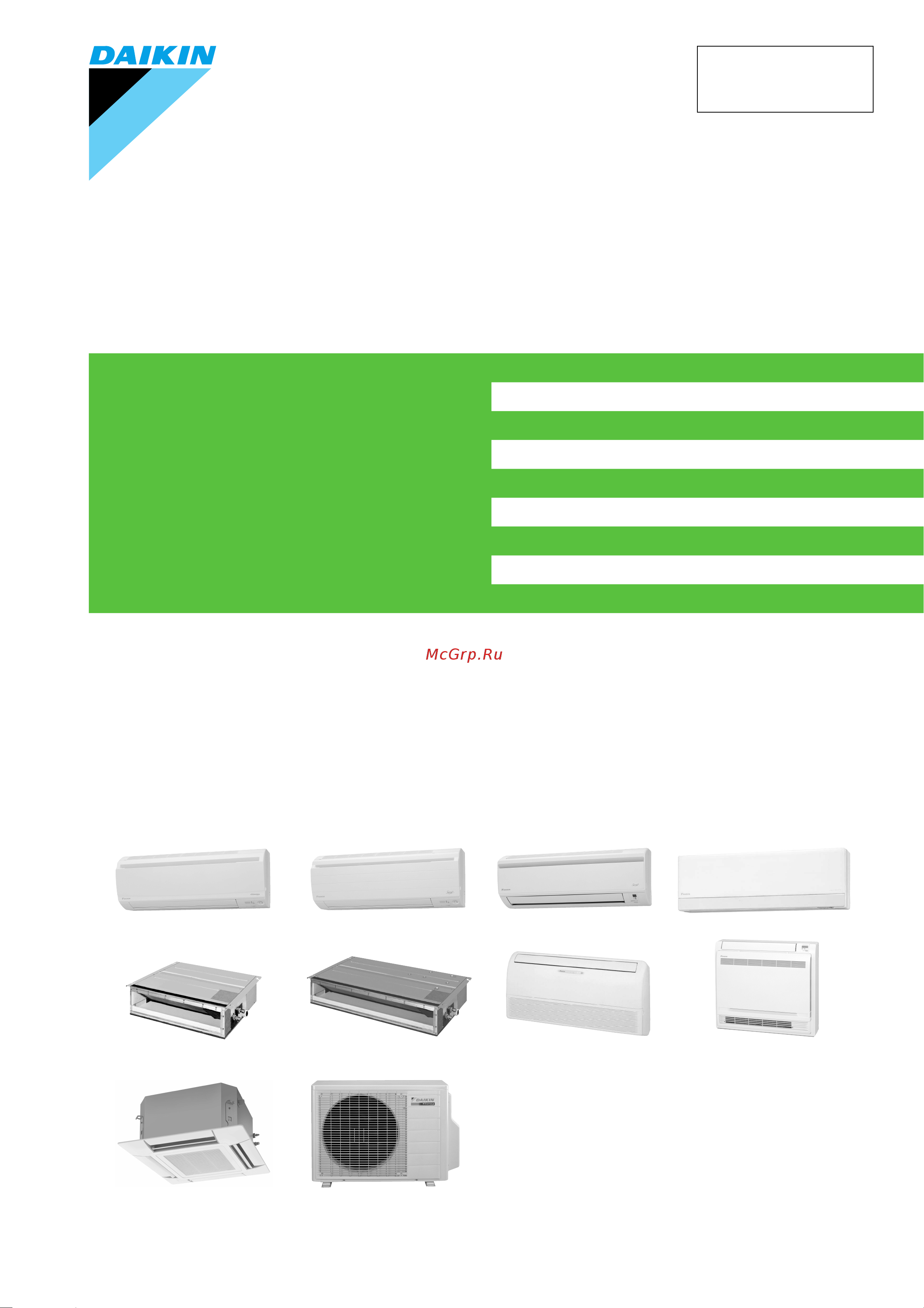
Inverter Multi for 2 Rooms
G-Series / H-Series
SiBE12-933_A
[Applied Models]
z Inverter Multi : Cooling Only
z Inverter Multi : Heat Pump
Содержание
- Inverter multi for 2 rooms g series h series 1
- Manual 1
- Service 1
- Sibe12 933_a 1
- Cooling only indoor unit 2
- Heat pump indoor unit 2
- Inverter multi for 2 rooms g series h series 2
- Outdoor unit 2
- Table of contents 2
- Control specification 9 3
- Function of thermistor 6 3
- Introduction v 3
- List of functions 3
- Main functions 6 3
- Part 1 list of functions 3
- Part 2 specifications 4 3
- Part 3 printed circuit board connector wiring diagram 5 3
- Part 4 function and control 5 3
- Printed circuit board connector wiring diagram 6 3
- Specifications 5 3
- Caution for diagnosis 64 2 problem symptoms and measures 66 3 service check function 67 4
- Instruction 7 4
- Part 5 operation manual 5 4
- Part 6 service diagnosis 63 4
- System configuration 6 4
- Troubleshooting 73 4
- Application of silicon grease to a power transistor and a diode bridge 64 5
- Check 12 5
- Field settings 55 5
- Outdoor unit 26 5
- Part 7 removal procedure 25 5
- Part 8 trial operation and field settings 49 5
- Part 9 appendix 65 5
- Piping diagrams 66 5
- Pump down operation 50 2 forced cooling operation mode 51 3 trial operation 52 5
- Wiring diagrams 72 5
- Cautions regarding safety of workers 6
- Introduction 6
- Safety cautions 6
- Warning 6
- Caution 7
- Warning 7
- Cautions regarding safety of users 8
- Warning 8
- Caution 9
- Warning 9
- Caution 10
- Icons are used to attract the attention of the reader to specific information the meaning of each icon is described in the table below 10
- Used icons 10
- List of functions 11
- Part 1 list of functions 11
- Cooling only models 12
- Holding functions no functions 12
- List of functions 12
- List of functions sibe12 933_a 12
- Holding functions no functions 13
- List of functions 3 13
- Sibe12 933_a list of functions 13
- Holding functions no functions 14
- List of functions 14
- List of functions sibe12 933_a 14
- Holding functions no functions 15
- List of functions 5 15
- Option 15
- Sibe12 933_a list of functions 15
- Holding functions no functions 16
- List of functions 16
- List of functions sibe12 933_a 16
- Heat pump models 17
- List of functions 7 17
- Sibe12 933_a list of functions 17
- List of functions 18
- List of functions sibe12 933_a 18
- List of functions 9 19
- Sibe12 933_a list of functions 19
- List of functions 20
- List of functions sibe12 933_a 20
- Holding functions no functions 21
- List of functions 11 21
- Sibe12 933_a list of functions 21
- Holding functions no functions 22
- List of functions 22
- List of functions sibe12 933_a 22
- Option 22
- Holding functions no functions 23
- List of functions 13 23
- Sibe12 933_a list of functions 23
- Part 2 specifications 24
- Specifications 5 24
- Indoor units cooling only 25
- Sibe12 933_a specifications 25
- Specifications 25
- Specifications 15 25
- Wall mounted type 50hz 220 230 240v 25
- Hz 220 230 240v 26
- Specifications 26
- Specifications sibe12 933_a 26
- Duct connected type 27
- Hz 230v 27
- Sibe12 933_a specifications 27
- Specifications 17 27
- Floor ceiling suspended dual type 28
- Hz 230v 28
- Specifications 28
- Specifications sibe12 933_a 28
- Floor standing type 29
- Hz 220 230 240v 29
- Sibe12 933_a specifications 29
- Specifications 19 29
- Ceiling mounted cassette type 50hz 230v 30
- Specifications 30
- Specifications sibe12 933_a 30
- Hz 220 240v 31
- Outdoor units cooling only 31
- Sibe12 933_a specifications 31
- Specifications 21 31
- Hz 220 240v 32
- Specifications 32
- Specifications sibe12 933_a 32
- Indoor units heat pump 33
- Sibe12 933_a specifications 33
- Specifications 23 33
- Wall mounted type 50hz 230v 33
- Hz 220 230 240v 34
- Specifications 34
- Specifications sibe12 933_a 34
- Hz 220 230 240v 35
- Sibe12 933_a specifications 35
- Specifications 25 35
- Hz 220 230 240v 36
- Specifications 36
- Specifications sibe12 933_a 36
- Hz 220 230 240v 37
- Sibe12 933_a specifications 37
- Specifications 27 37
- Hz 220 230 240v 38
- Specifications 38
- Specifications sibe12 933_a 38
- Duct connected type 39
- Hz 230v 39
- Sibe12 933_a specifications 39
- Specifications 29 39
- Floor ceiling suspended dual type 40
- Hz 230v 40
- Specifications 40
- Specifications sibe12 933_a 40
- Floor standing type 41
- Hz 220 230 240v 41
- Sibe12 933_a specifications 41
- Specifications 31 41
- Ceiling mounted cassette type 50hz 230v 42
- Specifications 42
- Specifications sibe12 933_a 42
- Hz 220 240v 43
- Outdoor units heat pump 43
- Sibe12 933_a specifications 43
- Specifications 33 43
- Hz 220 240v 44
- Specifications 44
- Specifications sibe12 933_a 44
- Part 3 printed circuit board connector wiring diagram 45
- Printed circuit board connector wiring diagram 6 45
- Atx20 35g 46
- Printed circuit board connector wiring diagram 46
- Wall mounted type 46
- Pcb 2 display pcb 47
- Pcb detail pcb 1 control pcb 47
- Printed circuit board connector wiring diagram 37 47
- Sibe12 933_a printed circuit board connector wiring diagram 47
- Ftxs20 50g atxs20 50g 48
- Pcb detail pcb 1 control pcb 49
- Printed circuit board connector wiring diagram 39 49
- Sibe12 933_a printed circuit board connector wiring diagram 49
- Pcb 2 signal receiver pcb pcb 3 display pcb 50
- Pcb 4 intelligent eye sensor pcb 50
- Printed circuit board connector wiring diagram 50
- Printed circuit board connector wiring diagram sibe12 933_a 50
- Ftxg25 35e ctxg50e atxg25 50e 51
- Pcb 2 signal receiver pcb 52
- Pcb 3 intelligent eye sensor pcb 52
- Pcb detail pcb 1 control pcb indoor unit 52
- Printed circuit board connector wiring diagram 52
- Printed circuit board connector wiring diagram sibe12 933_a 52
- Duct connected type 53
- Pcb 2 display pcb 54
- Pcb detail pcb 1 control pcb 54
- Printed circuit board connector wiring diagram 54
- Printed circuit board connector wiring diagram sibe12 933_a 54
- Floor ceiling suspended dual type 55
- Pcb 2 power supply pcb 56
- Pcb detail pcb 1 control pcb 56
- Printed circuit board connector wiring diagram 56
- Printed circuit board connector wiring diagram sibe12 933_a 56
- Pcb 3 display pcb 57
- Pcb 4 signal receiver pcb 57
- Printed circuit board connector wiring diagram 47 57
- Sibe12 933_a printed circuit board connector wiring diagram 57
- Floor standing type 58
- Pcb 2 control pcb 59
- Pcb 3 service pcb pcb 4 display pcb 59
- Pcb detail pcb 1 sensor pcb 59
- Printed circuit board connector wiring diagram 49 59
- Sibe12 933_a printed circuit board connector wiring diagram 59
- Ceiling mounted cassette type 600 600 60
- Pcb detail pcb 1 control pcb a1p 61
- Printed circuit board connector wiring diagram 51 61
- Sibe12 933_a printed circuit board connector wiring diagram 61
- Pcb 3 display pcb a4p 62
- Pcb detail pcb 2 signal receiver pcb a3p 62
- Printed circuit board connector wiring diagram 62
- Printed circuit board connector wiring diagram sibe12 933_a 62
- Outdoor units 63
- Pcb 1 control pcb 50 class 64
- Pcb detail pcb 1 control pcb 40 class 64
- Printed circuit board connector wiring diagram 64
- Printed circuit board connector wiring diagram sibe12 933_a 64
- Control specification 9 65
- Function of thermistor 6 65
- Main functions 6 65
- Part 4 function and control 65
- Frequency principle 66
- Main functions 66
- Temperature control 66
- Comfortable air conditioning a fine adjustment is integrated to keep the room temperature constant 67
- Drawing of inverter the following drawing shows a schematic view of the inverter principle 67
- Energy saving heating and cooling once the set temperature is reached the energy saving operation enables to maintain the room temperature at low power 67
- Even during extreme cold weather the high capacity is achieved it is maintained even when the outdoor temperature is 2 c 67
- Forced cooling operation for more information refer to forced cooling operation mode on page 67
- Frequency limits the following table shows the functions that define the minimum and maximum frequency 67
- Inverter features the inverter provides the following features 67
- Quick heating and quick cooling the compressor rotational speed is increased when starting the heating or cooling this enables to reach the set temperature quickly 67
- The regulating capacity can be changed according to the changes in the outdoor temperature and cooling heating load 67
- Power airflow flaps wide angle louvers auto swing comfort airflow mode and 3 d airflow 68
- Control flow 70
- D signal after the front panel starts moving 3 opening the flap fully after the front panel opens fully 4 making the fan rotate when the flap passes over the fan banned area 70
- F c a txg25 50e the system carries out the following control at the beginning to conduct every functional parts properly 1 opening the front panel fully 2 output of the 70
- Fan banned area the fan is prohibited to rotate until the flap angle exceeds certain level 70
- Function and control 70
- Main functions sibe12 933_a 70
- Operation starting control 70
- Timing chart 70
- Control mode phase control and fan speed control contains 9 steps lll ll sl l ml m mh h and hh the airflow rate can be automatically controlled depending on the difference between the room thermistor temperature and the target temperature this is done through phase control and hall ic control 71
- Fan speed control for indoor units 71
- Fan speed steps in automatic fan speed operation the step sl is not available 71
- For more information about hall ic refer to the troubleshooting for fan motor on page 177 71
- In case of atx20 35g 71
- Note 1 during powerful operation fan operate h tap 80 rpm 2 fan stops during defrost operation 3 the airconditioner does not operate with mh tap from a start of the auto fan speed operation for about 30 minutes 71
- Note 1 fan stops during defrost operation 2 in time of thermostat off the fan rotates at the following speed cooling the fan keeps rotating at the set tap heating 71
- The airflow rate is automatically controlled within this range when the fan setting button is set to automatic 71
- The fan keeps rotating at lll tap ftxs atxs and fvxs series or stops the other models 71
- Automatic airflow control for cooling 72
- Automatic airflow control for heating 72
- Function and control 72
- In case of atx20 35g 72
- Main functions sibe12 933_a 72
- On heating mode the indoor fan speed is regulated according to the indoor heat exchanger temperature and the difference between the room temperature and the required set point 72
- The following drawing explains the principle of fan speed control for cooling reference 72
- Detail the microcomputer automatically sets the temperature and airflow rate the difference between the room thermistor temperature at start up and the target temperature is divided into two zones then the unit operates in the dry mode with an appropriate capacity for each zone to maintain the temperature and humidity at a comfortable level 73
- Outline program dry operation removes humidity while preventing the room temperature from lowering since the microcomputer controls both the temperature and airflow rate the temperature adjustment and fan adjustment buttons are inoperable in this mode 73
- Program dry function 73
- Zone a thermostat off 73
- Zone b zone b 73
- Zone c thermostat on 73
- Automatic operation 74
- Cooling dry 75
- Duct connected type 75
- Floor ceiling suspended type 75
- Floor standing type 75
- Function and control 65 75
- Heating 75
- Sibe12 933_a main functions 75
- The monitoring time has passed while the temperature difference is in the zone b cooling dry 10 minutes heating 10 seconds 75
- The operation turns on in any zones except a 75
- The system resumes from defrost control in any zones except a 75
- The temperature difference is above the zone c after being in the zone a 75
- The temperature difference is in the zone a 75
- Thermostat control 75
- Thermostat control is based on the difference between the room temperature and the set point 75
- Thermostat off condition 75
- Thermostat on condition 75
- Wall mounted type 75
- Cooling operation wall mounted type floor standing type 76
- Duct connected type floor ceiling suspended dual type 76
- Function and control 76
- Heating operation 76
- Main functions sibe12 933_a 76
- Night set mode 76
- The night set circuit the night set mode continues operation at the target temperature for the first one hour then automatically raises the target temperature slightly in the case of cooling or lowers it slightly in the case of heating this prevents excessive cooling in summer and excessive heating in winter to ensure comfortable sleeping conditions and also conserves electricity 76
- When the off timer is set the night set mode is automatically activated the night set mode keeps the airflow rate setting 76
- Details 77
- Econo mode 77
- Econo mode can be activated while the unit is running the remote controller can send the econo command when the unit is in cool heat dry or auto operation 77
- Function and control 67 77
- Outline f a txs20 50g atx20 35g fvxs25 50f econo mode is a function that sets a limit for power consumption a maximum power consumption of 1000 w 40 class or 1300w 50 class is the limit for the 2mk x s40 50h and 2amx40 50g this mode is useful for preventing circuit breakers from being overloaded by the use of multiple air conditioners and other electrical devices the function is easily activated from the remote controller by pushing the econo button econo mode is available for all wall mounted models 77
- Sibe12 933_a main functions 77
- When the econo command is valid the input current is under reducing control also the upper limit of frequency is restricted 77
- A microcomputer in an indoor unit carries out a sampling every 20 msec and if it detects 10 cycles of the wave in one second in total corresponding to 20 msec 10 200 msec and when the on signal continues 3 seconds it judges human is in the room as the motion signal is on 78
- Area intelligent eye ftxs 78
- Function and control 78
- Intelligent eye sensor is divided into 2 areas and detects humans in each area 78
- Main functions sibe12 933_a 78
- Processing 1 detection method by intelligent eye 78
- The following functions can be performed by a human motion sensor intelligent eye 1 reduces the capacity when there is no human in the room in order to save electricity energy saving operation 2 divides the room into plural areas and detects existence of humans in each area shifts the airflow direction to the area having no human automatically to avoid direct airflow on humans 78
- This sensor detects human motion by receiving infrared rays and displays the pulse wave output 78
- Airflow direction in 2 area intelligent eye operation 79
- Detection method the opposite area of detected area is set as the target direction 79
- Detection signal on in both area a and b shift the airflow direction to area b left side 2 detection signal on in area a shift the airflow direction to area b left side 3 detection signal on in area b shift the airflow direction to area a right side 4 detection signal off in both area a and b no change 79
- Function and control 69 79
- In case of fan mode the fan speed reduces by 60 rpm 79
- Others 79
- Sibe12 933_a main functions 79
- The dry operation can not command the setting temperature with a remote controller but internally the set temperature is shifted by 1 c 79
- The motions in energy saving operation for example in cooling 79
- When a microcomputer does not have a signal from the sensor in 20 minutes it judges that nobody is in the room and operates the unit in temperature shifted 2 c from the set temperature cooling dry 2 c higher heating 2 c lower and auto according to the operation mode at that time 79
- When the detection signal off in both area a and b the unit starts energy saving operation 79
- A microcomputer in an indoor unit carries out a sampling every 20 msec and if it detects 10 cycles of the wave in one second in total corresponding to 20 msec 10 200 msec it judges human is in the room as the motion signal is on 80
- Function and control 80
- In case of fan mode the fan speed reduces by 50 rpm 80
- Intelligent eye atxs ftxg atxg ctxg 80
- Main functions sibe12 933_a 80
- Processing 1 detection method by intelligent eye 80
- The motions for example in cooling 80
- This is the function that detects existence of humans in the room by a human motion sensor intelligent eye and reduces the capacity when there is no human in the room in order to save electricity 80
- This sensor detects human motion by receiving infrared rays and displays the pulse wave output 80
- When a microcomputer does not have a signal from the sensor in 20 minutes it judges that nobody is in the room and operating the unit in temperature shifted 2 c from the set temperature cooling dry 2 c higher heating 2 c lower and auto according to the operation mode at that time 80
- Home leave operation 82
- Details of the control when powerful button is pushed in each operation mode the fan speed setting temperature is converted to the following states in a period of 20 minutes 83
- Ex powerful operation in cooling mode 83
- In case of f a txs20 50g 83
- Inverter powerful operation 83
- Outline in order to exploit the cooling and heating capacity to full extent operate the air conditioner by increasing the indoor fan rotating speed and the compressor frequency 83
- Refer to fan speed control on page 61 for detail 83
- Hot start function 84
- On off button on indoor unit 84
- Other functions 84
- Photocatalytic deodorizing filter 84
- Signal receiving sign 84
- Titanium apatite photocatalytic air purifying filter 84
- Air filter prefilter 85
- Air purifying filter 85
- Auto restart function 85
- Weekly timer operation 85
- Function of thermistor 86
- Heat pump model 86
- Cooling only model 88
- Control specification 89
- Detail 1 for heat pump model there are following modes stop cooling includes drying heating include defrosting 89
- For cooling only model there are following models stop and cooling including drying 89
- For the rooms set with different mode select standby mode operation lamp flashes 89
- Mode hierarchy 89
- Note unless specified otherwise an indoor dry operation command must be regarded as cooling operation determine operating mode judge the operating mode command set by each room in accordance with the instructing procedure and determine the operating mode of the system the following procedure is taken as the modes conflict with each other 89
- Outline there are two modes the mode selected in user s place normal air conditioning mode and forced operation mode for installation and providing service 89
- The system follows the mode determined first first push first set 89
- Frequency control 90
- Command frequency is determined in the following order of priority 1 limiting frequency by drooping function 91
- D signal 1 p control a total of the 91
- D signal and is used for frequency command 91
- D signal the difference between a room thermistor temperature and the target temperature is taken as the 91
- D value is calculated in each sampling time 20 seconds and the frequency is adjusted according to its difference from the frequency previously calculated 91
- D value is large increase the frequency 91
- D value is small lower the frequency when the 91
- D value of each room and a total value of q 91
- D value when the 91
- Determine lower limit frequency 91
- Determine prohibited frequency 91
- Determine upper limit frequency 91
- For cooling only model 1 determine command frequency 91
- I control if the operating frequency is not change more than a certain fixed time the frequency is adjusted according to the 91
- Indoor frequency command 91
- Input current discharge pipes freeze prevention dew prevention fin thermistor temperature 1 indoor frequency command 91
- Pi control determine frequency up down by 91
- Q of the operating room the room in which the thermostat is set to on q value indoor unit output determined from indoor unit volume airflow rate and other factors 91
- Set a maximum value as an lower limit frequency among the frequency lower limits of the following functions pressure difference upkeep 91
- Set a minimum value as an upper limit frequency among the frequency upper limits of the following functions compressor protection input current discharge pipes freeze prevention dew prevention fin thermistor temperature 91
- Th off thermostat off indoor unit capacity s value the capacity of the indoor unit is a s value and is used for frequency command 91
- There is a certain prohibited frequency such as a power supply frequency 91
- Values depend on the type of indoor unit 91
- When starting the compressor or when conditions are varied due to the change of the operating room the frequency must be initialized according to the total of a maximum 91
- 3 minute standby 93
- Controls at mode changing start up 93
- Four way valve operation compensation 93
- Four way valve switching 93
- Preheating operation 93
- Compressor protection function 94
- Control specification sibe12 933_a 94
- Function and control 94
- When turning the compressor from off to on the upper limit of frequency is set as follows the function is not used when defrosting 94
- Detail divide the zone 95
- Detail the frequency control is made within the following zones 95
- Discharge pipe temperature control 95
- Drooping zone start the timer and the frequency is drooping keep zone keep the upper limit of frequency 95
- Function and control 85 95
- Input current control 95
- Management within the zones 95
- Outline detect an input current by the ct during the compressor is running and set the frequency upper limit from such input current in case of heat pump model this control is the upper limit control function of the frequency which takes priority of the lower limit of four way valve activating compensation 95
- Outline the discharge pipe temperature is used as the compressor s internal temperature if the discharge pipe temperature rises above a certain level the operating frequency upper limit is set to keep this temperature from going up further 95
- Return reset zone cancel the upper limit of frequency 95
- Sibe12 933_a control specification 95
- The current droops when outdoor air temperature becomes higher than a certain level model by model 95
- The current droops when outdoor air temperature becomes higher than a certain level model by model 2 in case the operation mode is heating only for heat pump model 95
- When a stop current continues for 2 seconds after rushing on the stop zone the compressor operation stops if a drooping current is continues for 1 second after rushing on the drooping zone the frequency is 2 hz drooping repeating the above drooping continues until the current rushes on the drooping zone without change in the keep zone the frequency limit remains in the return reset zone the frequency limit is cancelled limitation of current drooping and stop value according to the outdoor air temperature 1 in case the operation mode is cooling 95
- Zone control contents stop zone when the temperature reaches the stop zone stop the compressor and correct abnormality 95
- Freeze up protection control 96
- Heating peak cut control 96
- Fan control 97
- Liquid compression protection function 2 97
- C according to the outdoor temperature 98
- Conditions for canceling defrost the target heat exchanger temperature as the canceling condition is selected in the range of 98
- Control specification sibe12 933_a 98
- Defrost control 98
- Detail conditions for starting defrost 98
- Function and control 98
- More than 30 minutes of accumulated time pass since the start of the operation or ending the previous defrosting 98
- Outline defrosting is carried out by the cooling cycle reverse cycle the defrosting time or outdoor heat exchanger temperature must be more than a certain value to finish 98
- The compressor operates for 6 minutes 98
- The starting conditions is determined with the outdoor temperature and the outdoor heat exchanger temperature 98
- The system is in heating operation 98
- Electronic expansion valve control 99
- Continue 100
- Control for abnormally high discharge pipe temperature 100
- Control of discharge pipe thermistor disconnection 100
- Control specification sibe12 933_a 100
- Control when frequency changed 100
- Cooling 1 room operation 100
- Cooling 2 rooms operation 100
- Defrost control fd 1 only for heat pump model 100
- Detail the followings are the examples of control which function in each mode by the electronic expansion valve control 100
- Dew buildup prevention control for indoor rotor 100
- Function 100
- Function and control 100
- Gas pipe isothermal control 100
- Heating 1 room operation 100
- Heating 2 rooms operation 100
- Indoor freeze prevention control 100
- Liquid pipe temperature control 100
- Not function 100
- Oil recovery control 100
- Only for heat pump model 100
- Open control when starting 100
- Operation pattern 100
- Pressure equalizing control 100
- Sc supercooling control only for heat pump model 100
- When power is turned on 100
- Disconnection of the discharge pipe thermistor 101
- Fully closing with power on 101
- Gas pipe isothermal control during cooling 101
- Opening limit 101
- Pressure equalization control 101
- Sc supercooling control 101
- Starting operation changing operating room control 101
- Control when frequency is changed 102
- High discharge pipe temperature 102
- Oil recovery function 102
- Target discharge pipe temperature control 102
- Detection of overload and overcurrent 103
- Malfunctions 103
- Refrigerant shortage control 103
- Sensor malfunction detection 103
- Additional function 104
- Powerful operation mode 104
- Preventing indoor freezing 104
- Voltage detection function 104
- Instruction 7 105
- Part 5 operation manual 105
- System configuration 6 105
- Operation instructions 106
- System configuration 106
- Atxs atx ftxg ctxg atxg fdk x s flk x s series 107
- Illustrations are for duct connected type fdk x s50c as representative 107
- Illustrations are for wall mounted type atxs20 50g as representative 107
- Illustrations are for wall mounted type ftxg25 35e as representative 107
- Instruction 107
- Manual contents and reference page 107
- Remote controller 108
- Atx 20 25 35 g 109
- Remote controller 109
- Ftxg 25 35 e atxg 25 35 50 e ctxg 50 e 110
- Remote controller 110
- Fdk x s 50 c fdk x s 25 35 ea 111
- Remote controller 111
- Flk x s 25 35 50 ba 112
- Remote controller 112
- Auto dry cool heat fan operation 113
- Press mode selector button and select a operation mode 113
- Press on off button 113
- Press on off button again 113
- Press temperature adjustment button 113
- To change the temperature setting 113
- To start operation 113
- To stop operation 113
- Press fan setting button 114
- To change the airflow rate setting 114
- Adjusting the airflow direction 115
- Press swing button 115
- To adjust the horizontal blades flaps 115
- To adjust the vertical blades louvers 115
- When the flaps have reached the desired position press swing button once more 115
- When the louvers have reached the desired position press the swing button once more 115
- Notes on flaps and louvers angles 116
- Press either the swing button or the swing button 116
- Press the swing button and the swing button the and display will light up and the flap and louvers will move in turn 116
- To cancel 3 d airflow 116
- To start 3 d airflow 116
- Adjusting the airflow direction 117
- Press swing button 117
- To adjust the horizontal blades flaps 117
- To adjust the vertical blades louvers 117
- When the flaps have reached the desired position press swing button once more 117
- Notes on comfort airflow operation 118
- Notes on flaps and louvers angles 118
- Press comfort airflow button 118
- Press comfort airflow button again 118
- To cancel comfort airflow operation 118
- To start comfort airflow operation 118
- Adjusting the air flow direction 119
- To 3 d airflow 119
- To adjust the horizontal blade flap 119
- To adjust the vertical blades louvers 119
- To cancel 3 d airflow 119
- Press comfort airflow button 120
- Press comfort airflow button again 120
- To cancel comfort airflow operation 120
- To start comfort airflow operation 120
- Adjusting the airflow direction 121
- Press swing button 121
- To adjust the horizontal blade flap 121
- When the flaps have reached the desired position press swing button once more 121
- Notes on flap and louvers angles 122
- To adjust the vertical blades louvers 122
- Comfort airflow operation 123
- Notes on comfort airflow operation 123
- Press comfort sensor button 123
- Press comfort sensor button and select on the lcd 123
- To cancel comfort airflow operation 123
- To start comfort airflow operation 123
- Powerful operation 124
- Press powerful button 124
- To cancel powerful operation 124
- To start powerful operation 124
- Outdoor unit quiet operation 125
- Press quiet button 125
- To cancel outdoor unit quiet operation 125
- To start outdoor unit quiet operation 125
- Econo operation 126
- To cancel econo operation 126
- To start econo operation 126
- Econo operation 127
- To cancel econo operation 127
- To start econo operation 127
- Before using home leave operation 128
- Home leave operation 128
- Press home leave button 128
- Press home leave button again 128
- To cancel home leave operation 128
- To start home leave operation 128
- Use as a favorite mode 129
- Use as an energy saving mode 129
- Useful in these cases 129
- What s the home leave operation 129
- Intelligent eye operation 130
- Press comfort sensor button 130
- Press comfort sensor button and select on the lcd 130
- To cancel the intelligent eye operation 130
- To start intelligent eye operation 130
- Caution 131
- Intelligent eye is useful for energy saving 131
- Intelligent eye operation 131
- Notes on intelligent eye 131
- Press comfort sensor button 131
- Press comfort sensor button and select on the lcd 131
- To combine comfort airflow operation and intelligent eye operation 131
- Intelligent eye operation 132
- Press sensor button 132
- Press sensor button again 132
- To cancel the intelligent eye operation 132
- To start intelligent eye operation 132
- Caution 133
- Intelligent eye is useful for energy saving 133
- Notes on intelligent eye 133
- Press cancel button 134
- Press off timer button 0 0 134
- Press off timer button again 134
- Press timer setting button until the time setting reaches the point you like 134
- Timer operation 134
- To cancel the off timer operation 134
- To use off timer operation 134
- Attention 135
- Press cancel button 135
- Press on timer button 6 0 135
- Press on timer button again 135
- Press timer setting button until the time setting reaches the point you like 135
- To cancel on timer operation 135
- To combine on timer and off timer 135
- To use on timer operation 135
- Night quiet mode available only for cooling operation 136
- Note for multi system 136
- Outdoor unit quiet operation 136
- Selecting the operation mode 136
- Note for multi system 137
- Operation mode priority 137
- Priority room setting 137
- Priority when powerful operation is used 137
- Priority when using outdoor unit quiet operation 137
- Ftxs fvxs series 138
- Illustrations are for wall mounted type ftxs20 50g as representative 138
- Instruction sibe12 933_a 138
- Manual contents and reference page 138
- Operation manual 138
- Remote controller 139
- Fvxs 25 35 50 f 140
- Remote controller 140
- Auto dry cool heat fan operation 141
- Press mode selector button and select a operation mode 141
- Press on off button 141
- Press on off button again 141
- Press temperature adjustment button 141
- To change the temperature setting 141
- To start operation 141
- To stop operation 141
- Press fan setting button 142
- To change the airflow rate setting 142
- Adjusting the airflow direction 143
- Press swing button 143
- To adjust the horizontal blades flaps 143
- To adjust the vertical blades louvers 143
- When the flaps have reached the desired position press swing button once more 143
- When the louvers have reached the desired position press the swing button once more 143
- Comfort airflow operation 144
- Notes on flaps and louvers angles 144
- Press either the swing button or the swing button 144
- Press the swing button and the swing button the and display will light up and the flap and louvers will move in turn 144
- To cancel 3 d airflow 144
- To start 3 d airflow 144
- Adjusting the airflow direction 145
- Notes on flap and louvers angle 145
- Press swing button 145
- To adjust the horizontal blade flap 145
- To adjust the vertical blades louvers 145
- When the flap has reached the desired position press swing button once more 145
- Airflow selection 146
- Caution 146
- When setting the air outlet selection switch to 146
- When setting the airflow selection switch to 146
- Comfort airflow and intelligent eye operation 147
- Press comfort sensor button 147
- Press comfort sensor button and select an operation mode 147
- To cancel operation 147
- To start operation 147
- Notes on comfort airflow operation 148
- Notes on intelligent eye operation 148
- Caution 149
- Comfort airflow and intelligent eye operation 149
- Intelligent eye is useful for energy saving 149
- Notes on intelligent eye operation 149
- To combine comfort airflow operation and intelligent eye operation 149
- Powerful operation 150
- Press powerful button 150
- Press powerful button again 150
- To cancel powerful operation 150
- To start powerful operation 150
- Outdoor unit quiet operation 151
- Press quiet button 151
- Press quiet button again 151
- To cancel outdoor unit quiet operation 151
- To start outdoor unit quiet operation 151
- Econo operation 152
- Press econo button 152
- Press econo button again 152
- To cancel econo operation 152
- To start econo operation 152
- Press cancel button 153
- Press off timer button 0 0 153
- Press off timer button again 153
- Press select button until the time setting reaches the point you like 153
- Timer operation 153
- To cancel the off timer operation 153
- To use off timer operation 153
- Attention 154
- Press cancel button 154
- Press on timer button 6 0 154
- Press on timer button again 154
- Press select button until the time setting reaches the point you like 154
- To cancel on timer operation 154
- To combine on timer and off timer 154
- To use on timer operation 154
- Example 155
- Using in these cases of weekly timer 155
- Weekly timer operation 155
- Press button 156
- Press next button 156
- Press select button to select the desired mode 156
- Press select button to select the desired time 156
- Press the select button to select the desired day of the week and reservation number 156
- To use weekly timer operation 156
- Press button to complete the setting 157
- Press next button 157
- Press select button to select the desired temperature 157
- Weekly timer operation 157
- Press button 158
- Press button 2 press select button to confirm the day of the week to be copied 3 press copy button 158
- Press select button to select the destination day of the week 5 press copy button 158
- Using copy mode 158
- Canceling all reservations 159
- Canceling individual reservations 159
- Confirming a reservation 159
- Hold the weekly button for 5 seconds 159
- Press button 159
- Press weekly button to deactivate the weekly operation 159
- Select the day of the week to be canceled with the select button 6 hold the weekly button for 5 seconds 159
- To cancel weekly timer operation 159
- Weekly timer operation 159
- Night quiet mode available only for cooling operation 160
- Note for multi system 160
- Outdoor unit quiet operation 160
- Selecting the operation mode 160
- Note for multi system 161
- Operation mode priority 161
- Priority room setting 161
- Priority when powerful operation is used 161
- Priority when using outdoor unit quiet operation 161
- Ffq series 162
- Names and functions of parts 163
- Precautions for group control system or two remote controller control system 163
- What to do before operation 163
- Caution 164
- Safety considerations 164
- Warning 164
- Installation site 165
- Operation range 165
- Name and function of each switch and display on the remote controller 166
- Operation procedure 166
- Adjustment 167
- Air flow direction adjust 167
- Cooling heating automatic fan and program dry operation 167
- Defrost operation 167
- Explanation of heating operation 167
- On off fan speed control 167
- Operation mode selector 167
- Press on off button 167
- Press operation mode selector button several times and select the operation mode of your choice as follows 167
- Press temperature setting button and program the setting temperature 167
- Regarding outside air temperature and heating capacity 167
- Temperature setting 167
- Optimum operation 168
- Press the air flow direction adjust button to select the air direction as following 168
- Press the programming time button and set the time for stopping or starting the system 168
- Press the timer mode start stop button several times and select the mode on the display 168
- Press the timer on off button movement of the air flow flap 168
- Program timer operation 168
- Programming time 168
- Timer mode start stop 168
- Timer on off 168
- Before obtaining access to terminal devices all power supply circuits must be interrupted 169
- How to clean the air filter 169
- Important 169
- Maintenance for service personnel 169
- Only a qualified service person is allowed to perform maintenance 169
- How to clean air outlet and outside panels 170
- How to clean the suction grille 170
- Not malfunction of the air conditioner 170
- Start up after a long stop 170
- What to do when stopping the system for a long period 170
- Trouble shooting 172
- Warning 172
- Caution for diagnosis 64 2 problem symptoms and measures 66 3 service check function 67 173
- Check 12 173
- Part 6 service diagnosis 173
- Troubleshooting 73 173
- Caution for diagnosis 174
- Problem symptoms and measures 176
- Arc433 series 177
- Check method 1 1 when the timer cancel button is held down for 5 seconds 177
- Indication appears on the temperature display section 177
- Note 1 a short beep pi and two consecutive beeps pi pi indicate non corresponding codes 2 to return to the normal mode hold the timer cancel button down for 5 seconds when the remote controller is left untouched for 60 seconds it also returns to the normal mode 177
- Press the timer cancel button repeatedly until a long beep sounds 177
- Service check function 177
- Arc452 series 180
- Check method 1 1 when the timer cancel button is held down for 5 seconds 180
- Indication appears on the temperature display section 180
- Note 1 a short beep pi and two consecutive beeps pi pi indicate non corresponding codes 2 to return to the normal mode hold the timer cancel button down for 5 seconds when the remote controller is left untouched for 60 seconds it also returns to the normal mode 180
- Press the timer cancel button repeatedly until a long beep sounds 180
- The code indication changes in the sequence shown below 180
- Displayed only when system down occurs 183
- Error codes and description 183
- Troubleshooting 183
- Indoor unit pcb abnormality 184
- Freeze up protection control or high pressure control 185
- Caution be sure to turn off power switch before connect or disconnect connector or parts damage may be occurred 186
- Check no 6 refer to p 15 186
- Service diagnosis 186
- Troubleshooting 186
- Troubleshooting sibe12 933_a 186
- Ac motor 187
- Check no 6 refer to p 21 187
- Detection error due to faulty control pcb 187
- Fan motor or related abnormality 187
- Malfunction decision conditions 187
- Method of malfunction detection 187
- Operation halt due to breaking of the fan motor lead wires 187
- Operation halt due to breaking of wire inside the fan motor 187
- Operation halt due to faulty capacitor of the fan motor 187
- Operation halt due to short circuit inside the fan motor winding 187
- Remote controller display 187
- Supposed causes 187
- The rotation speed detected by the hall ic during fan motor operation is used to determine abnormal fan motor operation 187
- Troubleshooting 187
- When the detected rotation speed does not reach the demanded rotation speed of the target tap and is less than 50 of the maximum fan motor rotation speed 187
- Dc motor 188
- Caution be sure to turn off power switch before connect or disconnect connector or parts damage may be occurred 189
- Check no 1 refer to p 12 189
- Service diagnosis 179 189
- Sibe12 933_a troubleshooting 189
- Troubleshooting f a txs20 50g f c a txg25 50e fvxs25 50f 189
- Atx20 35g 190
- Caution be sure to turn off power switch before connect or disconnect connector or parts damage may be occurred 190
- Check no 0 refer to p 24 190
- Check no 8 refer to p 22 190
- Check no 9 refer to p 23 190
- Service diagnosis 190
- Troubleshooting sibe12 933_a 190
- Thermistor or related abnormality indoor unit 191
- 1 pull the plug out or turn the breaker off 2 remove the decorative plate 3 remove the slot in panel 4 put the plug in or turn the breaker on wait until the initialization finishes 5 operate the unit by the indoor unit on off switch 192
- Front panel open close fault 192
- Malfunction decision conditions 192
- Malfunction of the limit switch 192
- Malfunction of the reduction motor 192
- Malfunction or deterioration of the front panel mechanism 192
- Method of malfunction detection 192
- Remote controller display 192
- Supposed causes 192
- The system is shut down when the error occurs twice 192
- Troubleshooting 192
- Freeze up protection control 193
- Caution be sure to turn off power switch before connect or disconnect connector or parts damage may be occurred 194
- Check no 4 refer to p 13 194
- Check no 6 refer to p 15 194
- Service diagnosis 194
- Troubleshooting 194
- Troubleshooting sibe12 933_a 194
- A compressor overload is detected through compressor ol 195
- Check no 1 refer to p 18 195
- Check no 4 refer to p 13 195
- Check no 5 refer to p 14 195
- Check no 6 refer to p 15 195
- Electronic expansion valve defective 195
- Four way valve malfunctioning 195
- If the compressor ol is activated twice the system is shut down 195
- Malfunction decision conditions 195
- Method of malfunction detection 195
- Ol activation compressor overload 195
- Outdoor unit pcb defective 195
- Refrigerant shortage 195
- Remote controller display 195
- Stop valve defective 195
- Supposed causes 195
- The error counter is reset if this or any other error does not occur during the following 60 minute compressor running time total time 195
- The operating temperature condition is not specified 195
- Troubleshooting 195
- Water mixed in the local piping 195
- Check no 4 refer to p 19 196
- Clearing condition continuous run for about 11 minutes normal 196
- Compressor lock 196
- Compressor locked 196
- Disconnection of compressor harness 196
- Judging from current waveform generated when high frequency voltage is applied to the compressor 196
- Malfunction decision conditions 196
- Method of malfunction detection 196
- Remote controller display 196
- Supposed causes 196
- The system is shut down if the error occurs 16 times 196
- Troubleshooting 196
- Dc fan lock 197
- Input overcurrent detection 198
- An input overcurrent may result from wrong internal wiring if the wires have been disconnected and reconnected for part replacement for example and the system is interrupted by an input overcurrent check the wires again 199
- Caution be sure to turn off power switch before connect or disconnect connector or parts damage may be occurred 199
- Check no 4 refer to p 19 199
- Check no 7 refer to p 16 199
- Check no 8 refer to p 17 199
- Service diagnosis 189 199
- Sibe12 933_a troubleshooting 199
- Troubleshooting 199
- Discharge pipe temperature control 200
- High pressure control in cooling 201
- Caution be sure to turn off power switch before connect or disconnect connector or parts damage may be occurred 202
- Check no 4 refer to p 13 202
- Check no 6 refer to p 15 202
- Check no 7 refer to p 16 202
- Check no 9 refer to p 17 202
- Service diagnosis 202
- Troubleshooting 202
- Troubleshooting sibe12 933_a 202
- Compressor sensor system abnormality 203
- Position sensor abnormality 204
- Caution be sure to turn off power switch before connect or disconnect connector or parts damage may be occurred 205
- Check no 3 refer to p 18 205
- Check no 4 refer to p 19 205
- Check no 8 refer to p 17 205
- Service diagnosis 195 205
- Sibe12 933_a troubleshooting 205
- Troubleshooting 205
- Dc voltage dc current sensor abnormality 206
- Thermistor or related abnormality outdoor unit 207
- Caution be sure to turn off power switch before connect or disconnect connector or parts damage may be occurred 208
- Check no 6 refer to p 15 208
- Discharge pipe thermistor 208
- Gas pipe thermistor 208
- Liquid pipe thermistor 208
- Outdoor temperature thermistor 208
- Outdoor unit heat exchanger thermistor 208
- Radiation fin thermistor 208
- Service diagnosis 208
- Troubleshooting 208
- Troubleshooting sibe12 933_a 208
- Electrical box temperature rise 209
- Caution be sure to turn off power switch before connect or disconnect connector or parts damage may be occurred 210
- Check no 6 refer to p 15 210
- Check no 7 refer to p 16 210
- Check no 9 refer to p 17 210
- Precaution before turning on the power again make sure the power has been off for at least 30 seconds 210
- Service diagnosis 210
- Troubleshooting 210
- Troubleshooting sibe12 933_a 210
- Radiation fin temperature rise 211
- Caution be sure to turn off power switch before connect or disconnect connector or parts damage may be occurred 212
- Check no 6 refer to p 15 212
- Check no 7 refer to p 16 212
- Check no 9 refer to p 17 212
- Note refer to application of silicon grease to a power transistor and a diode bridge on p 64 212
- Service diagnosis 212
- Troubleshooting 212
- Troubleshooting sibe12 933_a 212
- Output overcurrent detection 213
- Caution be sure to turn off power switch before connect or disconnect connector or parts damage may be occurred 214
- Check no 3 refer to p 18 214
- Check no 4 refer to p 19 214
- Check no 7 refer to p 16 214
- Check no 8 refer to p 17 214
- Service diagnosis 214
- Troubleshooting 214
- Troubleshooting sibe12 933_a 214
- Refrigerant shortage 215
- Caution be sure to turn off power switch before connect or disconnect connector or parts damage may be occurred 216
- Check no 4 refer to p 13 216
- Check no 6 refer to p 15 216
- Service diagnosis 216
- Troubleshooting 216
- Troubleshooting sibe12 933_a 216
- An abnormal voltage rise or drop is detected by checking the over voltage detection circuit or dc voltage detection circuit 217
- An over voltage signal is fed from the over voltage detection circuit to the microcomputer or the voltage being detected by the dc voltage detection circuit is judged to be below 150v for 0 second 217
- Clearing condition continuous run for about 60 minutes normal 217
- Malfunction decision conditions 217
- Method of malfunction detection 217
- Over voltage detection low voltage detection 217
- Over voltage detector or dc voltage detection circuit defective 217
- Pam control part s defective 217
- Remote controller display 217
- Short circuit inside the fan motor winding 217
- Supply voltage not as specified 217
- Supposed causes 217
- The system is shut down if the error occurs 255 times 217
- Troubleshooting 217
- Anti icing function in other rooms unspecified voltage between indoor and outdoor units 218
- Outdoor unit pcb abnormality or signal transmission circuit abnormality 219
- Caution be sure to turn off power switch before connect or disconnect connector or parts damage may be occurred 220
- Service diagnosis 220
- Troubleshooting 220
- Troubleshooting sibe12 933_a 220
- Check no 0 refer to p 17 221
- Service diagnosis 211 221
- Sibe12 933_a troubleshooting 221
- Check no 1 1 check connector connection 2 check motor power supply voltage output pins 4 7 3 check motor control voltage pins 4 3 4 check rotation command voltage output pins 4 2 5 check rotation pulse input pins 4 1 222
- Fan motor connector output check 222
- How to check 222
- Check no 4 conduct the followings to check the electronic expansion valve ev 1 check to see if the ev connector is correctly inserted in the pcb match the ev unit number and the connector number 2 turn the power off and on again and check to see if all the evs generate latching sound 3 if any of the evs does not generate latching sound in the above step 2 disconnect that connector and check the continuity using a tester check the continuity between the pins 1 6 and 3 6 and between the pins 2 5 and 4 5 if there is no continuity between the pins the ev coil is faulty 4 if no ev generates latching sound in the above step 2 the outdoor unit pcb is faulty 5 if the continuity is confirmed in the above step 3 mount a good coil which generated latching sound in the ev unit that did not generate latching sound and check to see if that ev generates latching sound 223
- Electronic expansion valve check 223
- If latching sound is generated the outdoor unit pcb is faulty 223
- If latching sound is not generated the ev unit is faulty 223
- If the system keeps operating with a defective electronic expansion valve the following problem may occur 223
- Note please note that the latching sound varies depending on the valve type 223
- Check no 5 224
- Check sibe12 933_a 224
- Four way valve performance check 224
- Service diagnosis 224
- Check no 6 remove the connectors of the thermistors on the pcb and measure the resistance of each thermistor using tester the relationship between normal temperature and resistance is shown in the graph and the table below 225
- Thermistor resistance check 225
- Check no 7 226
- Check sibe12 933_a 226
- Installation condition check 226
- Service diagnosis 226
- Check no 0 measure the power supply waveform between pins 1 and 2 on the terminal board and check the waveform disturbance 227
- Check no 8 227
- Check no 9 227
- Check to see if the power supply waveform is a sine wave fig 227
- Check to see if there is waveform disturbance near the zero cross sections circled in fig 227
- Discharge pressure check 227
- Fig fig 227
- Outdoor unit fan system check with dc motor 227
- Power supply waveforms check 227
- Service diagnosis 217 227
- Sibe12 933_a check 227
- Check no 1 228
- Check no 3 228
- Disconnect the compressor harness connector from the outdoor unit pcb to disengage the connector press the protrusion on the connector 228
- Follow the procedure below to measure resistance between the terminals of the db1 and the terminals of the compressor with a multi tester evaluate the measurement results for a judgment 228
- Inverter units refrigerant system check 228
- Note check to make sure that the voltage between and of the diode bridge db1 is approx 0 v before checking 228
- Power transistor check 228
- Inverter checker check 229
- Hall ic check 231
- Rotating pulse input on the outdoor unit pcb check 231
- Check no 8 1 check the connector for connection 2 check the motor power voltage is generated between pins 2 and 3 232
- Check sibe12 933_a 232
- Indoor pcb output check 232
- Service diagnosis 232
- Check no 9 1 check the connector for connection 2 turn the power on and stop the operation 3 check if the hall ic generates the rotation pulse 4 times when the fan motor is manually rotated once between the pins 1 and 3 233
- Service diagnosis 223 233
- Sibe12 933_a check 233
- Turning speed pulse on the indoor unit pcb check 233
- Between the pins 12 9 and between 9 6 234
- Check no 0 1 check the connector for connection 2 turn the power off 3 check if each resistance at the phases u v and v w is 10 234
- Check sibe12 933_a 234
- Fan motor wire short circuit check 234
- Service diagnosis 234
- Outdoor unit 26 235
- Part 7 removal procedure 235
- External appearance 236
- Outdoor unit 236
- Procedure warning be sure to wait 10 minutes or more after turning off all power supplies before disassembling work 236
- Removal of the panels and plates 236
- Remove the 2 screws right left of the top panel and 8 screws to remove the front panel 236
- The bell mouth can not be removed 236
- The front panel has 4 hooks 236
- Removal of the electrical box 238
- Lift up the electrical box to remove 242
- Remove the screw in front of the electrical box 242
- Removal of the pcb 243
- Cut off the clamp and disconnect the wire harnesses 244
- Remove the 2 screws and release the one clip to remove the radiation shield plate 244
- The clip is push mount type 244
- Remove the 2 screws of the radiation fin 247
- Removal of the sound blanket 248
- Removal of the outdoor fan fan motor 250
- Removal of the thermistors 253
- Removal of the compressor 255
- Removal of the four way valve electronic expansion valve 257
- Application of silicon grease to a power transistor and a diode bridge 64 259
- Field settings 55 259
- Part 8 trial operation and field settings 259
- Pump down operation 50 2 forced cooling operation mode 51 3 trial operation 52 259
- Pump down operation 260
- Detail 261
- Ex wall mounted type g series 261
- Forced cooling operation mode 261
- Outline forced operation mode includes only forced cooling 261
- 2 3 4 1 5 262
- Indoor unit atx atxs atxg f c txg ftxs fdk x s flk x s fvxs series 262
- Trial operation 262
- Check that the temperature setting of the remote controller is at the lowest level in cooling mode or use trial operation mode 264
- Checkpoints for trial operation 264
- Go through the following checklist 264
- Indoor unit ffq series 264
- Open the gas stop valve 2 open the liquid stop valve 3 electrify for 6 hours 4 set to cooling operation with the remote controller and start operation by pressing on off button 5 press the inspection test button 4 times 2 times for wireless remote controller and operate at trial operation mode for 3 minutes 6 press the airflow direction adjust button to make sure the unit is in operation 7 press the inspection test button and operate normally 8 confirm all the function of unit according to the operation manual 9 if the decoration panel has not been installed turn off the power after the trial operation 264
- To carry out a trial operation check the following 264
- Trial operation 264
- Field settings 265
- Model type setting 265
- Ra indoor unit atx atxs atxg f c txg ftxs fdk x s flk x s fvxs series 265
- When 2 units are installed in 1 room 265
- 1 remove the front grille 2 lift the sensor pcb fixing plate and remove the front shield plate 3 disconnect the connectors s1 s41 s42 4 remove the electric box 1 screw 5 pull out the indoor heat exchanger thermistor 6 remove the shield plate 8 tabs 7 cut the address jumper ja on the indoor unit pcb 8 cut the address jumper j4 in the remote controller refer to wireless remote controller 266
- Address 266
- Address ja 266
- Field settings sibe12 933_a 266
- G series 266
- Trial operation and field settings 266
- Cut the jumper ja on pcb 267
- Sibe12 933_a field settings 267
- Trial operation and field settings 257 267
- Wireless remote controller 1 remove the cover and take it off 2 cut the address setting jumper 267
- For the location of the jumper and the switch refer to the following pages wall mounted type page 37 39 42 floor standing type page 49 floor ceiling suspended dual type page 46 duct connected type page 44 268
- Jumper and switch settings 268
- How to change the field settings with the wired remote controller 269
- Indoor unit ffq series 269
- How to change the field settings with the wireless remote controller 270
- Factory setting 271
- Main sub setting when using two remote controllers 271
- Overview of the field settings 271
- Setting the remote controllers are factory set to main so you only have to change one remote controller from main to sub to change a remote controller from main to sub proceed as follows 271
- Situation the main sub setting is necessary when one indoor unit is controlled by two remote controllers when you use two remote controllers control panel and separate remote controller set one to main and the other to sub you can do this by setting the switch on the remote controller s pcb 271
- Jumper settings 272
- Location of the jumpers 272
- Outdoor unit 272
- Detail 273
- Maximum power input limitation setting 273
- Outline 273
- Sibe12 933_a field settings 273
- The maximum power input limitation needs to be set when the unit is installed 273
- This function is recommended for areas with circuit breakers of low capacity 273
- This function limits the power input of the unit to 1700w 273
- Trial operation and field settings 263 273
- Application of silicon grease to a power transistor and a diode bridge 274
- Diode bridge diode bridge rectifier stack etc 274
- Ng foreign object ok evenly applied silicon grease ng not evenly applied 274
- Not applied paper waste 274
- Power transistor trm tpm igbt ipm spm etc 274
- Take out a pcb 274
- Part 9 appendix 275
- Piping diagrams 66 275
- Wiring diagrams 72 275
- Atx20 25 35gv1b ftxs20 25 35 42g2v1b atxs20 25 35 42g2v1b 276
- Ftxs50g2v1b atxs50g2v1b ftxg25 35ev1bw s atxg25 35ev1b 276
- Indoor units 276
- Piping diagrams 276
- Wall mounted type 276
- Appendix 267 277
- C 4d045449k 277
- Ctxg50ev1bw s atxg50ev1b 277
- Duct connected type 277
- Fdks50cvmb fdks25eavmb fdks35eavmb fdxs50cvmb fdxs25eavmb fdxs35eavmb 277
- Sibe12 933_a piping diagrams 277
- Appendix 278
- D034012e 278
- D048724b 278
- Flks25bavmb flks35bavmb flks50bavmb 278
- Floor ceiling suspended dual type 278
- Flxs25bavmb flxs35bavmb flxs50bavmb 278
- Piping diagrams sibe12 933_a 278
- Appendix 269 279
- Ceiling mounted cassette type 279
- Ffq25b8v1b ffq35b8v1b ffq50b8v1b 279
- Floor standing type 279
- Fvxs25fv1b fvxs35fv1b fvxs50fv1b 279
- Sibe12 933_a piping diagrams 279
- Appendix 280
- Cooling only 280
- Mks40h2v1b 280
- Mks50h2v1b 280
- Outdoor units 280
- Piping diagrams sibe12 933_a 280
- Amx40g2v1b 2mxs40h2v1b 281
- Amx50g2v1b 2mxs50h2v1b 281
- Appendix 271 281
- D055808d 281
- D057467e 281
- Heat pump 281
- Sibe12 933_a piping diagrams 281
- Atx20 25 35gv1b 282
- Ftxs20 25 35 42 50g2v1b atxs20 25 35 42 50g2v1b 282
- Indoor units 282
- Wall mounted type 282
- Wiring diagrams 282
- Appendix 273 283
- D050493b 283
- Ftxg25 35ev1bw s ctxg50ev1bw s atxg25 35 50ev1b 283
- Sibe12 933_a wiring diagrams 283
- Appendix 284
- Duct connected type 284
- Fdks50cvmb fdks25eavmb fdks35eavmb fdxs50cvmb fdxs25eavmb fdxs35eavmb 284
- Flks25bavmb flks35bavmb flks50bavmb flxs25bavmb flxs35bavmb flxs50bavmb 284
- Floor ceiling suspended dual type 284
- Wiring diagrams sibe12 933_a 284
- Appendix 275 285
- D055953a 285
- Floor standing type 285
- Fvxs25fv1b fvxs35fv1b fvxs50fv1b 285
- Sibe12 933_a wiring diagrams 285
- Appendix 286
- Ceiling mounted cassette type 286
- D038357b 286
- Ffq25b8v1b ffq35b8v1b ffq50b8v1b 286
- Wiring diagrams sibe12 933_a 286
- Appendix 277 287
- Cooling only 287
- Mks40h2v1b 287
- Mks50h2v1b 287
- Outdoor units 287
- Sibe12 933_a wiring diagrams 287
- Amx40g2v1b 2mxs40h2v1b 288
- Amx50g2v1b 2mxs50h2v1b 288
- Appendix 288
- D055486d 288
- D057045d 288
- Heat pump 288
- Wiring diagrams sibe12 933_a 288
- Air conditioners should not be installed in areas where corrosive gases such as acid gas or alkaline gas are produced 2 if the outdoor unit is to be installed close to the sea shore direct exposure to the sea breeze should be avoided if you need to install the outdoor unit close to the sea shore contact your local distributor 289
- Ask a qualified installer or contractor to install this product do not try to install the product yourself improper installation can result in water or refrigerant leakage electrical shock fire or explosion 289
- Cautions on product corrosion 289
- Daikin industries ltd s products are manufactured for export to numerous countries throughout the world daikin industries ltd does not have control over which products are exported to and used in a particular country prior to purchase please therefore confirm with your local authorised importer distributor and or retailer whether this product conforms to the applicable standards and is suitable for use in the region where the product will be used this statement does not purport to exclude restrict or modify the application of any local legislation 289
- Http www daikin com global_ac 289
- If you have any enquiries please contact your local importer distributor and or retailer 289
- Read the user s manual carefully before using this product the user s manual provides important safety instructions and warnings be sure to follow these instructions and warnings 289
- Sibe12 933_a printed in japan 12 2010 b ak 289
- Use only those parts and accessories supplied or specified by daikin ask a qualified installer or contractor to install those parts and accessories use of unauthorised parts and accessories or improper installation of parts and accessories can result in water or refrigerant leakage electrical shock fire or explosion 289
- Warning 289
Похожие устройства
- Daikin 2MXS50H3V1B2 Инструкция по монтажу
- Daikin 3MXM40N2V1B Руководство по эксплуатации
- Daikin 3MXM40N2V1B Инструкция по монтажу
- Daikin 3MXM40N2V1B Руководство по монтажу
- Daikin 3MXM52N2V1B Руководство по эксплуатации
- Daikin 3MXM52N2V1B Инструкция по монтажу
- Daikin 3MXM52N2V1B Справочное руководство для монтажника
- Daikin 3MXM68N2V1B Руководство по эксплуатации
- Daikin 3MXM40N2V1B Справочное руководство для монтажника
- Daikin 3MXM68N2V1B Инструкция по монтажу
- Daikin 3MXM52N2V1B Руководство по монтажу
- Daikin 3MXM68N2V1B Руководство по монтажу
- Daikin 3MXM68N2V1B Справочное руководство для монтажника
- Daikin 3MXM40N2V1B7 Справочное руководство для монтажника
- Daikin 3MXM40N2V1B7 Инструкция по монтажу
- Daikin 3MXM52N2V1B7 Справочное руководство для монтажника
- Daikin 3MXM52N2V1B7 Инструкция по монтажу
- Daikin 3MXM40N2V1B8 Справочное руководство для монтажника
- Daikin 3MXM40N2V1B8 Инструкция по монтажу
- Daikin 3MXM52N2V1B8 Инструкция по монтажу
Скачать
Случайные обсуждения