
Daikin 2MX52HV1NB Сервис мануал онлайн
SiE00-04
Table of Contents i
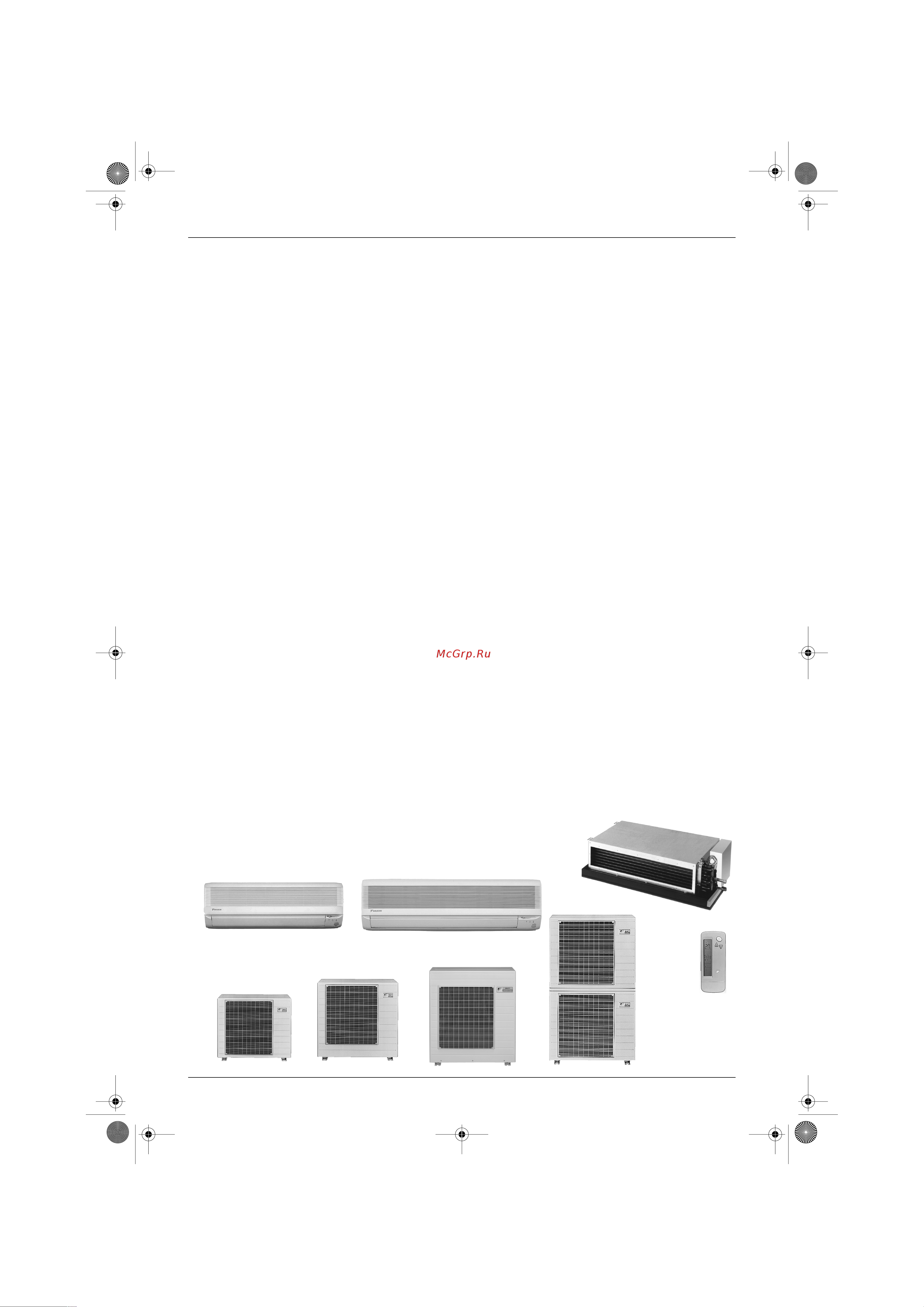
Inverter Multi
MX-H, MK-H Series
.
Heat Pump
Indoor Unit
CDX25HV1NB
CDX35HV1NB
CDX50HV1NB
CDX60HV1NB
FTX25JV1NB
FTX35JV1NB
FTX25HV1NB
FTX35HV1NB
FTX50HV1NB
FTX60HV1NB
Outdoor Unit
2MX52HV1NB
3MX68HV1NB
4MX80HV1NB
.
Cooling Only
Indoor Unit
CDK25HV1NB
CDK35HV1NB
CDK50HV1NB
CDK60HV1NB
FTK25JV1NB
FTK35JV1NB
FTK25HV1NB
FTK35HV1NB
FTK50HV1NB
FTK60HV1NB
Outdoor Unit
4MK90HV1NB
Si-12-001.book Page i Monday, June 25, 2001 1:54 PM
Содержание
- Cooling only indoor unit 1
- Heat pump indoor unit 1
- Inverter multi mx h mk h series 1
- Outdoor unit 1
- And name 5 2
- Caution for diagnosis 05 2
- Control specification 0 2
- Function of main structural parts 4 2
- Introduction vii 2
- List of functions 2
- Main functions 6 2
- Part 1 list of functions 2
- Part 2 specifications 2
- Part 3 printed circuit board connector wiring diagram 2
- Part 4 main functions 5 2
- Part 5 function of main structual parts 3 2
- Part 6 control specification 9 2
- Part 7 system configuration 1 2
- Part 8 service diagnosis 03 2
- Printed circuit board connector wiring diagram and name 6 2
- Specifications 2
- System configuration 2 2
- Check 48 3
- Code indication on the remote control 10 3
- For ftk25j ftk35j ftx25j ftx35j 62 3
- Part 9 removal procedure 61 3
- Problem symptoms and measures 07 3 service check function 08 3
- Troubleshooting 11 3
- Appendix 38 4
- For cdk25 60h series and cdx25 60h series 01 4
- For ftk50 60h series and ftx50 60h series 79 4
- Others 32 4
- Outdoor unit for 2mx52h and 3mx68h 06 4
- Outdoor unit for 4mk90h 4mx80h series 18 4
- Part 10others 31 4
- Part 11appendix 37 4
- Drawings flow charts v 5
- Index i 5
- Introduction 7
- Safety cautions 7
- Warning 7
- Caution 8
- Cautions regarding products after repair 8
- Introduction sie00 04 8
- Warning 8
- Caution 9
- Inspection after repair 9
- Sie00 04 introduction 9
- Warning 9
- Caution 10
- Introduction sie00 04 10
- Using icons 10
- Using icons list 10
- Cooling only model 2 1 heat pump model 3 11
- List of functions 11
- Part 1 list of functions 11
- Cooling only model 12
- List of functions 12
- List of functions sie00 04 12
- Heat pump model 13
- List of functions 3 13
- Sie00 04 list of functions 13
- Part 2 specifications 15
- Specifications 15
- Indoor units cooling only 16
- Specifications 16
- Specifications sie00 04 16
- Wall mounted unit 16
- Concealed ceiling unit 17
- Si 12 001 book page 7 monday june 25 2001 1 54 pm 17
- Sie00 04 specifications 17
- Specifications 7 17
- V 50hz v1nb 17
- Outdoor units cooling only 18
- Si 12 001 book page 8 monday june 25 2001 1 54 pm 18
- Specifications 18
- Specifications sie00 04 18
- V 50hz v1nb 18
- Indoor units heat pump 19
- Sie00 04 specifications 19
- Specifications 9 19
- Wall mounted unit 19
- Concealed ceiling unit 20
- Si 12 001 book page 10 monday june 25 2001 1 54 pm 20
- Specifications 20
- Specifications sie00 04 20
- V 50hz 20
- Outdoor unit heat pump 21
- Si 12 001 book page 11 monday june 25 2001 1 54 pm 21
- Sie00 04 specifications 21
- Specifications 11 21
- V 50hz v1nb 21
- Si 12 001 book page 12 monday june 25 2001 1 54 pm 22
- Specifications 22
- Specifications sie00 04 22
- V 50hz v1nb 22
- Si 12 001 book page 13 monday june 25 2001 1 54 pm 23
- Sie00 04 specifications 23
- Specifications 13 23
- V 50hz v1nb 23
- Part 3 printed circuit board connector wiring diagram and name 25
- Printed circuit board connector wiring diagram and name 6 25
- Cdk25 60h series 26
- Control pcb printed circuit board 1 26
- Cooling only 26
- Heat pump 26
- Name of connector 26
- Other designations 26
- Printed circuit board connector wiring diagram and name 26
- Printed circuit board connector wiring diagram and name sie00 04 26
- Control pcb 1 28
- Ftk25 35j series ftx25 35j series 28
- Name of connector 28
- Printed circuit board connector wiring diagram and name 28
- Printed circuit board connector wiring diagram and name sie00 04 28
- Control pcb printed circuit board 1 30
- Cooling only 30
- Ftk50 60h series 30
- Heat pump 30
- Name of connector 30
- Other designations 30
- Printed circuit board connector wiring diagram and name 30
- Printed circuit board connector wiring diagram and name sie00 04 30
- 2mx52hv1nb 3mx68hv1nb 32
- Name of connector 32
- Other designation 32
- Printed circuit board 1 control pcb printed circuit board 2 monitor pcb 32
- Printed circuit board connector wiring diagram and name 32
- Printed circuit board connector wiring diagram and name sie00 04 32
- 4mx80h 4mk90h series 33
- Cooling only 33
- Heat pump 33
- Name of connector 33
- Other designation 33
- Printed circuit board 1 control and monitor pcb 33
- Printed circuit board connector wiring diagram and name 23 33
- Sie00 04 printed circuit board connector wiring diagram and name 33
- Detail 26 35
- Main functions 6 35
- Part 4 main functions 35
- Detail 36
- Important features of inverters 36
- Inverter power control 36
- Main functions 36
- Main functions sie00 04 36
- Principle of operation of an inverter 36
- Features of the horizontal scroll type compressor 37
- Horizontal scroll type compressor 37
- Main functions 27 37
- Quick heating capability 37
- Sie00 04 main functions 37
- Construction diagram of the scroll compressor 38
- Features and operation of the horizontal scroll type compressor 38
- For ftk ftx50 60 h series only 38
- Main functions 38
- Main functions sie00 04 38
- Power airflow flap diffuser 38
- In cooling operation the diffuser is stored inside the unit and the wide angle flaps send cool air throughout the room 39
- In heating operation warm air is sent out straight down by the flaps while the diffuser produces an air stream that presses down the warm air 39
- Main functions 29 39
- Outside temperature 7ºcdb thermostat setting 23ºc air flow setting high h tap approximately 40 minutes after operation start height of air outlet approx 2 m note that temperature distribution varies depending on the heat insulation furniture arrange and other factors in the room 39
- Sie00 04 main functions 39
- Temperature distribution 39
- Wide angle louvers 40
- Horizontal auto swing up and down 41
- Cooling dry heating operation for heat pump model 42
- Main functions 42
- Main functions sie00 04 42
- Note notes on flap angles the diffuser is kept open in dry cool or fan mode 42
- Note unless swing is selected you should set the flap at a near horizontal angle in cool or dry mode to obtain the best performance 42
- 3 step flow 43
- Although the liquid crystal display of the five step directions of the air flow is common for the modes of cooling dry heating as illustrated above in fact the range of the swing angle is slightly different in every operation mode the position a user set will be selected among the five positions calculated through the preliminary and evenly divided into four partitions which were taken from the upper and lower flap angle s range limits of each mode when auto swing is chosen the flap swings in the swing range which meets the operation mode selected 43
- Fan mode is available for the models of cooling only 43
- For ftk x 25 35j series only outline of the action 43
- For ftx50 60 h series only heat pump only 43
- In the beginning of a heating operation the unit sends warm air towards the wall behind the unit to prevent the air from directly blowing on people in the room after a while it blows air downward to warm up the area close to the floor after the walls and floor become warm the unit sends out air according to the set angle and fan speed air flow angle and fan speed set from remote control 43
- It can be commanded for j type by means of a user setting to select either any one desired position among the five step directions of air flow adjusted on a remote control or auto swing 43
- Main functions 33 43
- Others 43
- Sie00 04 main functions 43
- The vertical louver can be adjusted manually the movable range is 60 degrees for left or right and total 120 degrees a diffuser is not available for j type 43
- Wide angle flaps louvers and auto swing 43
- Automatic air flow control for cooling 45
- Automatic air flow control for heating 45
- Fan speed control for indoor units 45
- For ftk x 25 35j ftk x 50 60 h series control mode 45
- For more information about hall ic refer to hall ic check a6 on page 116 45
- Hh powerful 45
- J type 800 980 rpm during powerful operation 1050 rpm 45
- Ll cooling thermostat off 45
- Lll heating thermostat off h type 500 860 rpm during powerful operation 850 910 rpm 45
- Main functions 35 45
- Note 1 during powerful operation fan operate h tap 50 70 rpm 2 fan stops during defrost operation 45
- Note when there is no operation and the night set mode turns on the step is low refer to night set mode on page 22 45
- Phase control and fan speed control contains 8 steps lll ll l ml m hm h and hh 45
- Phase steps 45
- Sie00 04 main functions 45
- Step cooling heating dry mode 45
- The airflow rate can be automatically controlled depending on the difference between the set temperature and the room temperature this is done through phase control and hall ic control 45
- The following drawing explains the principle for fan speed control for heating 45
- The following drawing explains the principle of fan speed control for cooling 45
- Within this range the airflow rate is automatically controlled when the airflow adjusting button is set to automatic 45
- Air purifying filter 46
- For ftk ftx50 60 h series only 46
- For ftk x 25 35 j ftk x 50 60 h series 46
- In the case of ftk ftx50 60 h series 46
- Main functions 46
- Main functions sie00 04 46
- On off button on indoor unit 46
- Open the front grille 46
- Remove the front grille 46
- Signal receiving sign 46
- Washable grille 46
- Attach the front grille 47
- Clean the front grille 47
- Contents of indication 47
- Filter cleaning indicator 47
- For ftk ftx50 60 h series only 47
- For ftk x 25 35 j ftk x 50 60 h series 47
- Main functions 37 47
- Mold proof air filter 47
- Sie00 04 main functions 47
- For ftk x 25 35 j ftk x 50 60 h series 48
- Hot start function heat pump only 48
- In order to prevent the cold air blast that normally comes when heating is started the temperature of the heat exchanger of the indoor unit is detected and either the air flow is stopped or is made very weak thereby carrying out comfortable heating of the room the cold air blast is also prevented using a similar control when the defrosting operation is started or when the thermostat gets turned on during defrosting or when the thermostat is on in heating mode the indoor heat exchanger temperature 29 c to fan starts to avoid cold draft 48
- In the case of inverter units 48
- Main functions 48
- Main functions sie00 04 48
- Pre heat operation heat pump only 48
- Program dry function 48
- Program dry function removes humidity while preventing the room temperature from lowering since the microcomputer controls both the temperature and air flow volume the temperature adjustment and fan adjustment buttons are inoperable in this mode 48
- The microcomputer automatically sets the temperature and fan settings the difference between the room temperature at startup and the temperature set by the microcomputer is divided into two zones then the unit operates in the dry mode with an appropriate capacity for each zone to maintain the temperature and humidity at a comfortable level 48
- When the equipment has been stopped the compressor is warmed up by passing a small single phasing current through the compressor motor so that the start up is speeded up 2 the power consumption during warming up is about 15 to 35w 3 this function operates only when the outside temperature is low less than about 10ºc so that power saving is achieved 48
- Automatic operation heat pump only 49
- Cooling operation 49
- Detailed explanation of the function 49
- Main functions 39 49
- Night set mode 49
- Sie00 04 main functions 49
- The night set circuit 49
- With compressor capacity supplied with no compressor capacity supplied 49
- Auto restart function 50
- For ftk x 25 35 j series only outline 50
- Heating operation 50
- Intelligent eye 50
- Main functions 50
- Main functions sie00 04 50
- Processing 50
- Self diagnosis digital display 50
- Self diagnosis led display 50
- Main functions 41 51
- Others 51
- Sie00 04 main functions 51
- Since the set temperature is shifted by 2 c higher for 40 minutes compressor speed becomes low and can realize energy saving operation but as thermostat is prone to be off by the fact that the set temperature has been shifted the thermostat off action is prohibited in 40 minutes so as to prevent this phenomena after this 40 minutes the prohibition of the thermostat off is cancelled and it can realize the conditions to conduct thermostat off depending on the room temperature in or after this forty minutes if the sensor detects human motion detection signal it turns on human detection led and let the set temperature and the fan speed return to the original set point keeping a normal operation 51
- The dry operation can t command the setting temperature with a remote control but internally the set temperature is shifted by 1 c 51
- The motions for example in cooling 51
- When a micro computer doesn t have a signal from the sensor in 20 minutes it judges that no body is in the room and turns off the human detection led operating the unit in temperature sifted 2 c from the set temperature cooling 2 c higher dry 1 c higher and auto according to the operation mode at that time 1 in case of fan mode the fan speed reduces by 50 rpm 51
- For ftk x 25 35 j series only outline 52
- Good sleep cooling control 52
- Main functions 52
- Main functions sie00 04 52
- Notes 1 each timer s counting stop is not related to a thermostat on off 2 when the sleeping control works by the off timer the shift from the set temperature should be just 1 c with this control function the temperature shift of the normal off timer will not be carried out however the passed time should be remembered since the off timer was set 3 while operation with the good sleep cooling control and off timer setting if the signal of the good sleep cooling off signal comes the level of the set temperature shift should be set corresponding to the same with an existing value in accordance with the passed time since the off timer was set 4 when the good sleep cooling control is on while a normal operation with a off timer is going on once returning to the original criterion which doesn t shift the timer s set temperature and the shift alteration at every sequence by 1 c is carried out in accordance with the value above mentioned 5 fan speed will change by the alteration of the set temp 52
- Processing 52
- The function to create deep sleeping and to offer good sleep by altering the set tempeatures in certain intervals to give temperature variation to a living space based on 1 f temperature fluctuation principle in case of going to bed while air conditioner keeps operating in cooling mode 52
- Function of main structural parts 4 53
- Part 5 function of main structual parts 53
- Cooling only model 54
- Function of main structual parts 54
- Function of main structural parts 54
- Function of main structural parts sie00 04 54
- Heat pump model 54
- Main structural parts 54
- Scroll compressor structural drawing 54
- A outdoor heat exchanger thermistor dcb 55
- B discharge pipe thermistor dot 55
- C gas pipe thermistor dgn 55
- Function of main structual parts 45 55
- Function of thermistor 55
- Heat pump model 55
- Sie00 04 function of main structural parts 55
- D indoor heat exchanger thermistor dcn 56
- E indoor liquid pipe thermistor dln 56
- Function of main structual parts 56
- Function of main structural parts sie00 04 56
- A outdoor heat exchanger thermistor dcb 57
- B discharge pipe thermistor dot 57
- C gas pipe thermistor dgn 57
- Cooling only model 57
- D indoor heat exchanger thermistor dcn 57
- Function of main structual parts 47 57
- Sie00 04 function of main structural parts 57
- Control specification 0 59
- Part 6 control specification 59
- Control specification 60
- Control specification sie00 04 60
- Detail 60
- Details of functions 60
- Mode component 60
- Outline 60
- Control specification 51 61
- Detail 61
- Frequency control 61
- Outline 61
- Sie00 04 control specification 61
- Control specification 62
- Control specification sie00 04 62
- Detail 62
- Outline 62
- Preheating operation 62
- 3 minutes stand by 63
- Compressor protection function 63
- Control specification 53 63
- Detail 63
- Discharge pipe control 63
- Four way valve operation compensation only for heat pump model 63
- Four way valve switching only for heat pump model 63
- Outline 63
- Sie00 04 control specification 63
- Control specification 64
- Control specification sie00 04 64
- Control to prevent freezing during cooling operation 64
- Detail 64
- Input current control 64
- Outline 64
- Control specification 55 65
- Detail 65
- Fan control 65
- Heating peak cut control only for heat pump model 65
- Outline 65
- Sie00 04 control specification 65
- Control specification 66
- Control specification sie00 04 66
- Defrost control only for heat pump model 66
- Detail 66
- Moisture protection function 1 66
- Moisture protection function 2 66
- Outline 66
- Control specification 57 67
- Detail 67
- Low hz high pressure limit only for heat pump model 67
- Outline 67
- Sie00 04 control specification 67
- Control specification 68
- Control specification sie00 04 68
- Electronic expansion valve control 68
- Outline 68
- Control specification 59 69
- Detail 69
- Sie00 04 control specification 69
- The followings are the examples of control which function in each mode by the motorized valve control 69
- Control specification 70
- Control specification sie00 04 70
- Control when discharge pipe temperature is abnormally high 70
- Control when starting changing operating room 70
- Detail 70
- Electronic expansion valve is fully closed pressure equalization control 70
- Electronic expansion valve is fully closed when power is turned on 70
- Gas pipe isothermal control during cooling 70
- Heat exchanger isothermal control for heating only for heat pump model 70
- Oil recovery function 70
- Opening limit of electronic expansion valve 70
- Outline 70
- Control specification 61 71
- Control when frequency is changed 71
- Control when the discharge pipe thermistor is disconnected 71
- Detail 71
- Outline 71
- Sc control only for heat pump model 71
- Sie00 04 control specification 71
- Target discharge pipe temperature control 71
- Control specification 72
- Control specification sie00 04 72
- Detail 72
- Detection of over load and over current 72
- Gas insufficient zone 72
- Insufficient gas control 72
- Outline 72
- Sensor malfunction detection 72
- Control specification 63 73
- Detail 73
- Detection of optimum v f lock 73
- Detection of scr scroll compressor starting malfunction 73
- Forced operation mode only for heat pump model 73
- Outline 73
- Preventing indoor freezing 73
- Sie00 04 control specification 73
- Checking incorrect wiring 74
- Control specification 74
- Control specification sie00 04 74
- Detail 74
- Forced cooling forced heating only for heat pump model 74
- Outline 74
- When the wiring error check function is activated the microcomputer automatically locates and corrects wiring errors if any this function is especially useful when connection wires cannot be checked easily because of buried pipes to activate the check function press the wiring error check switch located on the right panel of the outdoor unit pressing the switch enables normal air conditioner operation even if the wires are incorrectly connected between room a and room b outline of function when the electronic expansion valve is opened during cooling operation the temperature of the heat exchanger connected may drop utilize this phenomena to open the electronic expansion valve one after the other from the a port and carry out each judgment 1 allowable conditions 1 the indoor units in all rooms are not abnormal and not in the freezing prohibiting zone or peak cut prohibiting zone 1 the outdoor unit is not abnormal 1 not in a 3 minute stand by 1 the outdoor unit operating mode is in the s 74
- Control specification 65 75
- Sie00 04 control specification 75
- Control specification 76
- Control specification sie00 04 76
- The above led operations indicate the following connections automatic correction pipe a port connected to wiring room b pipe b port connected to wiring room a 76
- When leds flash as shown below 76
- Control specification 67 77
- Detail 77
- Jis function 77
- Outline 77
- Sie00 04 control specification 77
- Additional function 78
- Connection pipe condensation preventing function 78
- Control specification 78
- Control specification sie00 04 78
- Powerful operation mode 78
- Priority room setting 4mx80h 4mk90h only 78
- Voltage detection function 4mx80h 4mk90h only 78
- Control specification 69 79
- Fixed cooling heating mode 4mx80h only 79
- Sie00 04 control specification 79
- Operation instructions 72 81
- Part 7 system configuration 81
- System configuration 2 81
- Operation instructions 82
- System configuration 82
- System configuration sie00 04 82
- Air inlet 83
- Air outlet louvre vertical blades 83
- Air purifying filter front grille 83
- Caution 83
- Flap horizontal blade 83
- Ftk25 35 j ftx25 35 j 83
- Grille tab 83
- Indoor unit 83
- Intelligent eye lamp green operation lamp green 83
- On off button 83
- Opening the front grille 83
- Si 12 001 book page 73 monday june 25 2001 1 54 pm 83
- Timer lamp orange 83
- Open the cover 84
- Outdoor unit 84
- Remote control 84
- Sensor 84
- Si 12 001 book page 74 monday june 25 2001 1 54 pm 84
- System configuration 84
- System configuration sie00 04 84
- About batteries 85
- About the remote control 85
- Attention 85
- Operating the remote control 85
- Position and correctly 85
- Receiver 85
- Remote control 85
- Remote control holder set 85
- Setting the batteries 85
- Si 12 001 book page 75 monday june 25 2001 1 54 pm 85
- To fix the remote control holder on the wall 85
- Blinks 86
- Indoor unit 86
- Is displayed 86
- N setting the air purifying filters 86
- N setting the clock 86
- N turn the breaker on 86
- Open the front grille 86
- Please note 86
- Pull out the air filters 86
- Set the air filters in their original positions and close the front grille 86
- Set the air purifying filters 86
- Si 12 001 book page 76 monday june 25 2001 1 54 pm 86
- Tips for saving energy 86
- To set the clock to the present 86
- N to change the air flow direction 87
- N to stop 87
- On off 87
- Si 12 001 book page 77 monday june 25 2001 1 54 pm 87
- Then operation lamp goes off 87
- N to cancel powerful operation 88
- Notes on powerful operation 88
- Powerful operation 88
- System configuration 88
- System configuration sie00 04 88
- Adjusting the air flow direction 89
- Adjusting the horizontal blade flap 89
- Adjusting the louvre 89
- Attention 89
- Notes on flap angles 89
- Sie00 04 system configuration 89
- System configuration 79 89
- You can adjust the air flow direction to increase your comfort 89
- Attention 90
- Combining on timer and off timer 90
- Example 90
- Is operating 90
- Notes on off timer 90
- Notes on on off timer 90
- Off timer operation 90
- On off 90
- On timer operation 90
- Once again 90
- Reaches the point you like 90
- Si 12 001 book page 80 monday june 25 2001 1 54 pm 90
- Then the timer lamp goes off 90
- Then the timer lamp lights up 90
- Timer functions are useful for automatically switching the air conditioner on or off at night or in the morning you can also use off timer and on timer in combination 90
- To cancel the timer 90
- Until the time setting 90
- While the air conditioner 90
- While the air conditioner is not operating 90
- N to cancel the good sleep cooling operation press 91
- N to change the air flow direction setting 91
- N to change the air flow rate setting 91
- N to change the temperature setting 91
- Notes on good sleep cooling operation 91
- What is 1 f fluctuation 91
- Caution 92
- Gy saving 92
- Intelligent eye is useful for 92
- Notes on intelligent eye 92
- Air filter air purifying filter frame 93
- Caution 93
- Cleaning the air filters 93
- Cleaning the indoor and outdoor units and the remote control 93
- Hold the recessed parts of the frame and unhook the four claws 93
- Replacing air purifying filters 93
- Before a long idle period 94
- Caution 94
- Cleaning the front grille 94
- Ftk50 60h ftx50 60h series 95
- Cdk25 60h cdx25 60h series 105
- Caution for diagnosis 05 113
- Code indication on the remote control 10 113
- Part 8 service diagnosis 113
- Problem symptoms and measures 07 3 service check function 08 113
- Troubleshooting 11 113
- Check 48 114
- How to check 148 114
- Caution for diagnosis 115
- Indicator lamps 115
- Location of operation lamp 115
- Service diagnosis 105 115
- Sie00 04 caution for diagnosis 115
- Troubleshooting with the operation lamp 115
- Caution for diagnosis sie00 04 116
- Service diagnosis 116
- Troubleshooting with the led indication 116
- Problem symptoms and measures 117
- Service diagnosis 107 117
- Sie00 04 problem symptoms and measures 117
- Arc423 series ftk x 25 35j series 118
- In the arc423a series the temperature display sections on the main unit indicate corresponding codes 1 when the timer cancel button is held down for 5 seconds a 00 indication flashes on the temperature display section 118
- Note 1 a short beep and two consecutive beeps indicate non corresponding codes 2 to cancel the code display hold the timer cancel button down for 5 seconds the code display also cancels itself if the button is not pressed for 1 minute 118
- Press the timer cancel button repeatedly until a continuous beep is produced the code indication changes in the sequence shown below and notifies with along beep 118
- Service check function 118
- Service check function sie00 04 118
- Service diagnosis 118
- Arc417 series ftk x 50 60h series 119
- In the arc417a series the temperature display sections on the main unit indicate corresponding codes 1 when the timer cancel button is held down for 5 seconds a 00 indication flashes on the temperature display section 119
- Note 1 a short beep and two consecutive beeps indicate non corresponding codes 2 to cancel the code display hold the timer cancel button down for 5 seconds the code display also cancels itself if the button is not pressed for 1 minute 119
- Press the timer cancel button repeatedly until a continuous beep is produced the code indication changes in the sequence shown below and notifies with along beep 119
- Service diagnosis 109 119
- Sie00 04 service check function 119
- Code indication on the remote control 120
- Code indication on the remote control sie00 04 120
- Error codes and description of fault 120
- Service diagnosis 120
- 5 5 5 a5 121
- 5 5 5 a6 121
- 5 5 5 c 121
- 5 5 5 c9 121
- Ftk x 25 35 j series 121
- Ftk x 50 60h cdk x 25 60h series 121
- Indoor units 121
- Service diagnosis 111 121
- Sie00 04 troubleshooting 121
- Troubleshooting 121
- Outdoor units 122
- Faulty pcb 123
- Indoor unit led display 124
- Malfunction decision conditions 124
- Method of malfunction detection 124
- Operation halt due to the freeze protection function 124
- Remote control display 124
- Service diagnosis 124
- Supposed causes 124
- Troubleshooting 124
- Troubleshooting sie00 04 124
- Indoor unit led display 125
- Malfunction decision conditions 125
- Method of malfunction detection 125
- Operation halt due to fan motor ac motor or related abnormality 125
- Remote control display 125
- Service diagnosis 115 125
- Sie00 04 troubleshooting 125
- Supposed causes 125
- Troubleshooting 125
- C4 c5 c9 ca 126
- Indoor unit led display 126
- Malfunction decision conditions 126
- Method of malfunction detection 126
- Operation halt due to detection of thermistor or related abnormality 126
- Remote control display 126
- Service diagnosis 126
- Supposed causes 126
- Troubleshooting 126
- Troubleshooting sie00 04 126
- Faulty indoor unit pcb 127
- Indoor unit led display 127
- Malfunction decision conditions 127
- Method of malfunction detection 127
- Remote control display 127
- Service diagnosis 117 127
- Sie00 04 troubleshooting 127
- Supposed causes 127
- Troubleshooting 127
- Faulty indoor unit pcb 128
- Display disabled by fault power supply faulty signal transmitting receiving circuit in indoor printed circuit boards 1 and 2 microcomputer program is in abnormal condition due to an external factor noise momentary voltage drop momentary power failure etc faulty indoor unit pcbs 1 and 2 129
- Faulty power supply or indoor unit pcb for ftk x 25 35j 129
- Indoor unit led display 129
- Malfunction decision conditions 129
- Method of malfunction detection 129
- Remote control display 129
- Service diagnosis 119 129
- Sie00 04 troubleshooting 129
- Supposed causes 129
- The proper program operation of the microcomputer is checked by the program 2 in indoor outdoor signal communications the indoor unit determines whether the outdoor unit receives signals properly by detecting signals transmitted by the outdoor unit to the indoor unit 129
- Troubleshooting 129
- When the microcomputer program does not function properly 2 when the indoor unit determines that the indoor unit does not properly receive signals transmitted by the outdoor unit in indoor outdoor signal communications 129
- Faulty power supply or indoor unit pcb for ftk x 50 60h cdk x 25 60h 130
- Indoor unit led display 130
- Malfunction decision conditions 130
- Method of malfunction detection 130
- Remote control display 130
- Service diagnosis 130
- Supposed causes 130
- Troubleshooting 130
- Troubleshooting sie00 04 130
- Check no 7 refer to p 58 131
- Service diagnosis 121 131
- Sie00 04 troubleshooting 131
- Troubleshooting 131
- Indoor unit led display 132
- Malfunction decision conditions 132
- Method of malfunction detection 132
- Remote control display 132
- Service diagnosis 132
- Signal transmission error between indoor and outdoor units 132
- Supposed causes 132
- Troubleshooting 132
- Troubleshooting sie00 04 132
- Indoor unit led display 133
- Malfunction decision conditions 133
- Method of malfunction detection 133
- Remote control display 133
- Service diagnosis 123 133
- Sie00 04 troubleshooting 133
- Signal transmission error between indoor unit and remote control 133
- Supposed causes 133
- Troubleshooting 133
- Malfunction decision conditions 134
- Method of malfunction detection 134
- Operation halt due to detection of insufficient gas 134
- Outdoor unit led display 134
- Remote control display 134
- Service diagnosis 134
- Supposed causes 134
- Troubleshooting sie00 04 134
- Check no refer to p 48 135
- Check no refer to p 49 135
- Ct check refer to p 34 135
- Service diagnosis 125 135
- Sie00 04 troubleshooting 135
- Troubleshooting 135
- Malfunction decision conditions 136
- Method of malfunction detection 136
- Operation halt due to it activation 136
- Outdoor unit led display 136
- Remote control display 136
- Service diagnosis 136
- Supposed causes 136
- Troubleshooting 136
- Troubleshooting sie00 04 136
- Discharge pipe temperature error 137
- Malfunction decision conditions 137
- Method of malfunction detection 137
- Outdoor unit led display 137
- Remote control display 137
- Service diagnosis 127 137
- Sie00 04 troubleshooting 137
- Supposed causes 137
- Troubleshooting 137
- Malfunction decision conditions 138
- Method of malfunction detection 138
- Operation halt due to compressor startup error 138
- Outdoor unit led display 138
- Remote control display 138
- Service diagnosis 138
- Supposed causes 138
- Troubleshooting sie00 04 138
- Check no refer to p 49 139
- Check no refer to p 50 139
- Check no refer to p 51 139
- Is it normal 139
- Service diagnosis 129 139
- Sie00 04 troubleshooting 139
- Troubleshooting 139
- Malfunction decision conditions 140
- Method of malfunction detection 140
- Operation halt due to discharge pipe temperature rise 140
- Outdoor unit led display 140
- Remote control display 140
- Service diagnosis 140
- Supposed causes 140
- Troubleshooting 140
- Troubleshooting sie00 04 140
- And 90 series 150 c 130 c 141
- Fin temperature rise due to faulty outdoor unit fan fin temperature rise due to short circuit detection error due to faulty outdoor unit pcb 141
- Malfunction decision conditions 141
- Method of malfunction detection 141
- Model operation halt temperature reset temperature 141
- Operation halt due to radiation fin temperature rise protection of driver overheat 141
- Outdoor unit led display 141
- Radiation fin temperature rise is detected using the temperature of the radiation fins detected by the fin thermistor during compressor operation 141
- Remote control display 141
- Service diagnosis 131 141
- Sie00 04 troubleshooting 141
- Supposed causes 141
- Troubleshooting 141
- When the radiation fin temperature is as below mentioned value during compressor operation judgment temperature 141
- Malfunction decision conditions 142
- Method of malfunction detection 142
- Operation halt due to detection of ct error for 2mx52h 3mx68h series 142
- Outdoor unit led display 142
- Remote control display 142
- Service diagnosis 142
- Supposed causes 142
- Troubleshooting 142
- Troubleshooting sie00 04 142
- Check no 0 refer to p 55 143
- Check no 1 refer to p 56 143
- Check no refer to p 48 143
- Check no refer to p 50 143
- Service diagnosis 133 143
- Sie00 04 troubleshooting 143
- Troubleshooting 143
- Malfunction decision conditions 144
- Method of malfunction detection 144
- Operation halt due to detection of ct error for 4mk90h 4mx80h series 144
- Outdoor unit led display 144
- Remote control display 144
- Service diagnosis 144
- Supposed causes 144
- Troubleshooting 144
- Troubleshooting sie00 04 144
- Malfunction decision conditions 145
- Method of malfunction detection 145
- Operation halt due to thermistor error or disconnection detection 145
- Outdoor unit led display 145
- Remote control display 145
- Service diagnosis 135 145
- Sie00 04 troubleshooting 145
- Supposed causes 145
- Troubleshooting 145
- Malfunction decision conditions 146
- Method of malfunction detection 146
- Operation halt due to thermistor error 146
- Outdoor unit led display 146
- Remote control display 146
- Service diagnosis 146
- Supposed causes 146
- Troubleshooting 146
- Troubleshooting sie00 04 146
- Malfunction decision conditions 147
- Method of malfunction detection 147
- Operation halt due to gas pipe thermistor error 147
- Outdoor unit led display 147
- Remote control display 147
- Service diagnosis 137 147
- Sie00 04 troubleshooting 147
- Supposed causes 147
- Troubleshooting 147
- Malfunction decision conditions 148
- Method of malfunction detection 148
- Operation halt due to detection of output over current 148
- Outdoor unit led display 148
- Remote control display 148
- Service diagnosis 148
- Supposed causes 148
- Troubleshooting sie00 04 148
- 1 indication of output over current detection of compressor startup and detection of compressor startup error 149
- Internal wiring errors can cause an output over current if the equipment stops due to an output over current after the wires are disconnected and connected again for parts replacement etc check for wiring errors 149
- Service diagnosis 139 149
- Sie00 04 troubleshooting 149
- Troubleshooting 149
- Malfunction decision conditions 150
- Method of malfunction detection 150
- Operation halt due to detection of input over current 150
- Outdoor unit led display 150
- Remote control display 150
- Service diagnosis 150
- Supposed causes 150
- Troubleshooting sie00 04 150
- Check no 2 refer to p 56 151
- Check no refer to p 48 151
- Check no refer to p 50 151
- Check no refer to p 51 151
- Check no refer to p 53 151
- Internal wiring errors can cause an input over current if the equipment stops due to an input over current after the wires are disconnected and connected again for parts replacement etc check for wiring errors 151
- Service diagnosis 141 151
- Sie00 04 troubleshooting 151
- Troubleshooting 151
- Malfunction decision conditions 152
- Method of malfunction detection 152
- Operation halt due to peak cut only for heat pump model or freeze protection control 152
- Outdoor unit led display 152
- Remote control display 152
- Service diagnosis 152
- Supposed causes 152
- Troubleshooting sie00 04 152
- Check no refer to p 48 153
- Check no refer to p 49 153
- Service diagnosis 143 153
- Sie00 04 troubleshooting 153
- Troubleshooting 153
- Malfunction decision conditions 154
- Method of malfunction detection 154
- Operation halt due to the deicing function 154
- Outdoor unit led display 154
- Remote control display 154
- Service diagnosis 154
- Supposed causes 154
- Troubleshooting 154
- Troubleshooting sie00 04 154
- Faulty outdoor unit pcb and transmitting receiving circuit 155
- Malfunction decision conditions 155
- Method of malfunction detection 155
- Outdoor unit led display 155
- Remote control display 155
- Service diagnosis 145 155
- Sie00 04 troubleshooting 155
- Supposed causes 155
- Troubleshooting 155
- Check no 3 refer to p 57 156
- Check no refer to p 48 156
- Service diagnosis 156
- Troubleshooting 156
- Troubleshooting sie00 04 156
- Faulty outdoor unit pcb 157
- Malfunction decision conditions 157
- Method of malfunction detection 157
- Outdoor unit led display 157
- Remote control display 157
- Service diagnosis 147 157
- Sie00 04 troubleshooting 157
- Supposed causes 157
- Troubleshooting 157
- How to check 158
- Wiring error check 158
- Check no 159
- Conduct the followings to check the electronic expansion valve ev 1 check to see if the ev connector is correctly inserted in the pcb compare the ev unit and the connector number 2 turn the power off and back on again and check to see if all the evs generate latching sound 3 if any of the evs does not generate latching noise in the above step 2 disconnect that connector and check the conductivity using a tester check the conductivity between pins 1 3 and 6 and between pins 2 4 and 5 if there is no conductivity between the pins the ev coil is faulty 4 if no ev generates latching sound in the above step 2 the outdoor unit pcb is faulty 5 if the conductivity is confirmed in the above step 2 mount a good coil which generated latching sound in the ev unit that did not generate latching sound and check to see if that ev generates latching sound if latching sound is generated the outdoor unit pcb is faulty if latching sound is not generated the ev unit is faulty 159
- Electronic expansion valve check 159
- Note please note that the latching sound varies depending on the valve type 159
- Service diagnosis 149 159
- Sie00 04 check 159
- Check no 160
- Check sie00 04 160
- For model with single phase 230 vac specification 160
- Negati 160
- Power transistor check 160
- Service diagnosis 160
- Check no 161
- Output current measurement 161
- Output voltage measurement 161
- Power transistor output check 161
- Service diagnosis 151 161
- Sie00 04 check 161
- Check no 162
- Check sie00 04 162
- Remove the connectors of the thermistors on the pcb and measure the resistance of each thermistor using tester the relationship between normal temperature and resistance is shown in the graph and the table below 162
- Service diagnosis 162
- Thermistor resistance check 162
- Check no 163
- Installation condition check 163
- Service diagnosis 153 163
- Sie00 04 check 163
- Check no 164
- Check sie00 04 164
- Internal wiring check 1 164
- Inverter units input current measurement 164
- Service diagnosis 164
- Check no 165
- Check no 0 165
- Internal wiring check 2 165
- Mrm11 12 and mrm20 check 165
- Service diagnosis 155 165
- Sie00 04 check 165
- 0 0 or 166
- Check no 1 166
- Check no 2 166
- Check sie00 04 166
- Discharge pressure check 166
- For digital tester 166
- Negative 166
- Normal resistance several 166
- Positive 166
- Rectifier check 166
- Service diagnosis 166
- Several 166
- Terminal of tester negative terminal 166
- Terminal of tester positive terminal 166
- There are several different terminal position patterns therefore be sure to check the terminal marks 166
- Unacceptable resistance 0 o 166
- Check no 3 167
- Check no 4 167
- Check no 5 167
- Fig fig 167
- Inverter units compressor refrigerant system check 167
- Inverter units refrigerant system check 167
- Measure the power supply waveform between pins 1 and 3 on the terminal board and check the waveform disturbance check to see if the power supply waveform is a sine wave fig check to see if there is waveform disturbance near the zero cross sections circled in fig 167
- Power supply waveforms check 167
- Service diagnosis 157 167
- Sie00 04 check 167
- Check no 6 168
- Check no 7 168
- Check sie00 04 168
- Inverter units hall ic check 168
- Inverter units indoor unit pcb 2 output voltage check 168
- Service diagnosis 168
- Check no 8 169
- Check no 9 169
- Internal wiring check 1 169
- Inverter units input current measurement 169
- Service diagnosis 159 169
- Sie00 04 check 169
- For cdk25 60h series and cdx25 60h series 01 171
- For ftk25j ftk35j ftx25j ftx35j 62 171
- For ftk50 60h series and ftx50 60h series 79 171
- Outdoor unit for 2mx52h and 3mx68h 06 171
- Outdoor unit for 4mk90h 4mx80h series 18 171
- Part 9 removal procedure 171
- For ftk25j ftk35j ftx25j ftx35j 172
- For ftk25j ftk35j ftx25j ftx35j sie00 04 172
- Procedure 172
- Removal of air filter 172
- Removal procedure 172
- Removal procedure 163 173
- Sie00 04 for ftk25j ftk35j ftx25j ftx35j 173
- For ftk25j ftk35j ftx25j ftx35j sie00 04 174
- Procedure 174
- Removal of front grille 174
- Removal procedure 174
- Removal procedure 165 175
- Sie00 04 for ftk25j ftk35j ftx25j ftx35j 175
- For ftk25j ftk35j ftx25j ftx35j sie00 04 176
- Procedure 176
- Removal of horizontal blade and vertical blade 176
- Removal procedure 176
- Removal procedure 167 177
- Sie00 04 for ftk25j ftk35j ftx25j ftx35j 177
- For ftk25j ftk35j ftx25j ftx35j sie00 04 178
- Procedure 178
- Removal of switch box pc board and swing motor 178
- Removal procedure 178
- Removal procedure 169 179
- Sie00 04 for ftk25j ftk35j ftx25j ftx35j 179
- For ftk25j ftk35j ftx25j ftx35j sie00 04 180
- Removal procedure 180
- Disengage the four knobs on the back of the display printed circuit board 181
- Display printed circuit board 181
- Removal procedure 171 181
- Sie00 04 for ftk25j ftk35j ftx25j ftx35j 181
- For ftk25j ftk35j ftx25j ftx35j sie00 04 182
- Removal procedure 182
- Procedure 183
- Removal of heat exchanger 183
- Removal procedure 173 183
- Sie00 04 for ftk25j ftk35j ftx25j ftx35j 183
- For ftk25j ftk35j ftx25j ftx35j sie00 04 184
- Removal procedure 184
- Install of drain plug 185
- Procedure 185
- Removal procedure 175 185
- Sie00 04 for ftk25j ftk35j ftx25j ftx35j 185
- For ftk25j ftk35j ftx25j ftx35j sie00 04 186
- Procedure 186
- Removal of fan rotor and motor 186
- Removal procedure 186
- Loosen the hexagon head set screw on the fan rotor 187
- Removal procedure 177 187
- Remove a screw on the left side panel 187
- Remove the motor and fan rotor 187
- Sie00 04 for ftk25j ftk35j ftx25j ftx35j 187
- For ftk25j ftk35j ftx25j ftx35j sie00 04 188
- Removal procedure 188
- For ftk50 60h series and ftx50 60h series 189
- Procedure 189
- Removal of air filter 189
- Removal procedure 179 189
- Sie00 04 for ftk50 60h series and ftx50 60h series 189
- For ftk50 60h series and ftx50 60h series sie00 04 190
- Removal procedure 190
- Procedure 191
- Removal of front grille 191
- Removal procedure 181 191
- Sie00 04 for ftk50 60h series and ftx50 60h series 191
- For ftk50 60h series and ftx50 60h series sie00 04 192
- Opening and closing of service cover changing settings at installation site 192
- Procedure 192
- Removal procedure 192
- Procedure 193
- Removal of front panel 193
- Removal procedure 183 193
- Sie00 04 for ftk50 60h series and ftx50 60h series 193
- For ftk50 60h series and ftx50 60h series sie00 04 194
- Removal procedure 194
- Procedure 195
- Removal of horizontal and vertical blades 195
- Removal procedure 185 195
- Sie00 04 for ftk50 60h series and ftx50 60h series 195
- For ftk50 60h series and ftx50 60h series sie00 04 196
- Removal procedure 196
- Procedure 197
- Removal of drain pan 197
- Removal procedure 187 197
- Sie00 04 for ftk50 60h series and ftx50 60h series 197
- For ftk50 60h series and ftx50 60h series sie00 04 198
- Removal procedure 198
- Procedure 199
- Removal of pc board 199
- Removal procedure 189 199
- Sie00 04 for ftk50 60h series and ftx50 60h series 199
- For ftk50 60h series and ftx50 60h series sie00 04 200
- Removal procedure 200
- Removal procedure 191 201
- Sie00 04 for ftk50 60h series and ftx50 60h series 201
- For ftk50 60h series and ftx50 60h series sie00 04 202
- Procedure 202
- Removal of electrical parts box 202
- Removal procedure 202
- Removal procedure 193 203
- Sie00 04 for ftk50 60h series and ftx50 60h series 203
- For ftk50 60h series and ftx50 60h series sie00 04 204
- Procedure 204
- Removal of swing motor assembly 204
- Removal procedure 204
- Piping of drain hose at left side 205
- Procedure 205
- Removal procedure 195 205
- Sie00 04 for ftk50 60h series and ftx50 60h series 205
- For ftk50 60h series and ftx50 60h series sie00 04 206
- Procedure 206
- Removal of heat exchanger 206
- Removal procedure 206
- Removal procedure 197 207
- Sie00 04 for ftk50 60h series and ftx50 60h series 207
- For ftk50 60h series and ftx50 60h series sie00 04 208
- Removal procedure 208
- Removal procedure 199 209
- Sie00 04 for ftk50 60h series and ftx50 60h series 209
- For ftk50 60h series and ftx50 60h series sie00 04 210
- Procedure 210
- Removal of fan rotor and motor 210
- Removal procedure 210
- External appearance and removal of electrical box cover 211
- For cdk25 60h series and cdx25 60h series 211
- Procedure 211
- Removal procedure 201 211
- Sie00 04 for cdk25 60h series and cdx25 60h series 211
- For cdk25 60h series and cdx25 60h series sie00 04 212
- Procedure 212
- Removal of pcb and heat exchanger thermistor 212
- Removal procedure 212
- Procedure 213
- Removal of drain pan and fan motor 213
- Removal procedure 203 213
- Sie00 04 for cdk25 60h series and cdx25 60h series 213
- For cdk25 60h series and cdx25 60h series sie00 04 214
- Procedure 214
- Removal of fan rotor and motor 214
- Removal procedure 214
- Removal procedure 205 215
- Sie00 04 for cdk25 60h series and cdx25 60h series 215
- Outdoor unit for 2mx52h and 3mx68h 216
- Outdoor unit for 2mx52h and 3mx68h sie00 04 216
- Procedure 216
- Removal of the exterior panels 216
- Removal procedure 216
- Procedure 217
- Removal of the propeller fan and motor 217
- Removal procedure 207 217
- Sie00 04 outdoor unit for 2mx52h and 3mx68h 217
- Outdoor unit for 2mx52h and 3mx68h sie00 04 218
- Removal procedure 218
- Procedure 219
- Removal of the electrical box 219
- Removal procedure 209 219
- Sie00 04 outdoor unit for 2mx52h and 3mx68h 219
- Outdoor unit for 2mx52h and 3mx68h sie00 04 220
- Removal procedure 220
- Removal procedure 211 221
- Sie00 04 outdoor unit for 2mx52h and 3mx68h 221
- Outdoor unit for 2mx52h and 3mx68h sie00 04 222
- Procedure 222
- Removal of the pcb 222
- Removal procedure 222
- Removal of the compressor 223
- Outdoor unit for 2mx52h and 3mx68h sie00 04 224
- Removal procedure 224
- Removal procedure 215 225
- Sie00 04 outdoor unit for 2mx52h and 3mx68h 225
- Outdoor unit for 2mx52h and 3mx68h sie00 04 226
- Procedure 226
- Removal of the electronic expansion valve 226
- Removal procedure 226
- Procedure 227
- Removal of 4 way valve heat pump model only 227
- Removal procedure 217 227
- Sie00 04 outdoor unit for 2mx52h and 3mx68h 227
- Outdoor unit for 4mk90h 4mx80h series 228
- Outdoor unit for 4mk90h 4mx80h series sie00 04 228
- Procedure 228
- Removal of outer panels 228
- Removal procedure 228
- Removal procedure 219 229
- Sie00 04 outdoor unit for 4mk90h 4mx80h series 229
- Outdoor unit for 4mk90h 4mx80h series sie00 04 230
- Procedure 230
- Removal of propeller fan motor 230
- Removal procedure 230
- Procedure 231
- Removal of pcb 231
- Removal procedure 221 231
- Sie00 04 outdoor unit for 4mk90h 4mx80h series 231
- Outdoor unit for 4mk90h 4mx80h series sie00 04 232
- Removal procedure 232
- Procedure 233
- Removal of 4 way valve 233
- Removal procedure 223 233
- Sie00 04 outdoor unit for 4mk90h 4mx80h series 233
- Outdoor unit for 4mk90h 4mx80h series sie00 04 234
- Removal procedure 234
- Removal procedure 225 235
- Sie00 04 outdoor unit for 4mk90h 4mx80h series 235
- Outdoor unit for 4mk90h 4mx80h series sie00 04 236
- Procedure 236
- Removal of solenoid valve and motorized valve 236
- Removal procedure 236
- Procedure 237
- Removal of electrical parts box 237
- Removal procedure 227 237
- Sie00 04 outdoor unit for 4mk90h 4mx80h series 237
- Outdoor unit for 4mk90h 4mx80h series sie00 04 238
- Procedure 238
- Removal of noise insulation for compressor 238
- Removal procedure 238
- Procedure 239
- Removal of compressor 239
- Removal procedure 229 239
- Sie00 04 outdoor unit for 4mk90h 4mx80h series 239
- Outdoor unit for 4mk90h 4mx80h series sie00 04 240
- Removal procedure 240
- Others 32 241
- Part 10 others 241
- Explanation for ftk x 25 35j series 242
- For cooling operation in case of low ambient temperature 242
- For heat pump 242
- Others 242
- Others sie00 04 242
- Test run from the remote control for heat pump model only 242
- Centralized control for krc72 krp413a1s 243
- Cut jumper jc on the indoor pc bord 243
- Dry keep change over switch all indoor models for cooling only and heat pump model 243
- Method of operating air conditioners individually when two units are installed in one room for cooling only and heat pump model 243
- Others 233 243
- Sie00 04 others 243
- Adjusting the angle of the intelligent eye sensor 244
- Others 244
- Others sie00 04 244
- Explanation for ftk x 50 60h and cdk x 25 60h series 245
- Method of operating air conditioners individually when two units are installed in one room for cooling only and heat pump model 245
- Others 235 245
- Sie00 04 others 245
- Test run from the remote control for heat pump model only 245
- Centralized control for krc72 krp411a1s and krp410a11s 246
- Cut jumper jc on the indoor pc bord 246
- Dry keep change over switch all indoor models for cooling only and heat pump model 246
- For an explanation on usage see the option handbook however do the following when using the krp410a11s contact connection centralized control pc board 246
- Note the power failure recovery function is controlled by the on signal from the centralized control pc board the following may occur if the unit is used without cutting jumper jc if the unit was running when a power failure occurred it may not resume operation after recovering from a power failure 246
- Others 246
- Others sie00 04 246
- Appendix 38 247
- Part 11 appendix 247
- Appendix 248
- Appendix sie00 04 248
- Ftk25 35hv1nb ftx25 35hv1nb 248
- Piping diagrams 248
- Appendix 250
- Appendix sie00 04 250
- Mk90hv1nb 250
- Mx52hv1nb 250
- Outdoor unit 250
- Si 12 001 book page 240 monday june 25 2001 1 54 pm 250
- Appendix 241 251
- Mx68hv1nb 251
- Mx80hv1nb 251
- Outdoor unit 251
- Si 12 001 book page 241 monday june 25 2001 1 54 pm 251
- Sie00 04 appendix 251
- Appendix 252
- Appendix sie00 04 252
- Ftk25jv1nb ftk35jv1nb 252
- Ftx25jv1nb ftx35jv1nb 252
- Wiring diagrams 252
- Appendix 245 255
- C1r ct db fu f1u fg h1p h5p igbt 255
- Capacitor current transformer diode bridge fuse protective earth pilot lamp insulated gate bipolar transister live reactor compressor motor 255
- Fan motor magnetic relay neutral printed circuit board shunt resister thermistor connector internal thermostat forced operation on off sw forced operation mode select sw 255
- Indoor 255
- L l1r m1c 255
- M1f mr n pcb1 2 3 r1s r1t r6t s10 s92 s1t s1w s2w 255
- Mk90hv1nb 255
- Mx52hv1nb 255
- Outdoor 255
- Power supply ac 230v 1 50hz 255
- Room a 255
- Room b 255
- S3w sa v1 v5 tab3 tab8 x1m x3m y1e y2e y1r y1s z1c z9c z1f z2f 255
- Si 12 001 book page 245 monday june 25 2001 1 54 pm 255
- Sie00 04 appendix 255
- To indoor unit 255
- Wiring corrector sw surge arester varistor connector terminal strip electronic expansion valve reversing solenoid valve defrost valve ferrite core noise filter 255
- Appendix 256
- Appendix sie00 04 256
- C1r ct db fu f1u fg h1p h5p igbt 256
- Capacitor current transformer diode bridge fuse protective earth pilot lamp insulated gate bipolar transister live reactor compressor motor 256
- Fan motor magnetic relay neutral printed circuit board shunt resister thermistor connector internal thermostat forced operation on off sw forced operation mode select sw 256
- Indoor 256
- L l1r m1c 256
- M1f mr n pcb1 2 3 r1s r1t r7t s10 s92 s1t s1w s2w 256
- Mx68hv1nb 256
- Mx80hv1nb 256
- Outdoor 256
- Room a 256
- Room b 256
- Room c 256
- S3w sa v1 v5 tab3 tab8 x1m x4m y1e y3e y1r y1s z1c z9c z1f z2f 256
- Si 12 001 book page 246 monday june 25 2001 1 54 pm 256
- To indoor unit 256
- Wiring corrector sw surge arester varistor connector terminal strip electronic expansion valve reversing solenoid valve defrost valve ferrite core noise filter 256
- Numerics 257
- Symbols 257
- Drawings flow charts 261
- Numerics 261
Похожие устройства
- Daikin 3MX68HV1NB Технические данные
- Daikin 3MX68HV1NB Сервис мануал
- FROSP CN-45 Инструкция по эксплуатации
- FROSP CN-565B Инструкция по эксплуатации
- FROSP AF-130 Инструкция по эксплуатации
- Indesit ITR 4200 W Инструкция по эксплуатации
- Indesit ITR 4200 S Инструкция по эксплуатации
- Indesit ITR 4200 E Инструкция по эксплуатации
- Indesit ITD 4200 W Инструкция по эксплуатации
- FROSP CN-130 Деталировка
- FROSP CN-130 Инструкция по эксплуатации
- FROSP К-3225 Инструкция по эксплуатации
- FROSP P-7220 Деталировка
- FROSP P-7220 Инструкция по эксплуатации
- FROSP К-3008 Инструкция по эксплуатации
- FROSP К-3012 Инструкция по эксплуатации
- FROSP F1013 Деталировка
- FROSP F1013 Инструкция по эксплуатации
- FROSP F1022 Инструкция по эксплуатации
- FROSP R9905 Инструкция по эксплуатации