
Daikin RKHWMXB500C Инструкция по эксплуатации онлайн
For certified companies
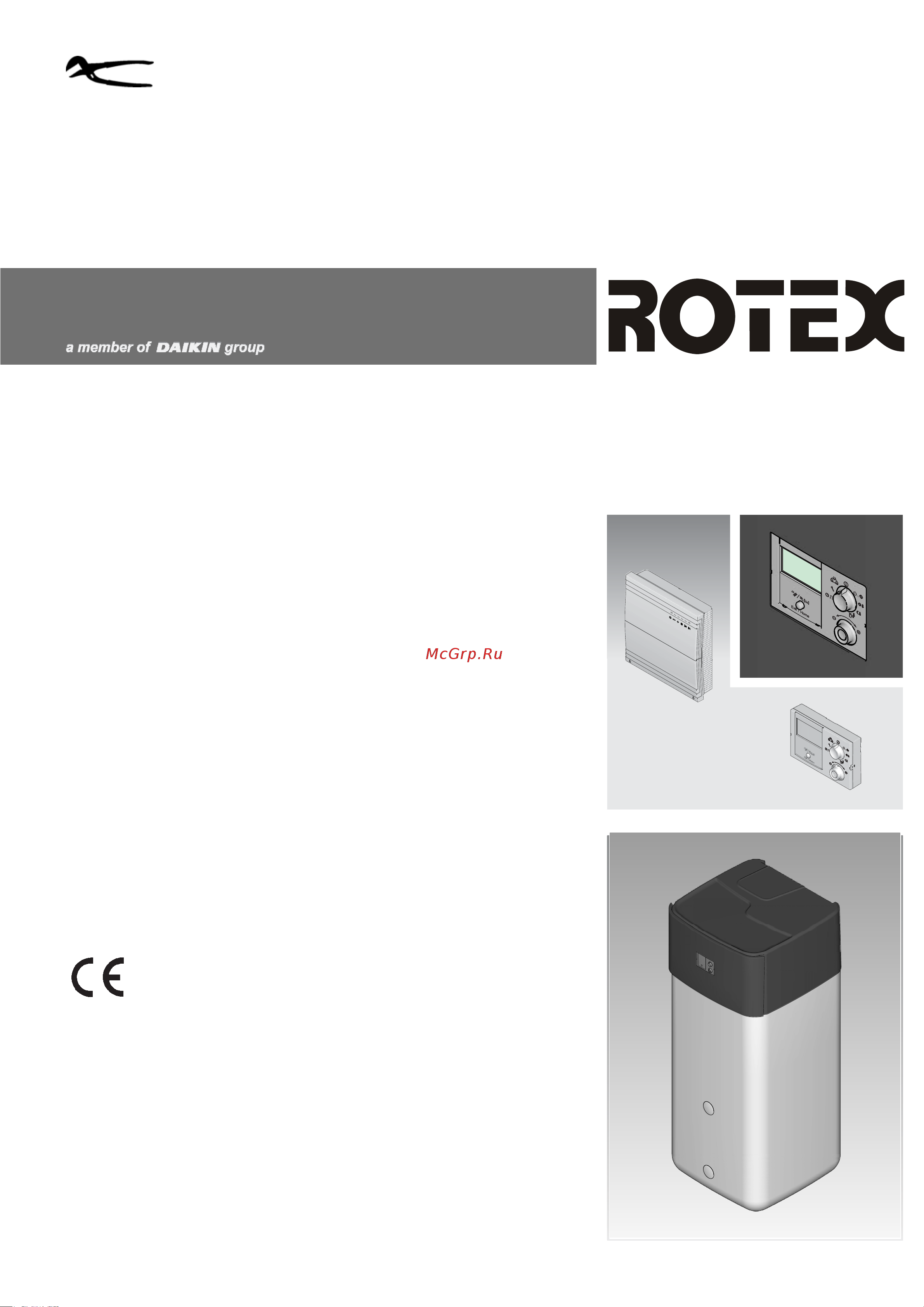
ROTEX Control unit
RoCon mb,
RoCon U1,
RoCon M1
Operating instructions
Electronic controller for heat pumps
For ROTEX HPSU monobloc compact types
RKHWMX300C
RKHWMX500C
RKHWMXB300C
RKHWMXB500C
GB
Edition 09/2017
Содержание
- Rotex control unit rocon mb rocon u1 rocon m1 operating instructions 1
- After first commissioning after successful basic configuration 37 2
- Avoiding danger 5 2
- Basic functions and operating modes 10 2
- Commissioning rotex hpsu monobloc compact 33 2
- Errors malfunctions and messages 55 2
- Explanation of the parameter tables 40 2
- For first commissioning or resetting to factory settings 36 2
- Fundamental aspects of the ids and authorisations in the rocon system 31 2
- General 7 2
- Initial start up 31 2
- List of contents 2
- Operating concept 9 2
- Operating support during 1st commissioning and during system extensions 32 2
- Operation 7 2
- Parameter levels for the rocon m1 mixer module 38 2
- Parameter overview 36 2
- Parameter settings 40 2
- Product description 6 2
- Putting optional rocon system components into operation 33 2
- Recognising errors correcting malfunctions 55 2
- Refer to the manual 4 2
- Rocon m1 mixer module 51 2
- Rotary switch setting configuration 40 2
- Rotary switch setting dhw install 47 2
- Rotary switch setting dhw set temp 48 2
- Rotary switch setting info 49 6 1 exit key special function 50 6 2 basic configuration parameter level 51 6 3 parameter levels of the 2
- Rotary switch setting operating mode 48 2
- Rotary switch setting remote param 49 2
- Rotary switch setting set temp day 48 2
- Rotary switch setting set temp night 48 2
- Rotary switch setting time program 49 2
- Safety 4 2
- Special functions 20 2
- Special system settings 21 2
- Use as intended 5 2
- Warning signs and explanation of symbols 4 2
- Glossary 7 3
- List of contents 3
- List of keywords 3 3
- Notes 8 3
- Meaning of the warnings 4
- Refer to the manual 4
- Safety 4
- Warning signs and explanation of symbols 4
- X safety 4
- Avoiding danger 5
- Handling instructions 5
- Order number 5
- Use as intended 5
- Validity 5
- X safety 5
- Product description 6
- X product description 6
- Danger 7
- Display 7
- Display and operating elements 7
- General 7
- If electrical components come into contact with water this can cause an electric shock as well as cause potentially fatal burns or injuries 7
- Maximum energy exploitation 7
- Operation 7
- The displays and the keys of the control unit must be protected against the effects of moisture 7
- To clean the control unit use a dry cotton cloth using aggressive cleaning agents and other fluids can cause damage to devices or lead to an electric shock 7
- X operation 7
- Caution 8
- Controls 8
- Explanation of symbols 8
- Never operate the operating elements of the control unit with a hard pointed object this can cause damage and can cause the control to malfunction 8
- Rotary switch 8
- X operation 8
- Exit key 9
- Operating concept 9
- Rotary button 9
- X operation 9
- Automatic defrost function 10
- Basic functions and operating modes 10
- Keylock 10
- System information info 10
- X operation 10
- Displaying the operating data overview 11
- X operation 11
- A heating system that is not protected against frost can freeze in the event of frost and thus be damaged 12
- Add glycol to the heating water circuit see installation and maintenance instructions 12
- Alternatively drain the heating system on the water side if there is a danger of frost 12
- Caution 12
- Displaying the water pressure 12
- If the heating system is not drained the power supply must be ensured and the external main switch must remain switched on if there is a danger of frost 12
- Operating mode standby stand by 12
- Setting the operating mode 12
- X operation 12
- Operating mode automatic 1 time program 13
- Operating mode automatic 2 time program 13
- Operating mode reducing 13
- Operating mode summer 13
- Operating modes heating cooling 13
- X operation 13
- Setting 14
- Switching time program 14
- Temperature setting of daytime room temperature 14
- Temperature setting of hot water generation 14
- Temperature setting of setback mode 14
- Unscheduled hot water preparation 14
- X operation 14
- Permanent time programs 15
- X operation 15
- Temporary time programs 16
- X operation 16
- Setting the lcd display language date time 17
- System settings 17
- Terminal function 17
- X operation 17
- Activating deactivating terminal operation 18
- Activating deactivating whisper mode 18
- Caution 18
- During active whisper mode the output in room heating and room cooling mode decreases such that it may no longer be possible to achieve pre set target temperature values 18
- Operation with glycol 18
- Whisper mode 18
- With outside temperatures below freezing there is a risk of material damage caused by frost 18
- X operation 18
- Activating deactivating emergency automatic operation 19
- Bution line e g vta32 15 60 15 screw 19
- Due to such forced charging the target hot water temperature in the hot water storage tank can exceed 60 c 19
- Ehs emergency operation 19
- Install scald protection in the hot water distri 19
- Set 1 15 60 16 19
- Smart grid sg 19
- There is a danger of scalding at target hot water temperatures over 60 c this is possible as the utility company evu is entitled to control current draw optimised according to supply and demand in the definitions for smart grid 19
- This storage tank charging is carried out even when standby operating mode is set 19
- Warning 19
- X operation 19
- 3 way switching valves reference travel 20
- Manual operation 20
- Special functions 20
- Way switching valves reference travel 20
- X operation 20
- Access rights technician code 21
- Caution risk of overheating of floor heating 21
- Connect an overheating protection switch in the building at the ext plug connection to external operating mode switch over so that the rotex hpsu monobloc compact is switched to standby or summer operating mode see chap 3 with parameter room thermostat on or parameter interlink fct on the overheating protection switch must be connected so that the room thermostat s switching contact is interrupted 21
- Expert 21
- Heat slope 21
- If the floor heating is also used for room cooling the connection notes in the above point also apply to the connection of a moisture protection switch in the building 21
- In the event of malfunction or during manual operation the floor heating the screed or the floor structure could be damaged due to over heating 21
- Prior to initial commissioning of the floor heating system set the maximum temper ature limit in the rocon mb controller parameter t vbh1 max and the maximum permissible system temperature parameter max t flow 21
- Special system settings 21
- X operation 21
- Caution risk of condensation 22
- Cooling slope 22
- In the event of malfunction or incorrect parame ter settings the floor heating the screed or the floor structure could be damaged due to con densation 22
- Manually adjusting the heat slope 22
- Prior to initial commissioning and activation of cooling mode set the minimum temper ature limit to the minimum permissible system temperature in the rocon mb controller parameter min t flow cooling 22
- X operation 22
- Frost protection function 23
- Weather dependent t hs control 23
- With connected mixer module 23
- X operation 23
- Additional alternative heat generator 24
- Caution 24
- Design heat distribution areas with different design temperatures as hydraulically separate heating circuits if necessary design heating circuits with lim ited target feed temperatures as mixer cir cuits and regulate with a mixer module 24
- Interlink function 24
- Limit target feed temperatures to suitable temperature ranges 24
- Unsuitable feed temperatures can cause dam age to the floor heating system or dew formation on cooling surfaces 24
- X operation 24
- Air purge 25
- Heating support 25
- Special function switching contacts 25
- X operation 25
- Anti legionella system 26
- Bution line e g vta32 15 60 15 screw 26
- Install scald protection in the hot water distri 26
- Option 1 26
- Option 2 26
- Resetting to factory settings reset 26
- Set 1 15 60 16 26
- There is a danger of scalding at target hot water temperatures over 60 c this is possible when using solar energy if the legionella protection or smart grid functions are activated or the target hot water temperature is set higher than 60 c 26
- Warning 26
- X operation 26
- Function heating 27
- Option 3 27
- Screed program 27
- X operation 27
- Screed curing heating 28
- Setting and starting the screed program 28
- X operation 28
- Defining the switching time program for the circulation pump 29
- Relay test 29
- Settings for optional circulation pump 29
- X operation 29
- Remote control via internet 30
- X operation 30
- Fundamental aspects of the ids and authorisations in the rocon system 31
- Initial start up 31
- X initial start up 31
- For all rocon b1 and rocon u1 control units 32
- For the rocon u1 room station 32
- Operating support during 1st commissioning and during system extensions 32
- X initial start up 32
- Assigning the terminal id on the rocon b1 control panel of the rotex hpsu monobloc compact 33
- Commissioning rotex hpsu monobloc compact 33
- Mixer module rocon m1 33
- Putting optional rocon system components into operation 33
- X initial start up 33
- A configuration for the living room setting 34
- B configuration for mixing valve setting 34
- Rocon u1 room station 34
- Sequence for initial commissioning see also chap 4 34
- X initial start up 34
- A heat generator 35
- Allocating the rocon m1 mixing module to 35
- Allocating the rocon m1 mixing module to a heat generator 35
- Caretaker function 35
- Master rocon function 35
- X initial start up 35
- During initial commissioning after resetting to factory settings 36
- For first commissioning or resetting to factory settings 36
- Parameter overview 36
- X parameter overview 36
- After first commissioning after successful basic configuration 37
- Fa rotex rocon mb 09 2017 37 37
- Rotary switch setting configuration 37
- X parameter overview 37
- Exit key special function 38
- Fa rotex rocon mb 09 2017 38
- Module 38
- No function 38
- Parameter levels for the rocon m1 mixer 38
- Parameter levels for the rocon m1 mixer module 38
- Rotary switch setting dhw install 38
- Rotary switch setting dhw set temp 38
- Rotary switch setting info 38
- Rotary switch setting operating mode 38
- Rotary switch setting remote param 38
- Rotary switch setting set temp day 38
- Rotary switch setting set temp night 38
- Rotary switch setting time program 38
- See chap 5 38
- X parameter overview 38
- Fa rotex rocon mb 09 2017 39 39
- Rotary switch setting configuration 39
- Rotary switch setting remote param 39
- Rotary switch setting time program 39
- See chap 5 39
- Tab 5 12 parameters in the configuration rotary switch setting 39
- X parameter overview 39
- Explanation of the parameter tables 40
- Parameter settings 40
- Rotary switch setting configuration 40
- Setup level 40
- X parameter settings 40
- Fa rotex rocon mb 09 2017 41 41
- X parameter settings 41
- Fa rotex rocon mb 09 2017 42
- X parameter settings 42
- Fa rotex rocon mb 09 2017 43 43
- Tab 6 1 parameters in the configuration rotary switch setting setup level 43
- X parameter settings 43
- Fa rotex rocon mb 09 2017 44
- System configuration level 44
- X parameter settings 44
- Depending on the version individual information pa rameters are displayed that are not described in tab 6 2 for this see tab 6 12 45
- Fa rotex rocon mb 09 2017 45 45
- Hc configuration level 45
- Tab 6 2 parameters in the configuration rotary switch setting system configuration level 45
- X parameter settings 45
- Fa rotex rocon mb 09 2017 46
- X parameter settings 46
- Dhw configuration level 47
- Fa rotex rocon mb 09 2017 47 47
- Rotary switch setting dhw install 47
- X parameter settings 47
- Fa rotex rocon mb 09 2017 48
- Rotary switch setting dhw set temp 48
- Rotary switch setting operating mode 48
- Rotary switch setting set temp day 48
- Rotary switch setting set temp night 48
- Tab 6 6 parameters in the operating mode rotary switch setting 48
- Tab 6 7 parameters in the set temp day rotary switch setting 48
- Tab 6 8 parameters in the set temp night rotary switch setting 48
- Tab 6 9 parameters in the dhw set temp rotary switch setting 48
- X parameter settings 48
- Fa rotex rocon mb 09 2017 49 49
- Rotary switch setting info 49
- Rotary switch setting remote param 49
- Rotary switch setting time program 49
- Tab 6 10 parameters in the time program rotary switch setting 49
- Tab 6 11 parameters in the remote param rotary switch setting 49
- X parameter settings 49
- Exit key special function 50
- Fa rotex rocon mb 09 2017 50
- Tab 6 12 parameters in the info rotary switch setting 50
- Tab 6 13 parameters at the special level level 50
- To enter press the exit button for at least 5 s 50
- X parameter settings 50
- After the system config parameter has been set to inactive or delete in the configuration rotary switch setting 51
- An unlimited scope of available parameters exists at the indi vidual levels 51
- Basic configuration parameter level 51
- Fa rotex rocon mb 09 2017 51 51
- No function 51
- On setting a control panel to mix valve x terminal function the displayed values refer to the components pump mix valve connected to the rocon m1 of the mixer circuit assigned via the device id 51
- On setting a rocon u1 room station assigned to the mixer module via the heating circuit id to living room the parameter t room adj is available the target room temperature can be changed in the range 5 k to 5 k with the rotary button this function is not available if the rocon u1 is used as a remote control in terminal function 51
- Only the corresponding sections are referred to below signif icant differences are explained in more detail 51
- Parameter levels of the rocon m1 mixer module 51
- Rotary switch setting configuration 51
- Rotary switch setting dhw install 51
- Rotary switch setting dhw set temp 51
- Rotary switch setting info 51
- Rotary switch setting operating mode 51
- Rotary switch setting remote param 51
- Rotary switch setting set temp day 51
- Rotary switch setting set temp night 51
- Rotary switch setting time program 51
- See chap 6 51
- See chap 6 0 51
- See chap 6 3 and 6 3 51
- Setup level 51
- The parameter levels parameter meanings setting ranges and connected functions are basically described in the same way as in the previous sections 51
- This parameter level only appears during initial commissioning if the answer selected for the use standard config prompt was no or 51
- X parameter settings 51
- Fa rotex rocon mb 09 2017 52
- Rotary switch setting configuration setup level 52
- Tab 6 15 parameters in the configuration rotary switch setting setup level 52
- X parameter settings 52
- Fa rotex rocon mb 09 2017 53 53
- Rotary switch setting configuration mixer config level 53
- X parameter settings 53
- Fa rotex rocon mb 09 2017 54
- Tab 6 16 parameters in the configuration rotary switch setting mixer config level 54
- X parameter settings 54
- Caution 55
- Current error display 55
- Electrostatic charges can lead to voltage arcing that can destroy the electronic components 55
- Errors malfunctions and messages 55
- Reading out the protocol 55
- Recognising errors correcting malfunctions 55
- Secure potential equalisation before touching electronic parts e g by touching an earthed metallic part 55
- Troubleshooting 55
- X errors malfunctions and messages 55
- Ehs emergency operation 56
- Emergency operation 56
- Malfunctions and fault codes 56
- X errors malfunctions and messages 56
- Glossary 57
- X glossary 57
- Switching time program 58
- User specific settings 58
- X notes 58
- Circulation time 59
- Enter the parameter changes you have made in the following table and in the rotex hpsu monobloc compact operating manual 59
- Fa rotex rocon mb 09 2017 59 59
- Ids in the rocon can bus system 59
- Parameters 59
- Rocon device id comments 59
- X notes 59
- Other items 60
- List of keywords 63
- X list of keywords 63
Похожие устройства
- Daikin RKHWMXB500C Инструкция по монтажу
- Daikin RKHW16MX500C Инструкция по эксплуатации
- Daikin RKHW16MX500C Инструкция по монтажу
- Daikin RKHW16MXB500C Инструкция по эксплуатации
- Daikin RKHW16MXB500C Инструкция по монтажу
- Daikin EKHWP300B Схема
- Daikin EKHWP300B Инструкция по эксплуатации
- Daikin EKHWP300B Руководство по эксплуатации
- Daikin EKHWP54419BA Схема
- Daikin EKHWP54419BA Инструкция по эксплуатации
- Daikin EKHWP54419BA Руководство по эксплуатации
- Daikin EKHWP500B Схема
- Daikin EKHWP500B Инструкция по эксплуатации
- Daikin EKHWP500B Руководство по эксплуатации
- Daikin EKHWP300PB Схема
- Daikin EKHWP300PB Инструкция по эксплуатации
- Daikin EKHWP300PB Руководство по эксплуатации
- Daikin EKHWP500PB Схема
- Daikin EKHWP500PB Инструкция по эксплуатации
- Daikin EKHWP500PB Руководство по эксплуатации