
Aten PG95230 Руководство пользователя онлайн
Терминология
Номер модели, не имеющий окончания -B, -B2 или -G, относится ко всем
модификациям модели. Например, номер PG98230 относится ко всем
модификациям – PG98230B, PG98230B2 и PG98230G.
A
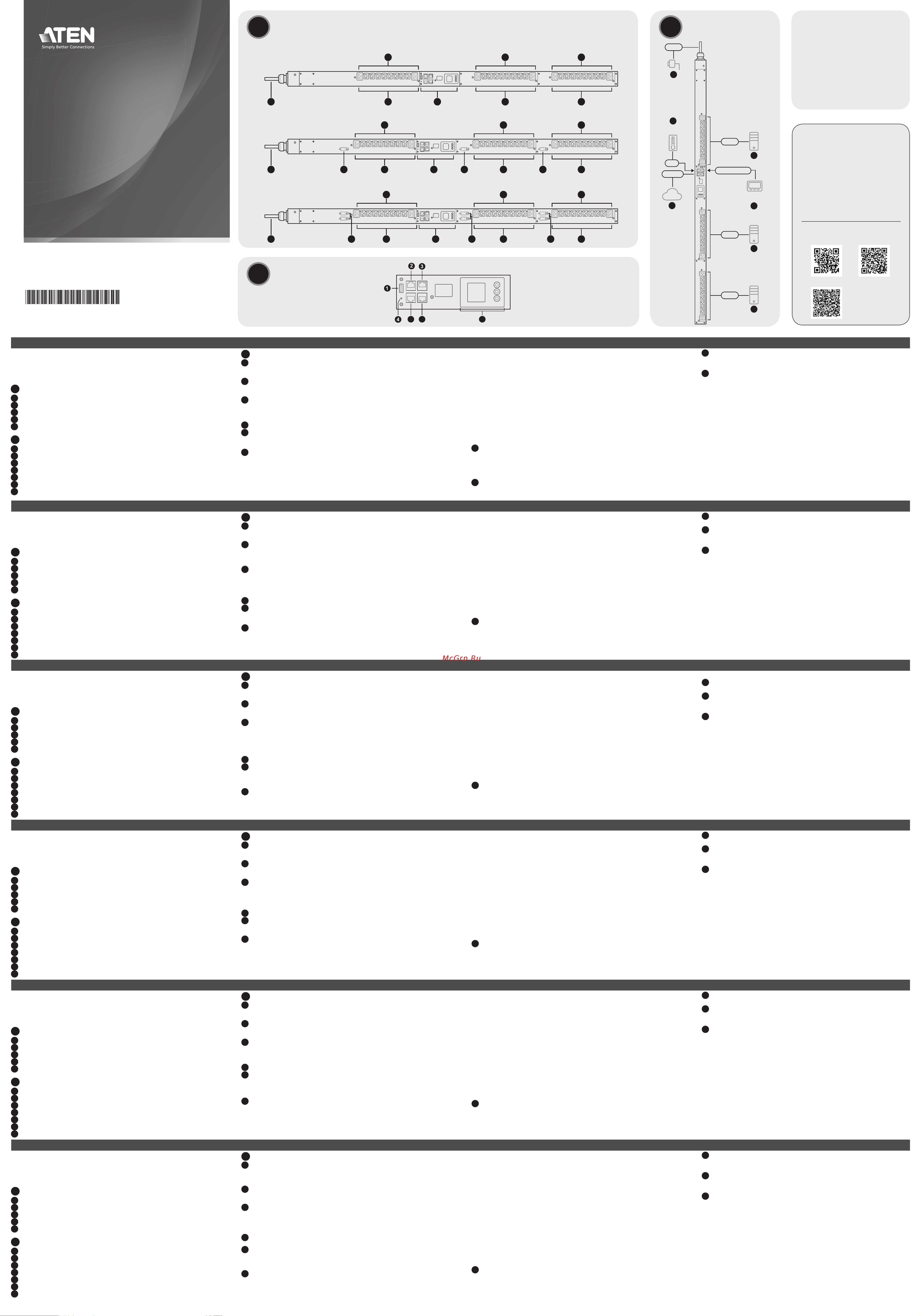
Основные элементы
1
Розетки питания
2
Панель состояния
3
Размыкатели (не применимо к PG95230 / PG96230 / PG98230)
4
Кабель питания
5
Индикаторы состояния розеток (не применимо к PG95230 / PG95330)
B
Панель состояния
1
Порт USB-A (для обновления микропрограммы/экспорта журнала)
2
Порт COM + PON
3
Порт LAN 1 (10/100/1000M)
4
Кнопка сброса
5
Порт датчика
6
Порт LAN 2 (10/100M)
7
ЖК-панель
3-фазный 30-розеточный БРП в форм-факторе 0U
www.aten.com
C
Установка
1
Обеспечьте надлежащее заземление блока.
Примечание: Не пропускайте это действие. Надлежащее заземление
помогает предотвратить повреждение блока из-за перепадов напряжения
или разрядов статического электричества.
2
Подсоедините кабели питания на входах питания переменного тока
каждого подключаемого устройства к свободным розеткам питания на
БРП. Закрепите кабели держателями кабелей ATEN Lok-U-Plug.
3
Подключите порт LAN 1 (10/100/1000M) или LAN 2 (10/100M) на блоке к сети
с помощью кабеля Ethernet. Для резервирования сетевых соединений можно
подключить к сети оба порта LAN с помощью 2-х кабелей Ethernet.
Примечание: Порты LAN можно использовать для каскадного
подключения до 64 БРП.
4
(Дополнительно) Подсоедините датчик окружающей среды к порту датчика
на блоке.
5
(Дополнительно) Подсоедините последовательный контроллер RS-232/
RS-485 к порту COM на блоке.
Примечание: Этот порт также можно использовать в качестве порта
PON для подключения к коммутатору KVM-по-IP по кабелю Ethernet.
6
Подсоедините встроенный кабель питания блока к источнику питания
переменного тока, тем самым включив БРП, а затем включите
подсоединенные устройства.
Позиции фиксации при стоечном монтаже
При выполнении стоечного монтажа следует использовать надлежащие
позиции винтов на задней панели блока, соответствующие выбранному
сценарию монтажа. См. раздел Позиции фиксации при стоечном монтаже
в руководстве пользователя.
• T1: Сценарий T1 следует использовать при монтаже БРП в стойке ATEN с
протягиванием кабеля питания блока к верхней части стойки.
• B1: Сценарий B1 следует использовать при монтаже БРП в стойке ATEN с
протягиванием кабеля питания блока к нижней части стойки.
• T: Сценарий T следует использовать при монтаже БРП в стойке сторонних
производителей с протягиванием кабеля питания блока к верхней части стойки.
• B: Сценарий B следует использовать при монтаже БРП в стойке сторонних
производителей с протягиванием кабеля питания блока к нижней части стойки.
Эксплуатация
Для управления блоком БРП компании ATEN и подключенными к нему
устройствами используются следующие 3 метода: браузер, eco DC и SNMP.
Браузер
1
Откройте браузер и введите в адресной строке браузера IP-адрес БРП, к
которому вы хотите получить доступ.
Примечание: IP-адрес по умолчанию: 192.168.0.60 для LAN 1 и
192.168.0.61 для LAN 2. IP-адрес можно узнать у администратора БРП
либо в разделе Определение IP-адреса руководства пользователя
2
При появлении диалогового окна с предупреждением системы
безопасности примите сертификат – ему можно доверять. Появится
страница входа в систему.
3
Укажите действительное имя пользователя и пароль.
Примечание: При первом входе в систему используйте имя
пользователя и пароль по умолчанию: administrator и password.
4
Нажмите кнопку Войти, чтобы перейти на главную страницу.
eco DC
Все БРП от ATEN поддерживают интерфейс «eco DC» (веб-интерфейс
управления энергоснабжением и DCIM) компании ATEN. Удобный и
интуитивно понятный пользовательский интерфейс «eco DC» позволяет
настраивать БРП и контролировать состояние питания всего подключенного
оборудования. Для установки этого программного обеспечения сосканируйте
QR-код «eco DC», чтобы перейти на веб-страницу продукта, а затем на
вкладке «Поддержка и загрузки» загрузите программу установки.
SNMP
Блоки БРП поддерживают любые сторонние программы управления по
протоколу SNMP версий V1, V2 или V3. Для установки этого программного
обеспечения сосканируйте QR-код «ATEN Website», чтобы перейти на веб-
страницу продукта, а затем на вкладке «Поддержка и загрузки» загрузите
программу установки.
Uso dei termini
Un numero di modello che non fi nisca con B, B2 o G indica tutte le varianti del
modello. Per esempio, PG98230 si riferisce a PG98230B, PG98230B2, e PG98230G
senza distinzioni.
A
Panoramica dell’Hardware
1
uscite alimentazione
2
pannello di stato
3
interruttori (non applicabile a PG95230 / PG96230 / PG98230)
4
cavo di alimentazione
5
LED di stato dell’alimentazione (non applicabile a PG95230 / PG95330)
B
Pannello di stato
1
Porta USB di tipo A (aggiornamento fi rmware / esportazione registri)
2
Porta COM + PON
3
LAN 1 (10/100/1000M)
4
pulsante di ripristino
5
porta per i sensori
6
LAN 2 (10/100M)
7
Pannello LCD
Eco PDU 30-Outlet 0U a 3 fasi
www.aten.com
C
Installazione
1
Assicurati che le unità sia adeguatamente messa a terra.
Nota: Non saltare questo passaggio. La messa a terra adeguata aiuta a prevenire
danni all’unità dovuti a sovraccarico o elettricità statica.
2
Per ciascun dispositivo che vuoi connettere, usa il suo cavo di alimentazione per
connettere la presa di alimentazione del dispositivo a una presa libera sull’eco
PDU. Usa sostegni per cavi ATEN Lok-U-Plug per fi ssarli.
3
Collega la porta LAN 1 (10/100/1000M) o LAN 2 (10/100M) dell’unità a una rete
usando un cavo Ethernet. Per ridondanza di rete, si possono anche collegare alla
rete entrambe le porte LAN usando 2 cavi Ethernet.
Nota: Si possono anche usare le porte LAN per collegare in serie fi no a 64 eco PDU.
4
(Facoltativo) Collega un sensore ambientale alla porta per i sensori dell’unità.
5
(Facoltativo) Collega un comando seriale RS-232/RS-485 alla porta COM
dell’unità.
Nota: Si può anche usare la porta come porta PON, per collegare a uno Switch
ATEN KVM over IP tramite un cavo Ethernet.
6
Collega il cavo di alimentazione integrato dell’unità a una presa di corrente,
l’unità si accenderà; poi accendi i dispositivi collegati.
Posizioni di blocco per montaggio sul supporto
Quando si monta su un supporto, assicurarsi di mettere le viti nelle giuste posizioni,
sulla parte posteriore dell’unità, che corrispondono al tuo scenario di installazione.
Per maggiori dettagli vedi la sezione Posizioni di blocco per montaggio su supporto
del manuale di istruzioni.
• T1: Usa T1 per montare l’eco PDU su un supporto ATEN con il cavo di
alimentazione che si estende verso la parte superiore del supporto.
• B1: Usa B1 per montare l’eco PDU su un supporto ATEN con il cavo di
alimentazione che si estende verso la parte inferiore del supporto.
• T: Usa T per montare l’eco PDU su un supporto di terze parti con il cavo di
alimentazione che si estende verso la parte superiore del supporto.
• B: Usa B per montare l’eco PDU su un supporto di terze parti con il cavo di
alimentazione che si estende verso la parte inferiore del supporto.
Funzionamento
ATEN eco PDU fornisce 3 metodi per gestire l’unità e i suoi dispositivi alimentati:
browser, eco DC, e SNMP.
Browser
1
Apri un browser e specifi ca nella barra degli indirizzi l’indirizzo IP dell’eco PDU a
cui vuoi accedere.
Nota: L’indirizzo IP di default è 192.168.0.60 per LAN 1 e 192.168.0.61 per
Lan 2. Puoi ottenere l’indirizzo IP dall’amministratore dell’eco PDU, o vedere la
sezione Determinare l’indirizzo IP del manuale delle istruzioni
2
Qualora appaia un avviso di sicurezza, accetta il certifi cato — è attendibile.
Appare la pagina di accesso.
3
Fornire un nome utente e una password validi.
Nota: Per il primo accesso usa la password e il nome utente preimpostati:
administrator e password.
4
Clicca su Login per accedere alla pagina principale del browser.
eco DC
Tutti gli eco PDU ATEN supportano ATEN eco DC (Energy & DCIM Management Web
GUI). eco DC offre un’interfaccia d’uso grafi ca intuitiva e semplice da capire che
permette di confi gurare gli eco PDU e controllare lo stato di funzionamento di tutti
i dispositivi collegati. Per installare il software, scansiona il codice QR dell’eco DC
per visitare la pagina web del prodotto e scaricare il fi le di installazione dalla scheda
“Support and Downloads”.
SNMP
Gli eco PDU supportano tutti i software di gestione di terze parti SNMP V1, V2,
V3. Per installare il software, scansiona il codice QR del sito ATEN per visitare la
pagina web del prodotto e scaricare il fi le di installazione dalla scheda “Support and
Downloads”.
Uso de términos
Se utiliza un número de modelo sin la terminación -B, -B2 o -G para referirse a todas
las variantes del modelo. Por ejemplo, PG98230 se refi ere a PG98230B, PG98230B2
y PG98230G en conjunto.
A
Vista general del hardware
1
enchufes de electricidad
2
panel de estado
3
disyuntores (no aplicable a PG95230 / PG96230 / PG98230)
4
cable de alimentación
5
LED de estado de salida (no aplicable a PG95230 / PG95330)
B
Panel de estado
1
Puerto USB tipo A (actualización de fi rmware / exportación de registros)
2
Puerto COM + PON
3
LAN 1 (10/100/1000M)
4
botón Restablecer
5
puerto del sensor
6
LAN 2 (10/100M)
7
Panel LCD
PDU eco trifásica de 30 salidas y 0U
www.aten.com
C
Instalación
1
Asegúrese de que la unidad está debidamente conectada a tierra.
Nota: No omita este paso. La conexión a tierra adecuada ayuda a evitar daños
en la unidad por sobrecargas de energía o electricidad estática.
2
Para cada dispositivo que desee conectar, utilice su cable de alimentación para
conectar la entrada de alimentación de CA del dispositivo a cualquier toma disponible
en la eco PDU. Utilice soportes para cables ATEN Lok-U-Plug para asegurarlos.
3
Conecte el puerto LAN 1 (10/100/1000 M) o LAN 2 (10/100M) de la unidad a
una red mediante un cable Ethernet. Para redundancia de red, opcionalmente
conecte ambos puertos LAN a la red usando 2 cables Ethernet.
Nota: También puede usar los puertos LAN para conectar en cascada hasta 64
eco PDU.
4
(Opcional) Conecte un sensor ambiental al puerto del sensor de la unidad.
5
(Opcional) Conecte un controlador serial RS-232 / RS-485 al puerto COM de la unidad.
Nota: También puede utilizar el puerto como un puerto PON, conectándose a
un conmutador KVM sobre IP de ATEN a través de un cable Ethernet.
6
Conecte el cable de alimentación incorporado de la unidad a una fuente de
alimentación de CA, encendiéndola y luego encienda los dispositivos conectados.
Posiciones de bloqueo de montaje en bastidor
Al realizar el montaje en bastidor, asegúrese de utilizar las posiciones correctas de
los tornillos, en la parte posterior de la unidad, que correspondan a su situación de
instalación. Consulte la sección Posiciones de bloqueo de montaje en bastidor del
manual del usuario para obtener más detalles.
• T1: Utilice T1 para montar la eco PDU en un bastidor ATEN con el cable de
alimentación extendido hacia la parte superior del bastidor.
• B1: Utilice B1 para montar la eco PDU en un bastidor ATEN con el cable de
alimentación extendido hacia la parte inferior del bastidor.
• T: Utilice T para montar la eco PDU en un bastidor de otro fabricante con el cable
de alimentación extendido hacia la parte superior del bastidor.
• B: Utilice B para montar la eco PDU en un bastidor de otro fabricante con el cable
de alimentación extendido hacia la parte inferior del bastidor.
Funcionamiento
ATEN eco PDU proporciona 3 métodos para administrar la unidad y sus dispositivos
alimentados: navegador, eco DC y SNMP.
Explorador
1
Abra un navegador y especifi que la dirección IP de la eco PDU a la que desea
acceder en la barra de ubicación de URL del navegador.
Nota: La dirección IP predeterminada es 192.168.0.60 para LAN 1 y 192.168.0.61
para Lan 2. Puede obtener la dirección IP del administrador de eco PDU o consultar la
sección Determinación de la dirección IP del manual del usuario
2
Si aparece un cuadro de diálogo de Alerta de seguridad, acepte la certifi cación;
se puede confi ar en ella. Aparecerá la página de inicio de sesión.
3
Proporcione un nombre de usuario y una contraseña válidos.
Nota: Para iniciar sesión por primera vez, utilice el nombre de usuario y la
contraseña predeterminados: administrador y contraseña.
4
Haga clic en Iniciar sesión para abrir la página principal del navegador.
eco DC
Todas las eco PDU de ATEN son compatibles con ATEN eco DC (GUI web de gestión
de energía y DCIM). Eco DC ofrece una interfaz gráfi ca de usuario intuitiva y fácil de
usar que le permite confi gurar eco PDU y monitorear el estado de energía de todos
los equipos conectados. Para instalar el software, escanee el código QR de eco DC
para visitar la página web del producto y luego descargue el instalador desde la
pestaña Soporte y Descargas.
SNMP
Las eco PDU son compatibles con cualquier software de administrador SNMP V1, V2
y V3 de otro fabricante. Para instalar el software, escanee el código QR del sitio web
de ATEN para visitar la página web del producto y luego descargue el instalador
desde la pestaña Soporte y Descargas.
Verwendung von Begriffen
Eine Modellnummer ohne die Endung -B, -B2 oder -G wird verwendet, um sich
auf alle Varianten des Modells zu beziehen. PG98230 bezieht sich zum Beispiel auf
PG98230B, PG98230B2 und PG98230G insgesamt.
A
Hardware Übersicht
1
Stromanschlüsse
2
Statusleiste
3
Schutzschalter (gilt nicht für PG95230 / PG96230 / PG98230)
4
Netzkabel
5
Ausgangsstatus LEDs (gilt nicht für PG95230 / PG95330)
B
Statusleiste
1
USB Typ-A Anschluss (Firmware-Upgrade / Protokollexport)
2
COM + PON Anschluss
3
LAN 1 (10/100/1000M)
4
Reset Taste
5
Sensoranschluss
6
LAN 2 (10/100M)
7
LCD-Anzeige
3-Phasen 30-Ausgänge 0U eco PDU
www.aten.com
C
Installation
1
Stellen Sie sicher, dass das Gerät ordnungsgemäß geerdet sind.
Hinweis: Lassen Sie diesen Schritt nicht aus. Eine angemessene Erdung hilft bei der
Verhinderung von Geräteschäden durch Spannungsspitzen oder statische Elektrizität.
2
Verwenden Sie für jedes Gerät, das Sie anschließen möchten, das zugehörige
Netzkabel, um den Netzanschluss des Geräts mit einer beliebigen Steckdose der eco
PDU zu verbinden. Verwenden Sie ATEN Lok-U-Plug Kabelhalter, um sie zu sichern.
3
Verbinden Sie den LAN 1 (10/100/1000M) oder LAN 2 (10/100M) Anschluss des
Geräts über ein Ethernet-Kabel mit einem Netzwerk. Für Netzwerkredundanz
können Sie optional beide LAN-Anschlüsse über 2 Ethernet-Kabel mit dem
Netzwerk verbinden.
Hinweis: Sie können die LAN-Anschlüsse auch verwenden, um bis zu 64 eco
PDUs zu kaskadieren.
4
(Optional) Schließen Sie einen Umgebungssensor an den Sensoranschluss des Geräts an.
5
(Optional) Schließen Sie einen seriellen RS-232/RS-485 Controller an den COM-
Anschluss des Geräts an.
Hinweis: Sie können den Anschluss auch als PON-Anschluss verwenden, indem
Sie ihn über ein Ethernet-Kabel mit einem ATEN KVM over IP Switch verbinden.
6
Schließen Sie das integrierte Netzkabel des Geräts an eine Wechselstromquelle
an, um es einzuschalten, und schalten Sie dann die angeschlossenen Geräte ein.
Positionen der Rackmontageverriegelung
Achten Sie bei der Montage in einem Rack darauf, dass Sie die richtigen
Schraubenpositionen an der Rückseite des Geräts verwenden, die Ihrer
Einbausituation entsprechen. Einzelheiten dazu fi nden Sie im Abschnitt Positionen
der Rackmontageverriegelung des Benutzerhandbuchs.
• T1: Verwenden Sie T1, um die eco PDU so in ein ATEN Rack einzubauen, dass das
Netzkabel nach oben aus dem Rack herausragt.
• B1: Verwenden Sie B1, um die eco PDU so in ein ATEN Rack einzubauen, dass das
Netzkabel nach unten aus dem Rack herausragt.
• T: Verwenden Sie T, um die eco PDU so in ein Rack eines Drittanbieters
einzubauen, dass das Netzkabel nach oben aus dem Rack herausragt.
• B: Verwenden Sie B, um die eco PDU so in ein Rack eines Drittanbieters
einzubauen, dass das Netzkabel nach unten aus dem Rack herausragt.
Bedienung
Die ATEN eco PDU bietet 3 Methoden zur Verwaltung des Geräts und der
angeschlossenen Geräte: Browser, eco DC und SNMP.
Browser
1
Öffnen Sie einen Browser und geben Sie in der URL Adressleiste Ihres Browsers
die IP-Adresse der eco PDU ein, auf die Sie zugreifen möchten.
Hinweis: Die Standard IP-Adresse lautet 192.168.0.60 für LAN 1 und
192.168.0.61 für Lan 2. Sie können die IP-Adresse von Ihrem eco PDU
Administrator beziehen oder im Kapitel Ermittlung der IP-Adresse des
Benutzerhandbuchs nachschlagen
2
Falls ein Sicherheitshinweis erscheint, akzeptieren Sie das Zertifi kat — es ist
vertrauenswürdig. Daraufhin erscheint die Anmeldeseite.
3
Geben Sie einen gültigen Benutzernamen und das Passwort ein.
Hinweis: Für die erstmalige Anmeldung verwenden Sie den Standard
Benutzernamen und das Standard Passwort: administrator und password.
4
Klicken Sie auf Anmelden, um zur Browser Hauptseite zu gelangen.
eco DC
Alle ATEN eco PDUs unterstützen ATEN eco DC (Energy & DCIM Management Web
GUI). eco DC bietet eine intuitive und benutzerfreundliche grafi sche Benutzeroberfl äche,
mit der Sie eco PDUs konfi gurieren und den Energiestatus aller angeschlossenen Geräte
überwachen können. Scannen Sie den eco DC QR-Code zur Installation der Software,
um die Produktwebseite zu besuchen, und laden Sie dann das Installationsprogramm von
der Registerkarte Support und Downloads herunter.
SNMP
eco PDUs unterstützen jede SNMP Manager Software von Drittanbietern (V1, V2 &
V3). Scannen Sie zur Installation der Software den QR-Code der ATEN Webseite, um
die Produktwebseite zu besuchen, und laden Sie dann das Installationsprogramm
von der Registerkarte Support und Downloads herunter.
Utilisation des termes
Un numéro de modèle sans la terminaison -B, -B2 ou -G est utilisé pour faire
référence à toutes les variantes du modèle. Par exemple, PG98230 désigne à la fois
PG98230B, PG98230B2 et PG98230G.
A
Survol du matériel
1
prises électriques
2
panneau d'état
3
disjoncteurs (ne s'applique pas aux PG95230 / PG96230 / PG98230)
4
cordon d'alimentation
5
LED d'état des prises (ne s'applique pas aux PG95230 / PG95330)
B
Panneau d'état
1
Port USB Type-A (mise à niveau du micrologiciel / exportation du journal)
2
Port COM + PON
3
LAN 1 (10/100/1000M)
4
bouton de réinitialisation
5
port de capteur
6
LAN 2 (10/100M)
7
Panneau LCD
PDU éco triphasée à 30 prises 0U
www.aten.com
C
Installation
1
Assurez-vous que l'unité est correctement reliée à la terre.
Remarque : N'ignorez pas cette étape. Une mise à terre appropriée permet d'éviter
que l'unité ne soit endommagée par des surtensions ou de l'électricité statique.
2
Pour chaque appareil que vous souhaitez connecter, utilisez son câble
d'alimentation pour connecter l'entrée d'alimentation CA de l'appareil à
n'importe quelle prise disponible sur la PDU éco. Utilisez les supports de câble
ATEN Lok-U-Plug pour les fi xer.
3
Connectez le port LAN 1 (10/100/1000M) ou LAN 2 (10/100M) de l'unité à un
réseau à l'aide d'un câble Ethernet. Pour la redondance du réseau, connectez
éventuellement les deux ports LAN au réseau à l'aide de 2 câbles Ethernet.
Remarque : Vous pouvez également utiliser les ports LAN pour mettre en
cascade jusqu'à 64 PDU éco.
4
(En option) Connectez un capteur environnemental au port de capteur de l'unité.
5
(En option) Connectez un contrôleur série RS-232/RS-485 au port COM de l'unité.
Remarque : Vous pouvez également utiliser le port comme un port PON, en le
connectant à un commutateur KVM sur IP ATEN via un câble Ethernet.
6
Connectez le cordon d'alimentation intégré de l'unité à une source d'alimentation
CA, ce qui la met sous tension, puis mettez sous tension les appareils connectés.
Positions de verrouillage du montage en rack
Lors du montage sur un rack, veillez à utiliser les positions de vis correctes, à l'arrière
de l'unité, qui correspondent à votre scénario d'installation. Reportez-vous à la
section Positions de verrouillage du montage en rack du manuel de l'utilisateur pour
plus de détails.
• T1 : Utilisez T1 pour monter la PDU éco sur un rack ATEN avec son cordon
d'alimentation s'étendant vers le haut du rack.
• B1 : Utilisez B1 pour monter la PDU éco sur un rack ATEN avec son cordon
d'alimentation s'étendant vers le bas du rack.
• T : Utilisez T pour monter la PDU éco sur un rack tiers avec son cordon
d'alimentation s'étendant vers le haut du rack.
• B : Utilisez B pour monter la PDU éco sur un rack tiers avec son cordon
d'alimentation s'étendant vers le bas du rack.
Fonctionnement
La PDU éco ATEN offre 3 méthodes pour gérer l'unité et ses appareils alimentés :
navigateur, eco DC et SNMP.
Navigateur
1
Ouvrez un navigateur et indiquez l'adresse IP de la PDU éco à laquelle vous
souhaitez accéder dans la barre de localisation d'URL du navigateur.
Remarque : L'adresse IP par défaut est 192.168.0.60 pour LAN 1 et 192.168.0.61
pour Lan 2. Vous pouvez obtenir l'adresse IP de l'administrateur de la PDU éco ou
consulter la section Détermination de l'adresse IP du manuel de l'utilisateur
2
Si une boîte de dialogue d'alerte de sécurité s'affi che, acceptez la certifi cation –
digne de confi ance. La page de connexion apparaît.
3
Fournissez un nom d'utilisateur et un mot de passe valides.
Remarque : Pour la première connexion, utilisez le nom d'utilisateur et le mot
de passe par défaut : administrateur et mot de passe.
4
Cliquez sur Connexion pour affi cher la page principale du navigateur.
eco DC
Toutes les PDU éco ATEN prennent en charge eco DC ATEN (Interface graphique
Web de gestion de l'énergie et du DCIM). eco DC offre une interface utilisateur
graphique intuitive et conviviale qui vous permet de confi gurer les PDU éco et de
surveiller l'état de l'alimentation de tous les équipements connectés. Pour installer
le logiciel, scannez le code QR eco DC pour visiter la page Web du produit, puis
téléchargez le programme d'installation depuis l'onglet Support et téléchargements.
SNMP
Les PDU éco prennent en charge tout logiciel gestionnaire tiers V1, V2 et V3 SNMP.
Pour installer le logiciel, scannez le code QR du site Web ATEN pour visiter la page
Web du produit, puis téléchargez le programme d'installation depuis l'onglet
Support et téléchargements.
5 6 7
Usage of Terms
A model number without the -B, -B2, or -G ending is used to refer to all variants
of the model. For example, PG98230 refers to PG98230B, PG98230B2, and
PG98230G altogether.
A
Hardware Overview
1
power outlets
2
status panel
3
circuit breakers (not applicable to PG95230 / PG96230 / PG98230)
4
power cord
5
outlet status LEDs (not applicable to PG95230 / PG95330)
B
Status Panel
1
USB Type-A port (fi rmware upgrade / log export)
2
COM + PON port
3
LAN 1 (10/100/1000M)
4
reset button
5
sensor port
6
LAN 2 (10/100M)
7
LCD panel
B
Status Panel
© Copyright 2022 ATEN
®
International Co. Ltd.
ATEN and the ATEN logo are registered trademarks of ATEN International Co., Ltd.
All rights reserved. All other trademarks are the property of their respective owners.
Part No. PAPE-1223-Y30G Released: 11/2022
3-Phase 30-Outlet 0U eco PDU
Quick Start Guide
PG95230 / PG95330
PG96230 / PG96330
PG98230 / PG98330
3-Phase 30-Outlet 0U eco PDU
www.aten.com
A
Hardware Overview
Package Contents
1 3-Phase 30-Outlet 0U
eco PDU unit
1 rack mount kit
1 RJ-45 to DB-9 cable
1 full-panel colored sticker
1 user instructions
Support and Documentation Notice
All information, documentation, fi rmware,
software utilities, and specifi cations
contained in this package are subject to
change without prior notifi cation by the
manufacturer.
To reduce the environmental impact of
our products, ATEN documentation and
software can be found online at
http://www.aten.com/download/
Technical Support
www.aten.com/support
Scan for more information
ATEN Website (PG98230) User Manual
C
Installation
1
Make sure the unit is properly grounded.
Note: Do not omit this step. Proper grounding helps prevent damage to the unit
from power surges or static electricity.
2
For each device you want to connect, use its power cable to connect the device’s
AC power inlet to any available outlet on the eco PDU. Use ATEN Lok-U-Plug
cable holders to secure them.
3
Connect the unit’s LAN 1 (10/100/1000M) or LAN 2 (10/100M) port to a
network using an Ethernet cable. For network redundancy, optionally connect
both LAN ports to the network using 2 Ethernet cables.
Note: You can also use the LAN ports to cascade up to 64 eco PDUs.
4
(Optional) Connect an environmental sensor to the unit’s sensor port.
5
(Optional) Connect an RS-232/RS-485 serial controller to the unit's COM port.
Note: You can also use the port as a PON port, connecting to an ATEN KVM
over IP Switch via an Ethernet cable.
6
Connect the unit’s built-in power cord to an AC power source,
thereby turning it on, and then turn on the connected devices.
Rack Mount Lock Positions
When mounting onto a rack, make sure to use the correct screw positions, at the
rear of the unit, that correspond to your installation scenario. Refer to the Rack
Mount Lock Positions section of the user manual for details.
• T1: Use T1 to mount the eco PDU onto an ATEN rack with its power cord
extending toward the top of the rack.
• B1: Use B1 to mount the eco PDU onto an ATEN rack with its power
cord extending toward the bottom of the rack.
• T: Use T to mount the eco PDU onto a 3rd-party rack with its power
cord extending toward the top of the rack.
• B: Use B to mount the eco PDU onto a 3rd-party rack with its power cord
extending toward the bottom of the rack.
Operation
ATEN eco PDU provides 3 methods for managing the unit and its powered devices:
browser, eco DC, and SNMP.
Browser
1
Open a browser and specify the IP address of the eco PDU you want to access in
the browser’s URL location bar.
Note: The default IP address is 192.168.0.60 for LAN 1 and 192.168.0.61 for
Lan 2. You can get the IP address from the eco PDU administrator, or see the IP
Address Determination section of the user manual
.
2
If a Security Alert dialog box appears, accept the certifi cation — it can be
trusted. The login page appears.
3
Provide a valid username and password.
Note: For fi rst-time login, use the default username and password:
administrator and password.
4
Click Login to bring up the browser main page.
eco DC
All ATEN eco PDUs support ATEN eco DC (Energy & DCIM Management Web GUI).
eco DC offers an intuitive and user-friendly graphical user interface that allows you
to confi gure eco PDUs and monitor the power status of all equipment connected.
To install the software, scan the eco DC QR code to visit the product web page, and
then download the installer from the Support and Downloads tab.
SNMP
eco PDUs support any 3rd party V1, V2 & V3 SNMP Manager Software. To install the
software, scan the ATEN Website QR code to visit the product web page, and then
download the installer from the Support and Downloads tab.
PG95230 / PG96230 / PG98230 Front View
5
14
5
1
5
12
PG95330B / PG95330B2 / PG96330B / PG96330B2 / PG98330B / PG98330B2 Front View
5
14
5
1
5
123 3 3
PG95330G / PG96330G / PG98330G Front View
5
14
5
1
5
123 3 3
4
6
3
2
5
Power
Ethernet
RJ-45
RS-232 / RS-485
Hardware /
Software Controller
PC x 10
2
Power
PC x 10
2
Power
PC x 10
Network
Temperature
Sensor
Power
C
Installation
ATEN Website (eco DC)
Содержание
- Bedienung 1
- Fonctionnement 1
- Funcionamiento 1
- Funzionamento 1
- Hardware overview 1
- Hardware übersicht 1
- Instalación 1
- Installation 1
- Installazione 1
- Operation 1
- Panel de estado 1
- Panneau d état 1
- Pannello di stato 1
- Panoramica dell hardware 1
- Pg95230 pg95330 pg96230 pg96330 pg98230 pg98330 1
- Phase 30 outlet 0u eco pdu quick start guide 1
- Status panel 1
- Statusleiste 1
- Survol du matériel 1
- Usage of terms 1
- Uso de términos 1
- Uso dei termini 1
- Utilisation des termes 1
- Verwendung von begriffen 1
- Vista general del hardware 1
- Основные элементы 1
- Панель состояния 1
- Терминология 1
- Установка 1
- Эксплуатация 1
- Browser 2
- Donanıma genel bakış 2
- Durum paneli 2
- Eco dc 2
- Funcionamento 2
- Instalare 2
- Instalação 2
- Kurulum 2
- Montaż 2
- Obsługa 2
- Operare 2
- Painel de estado 2
- Panel stanu systemu 2
- Panou de stare 2
- Posições de bloqueio de montagem em bastidor 2
- Poziții de fixare la montarea pe rack 2
- Pozycje blokowania przy montażu w szafie 2
- Prezentare hardware 2
- Przegląd sprzętu 2
- Przeglądarka 2
- Raf montajı kilitleme konumları 2
- Tarayıcı 2
- Terimlerin kullanımı 2
- Terminologia 2
- Utilizarea termenilor 2
- Utilização de termos 2
- Vista geral do hardware 2
- Çalıştırma 2
- Браузер 2
- Вживання термінів 2
- Встановлення 2
- Огляд обладнання 2
- Панель стану 2
- Позиції фіксаторів для монтажу в стійку 2
- Робота 2
- ステータスパネル 2
- セットアップ 2
- ブラウザ 2
- ラックマウントロック位置 2
- 使用條款 2
- 安装 2
- 安裝 2
- 操作 2
- 操作方法 2
- 术语使用 2
- 机架安装锁定位置 2
- 機架安裝鎖定位置 2
- 浏览器 2
- 瀏覽器 2
- 状态面板 2
- 狀態面板 2
- 用語の使用法 2
- 硬件概览 2
- 硬體檢視 2
- 製品各部名称 2
- 랙 마운트 잠금 위치 2
- 브라우저 2
- 상태 패널 2
- 설치 2
- 용어의 사용 2
- 작동 2
- 하드웨어 개요 2
Похожие устройства
- Aten PG95230 Краткое руководство по установке
- Aten PG95330 Краткое руководство по установке
- Aten PG95330 Руководство пользователя
- Aten PE5224TA Краткое руководство по установке
- Aten PE5224TA Руководство пользователя
- Aten PE5221T Краткое руководство по установке
- Aten PE5221T Руководство пользователя
- Aten PE5342TG Краткое руководство по установке
- Aten PE5342TG Руководство пользователя
- Aten PE5340SL Краткое руководство по установке
- Aten PE5340SL Руководство пользователя
- Aten PE5108 Удаленное управление терминалом
- Aten PE5108 Инструкция
- Aten PE5108 Краткое руководство по установке
- Aten PE5108 Руководство пользователя
- Aten PE5208 Удаленное управление терминалом
- Aten PE5208 Инструкция
- Aten PE5208 Краткое руководство по установке
- Aten PE5208 Руководство пользователя
- Aten PE1216 Руководство пользователя