
Legrand KEOR T 60 kVA Инструкция по эксплуатации онлайн
87045 LIMOGES Cedex
Phone number : (+33) 05 55 06 87 87 - Fax : (+33) 05 55 06 88 88
INDEX Page
1. General specifications ...........................1
2. Technical specifications ......................... 2
3 102 20 - 3 102 21 - 3 102 22
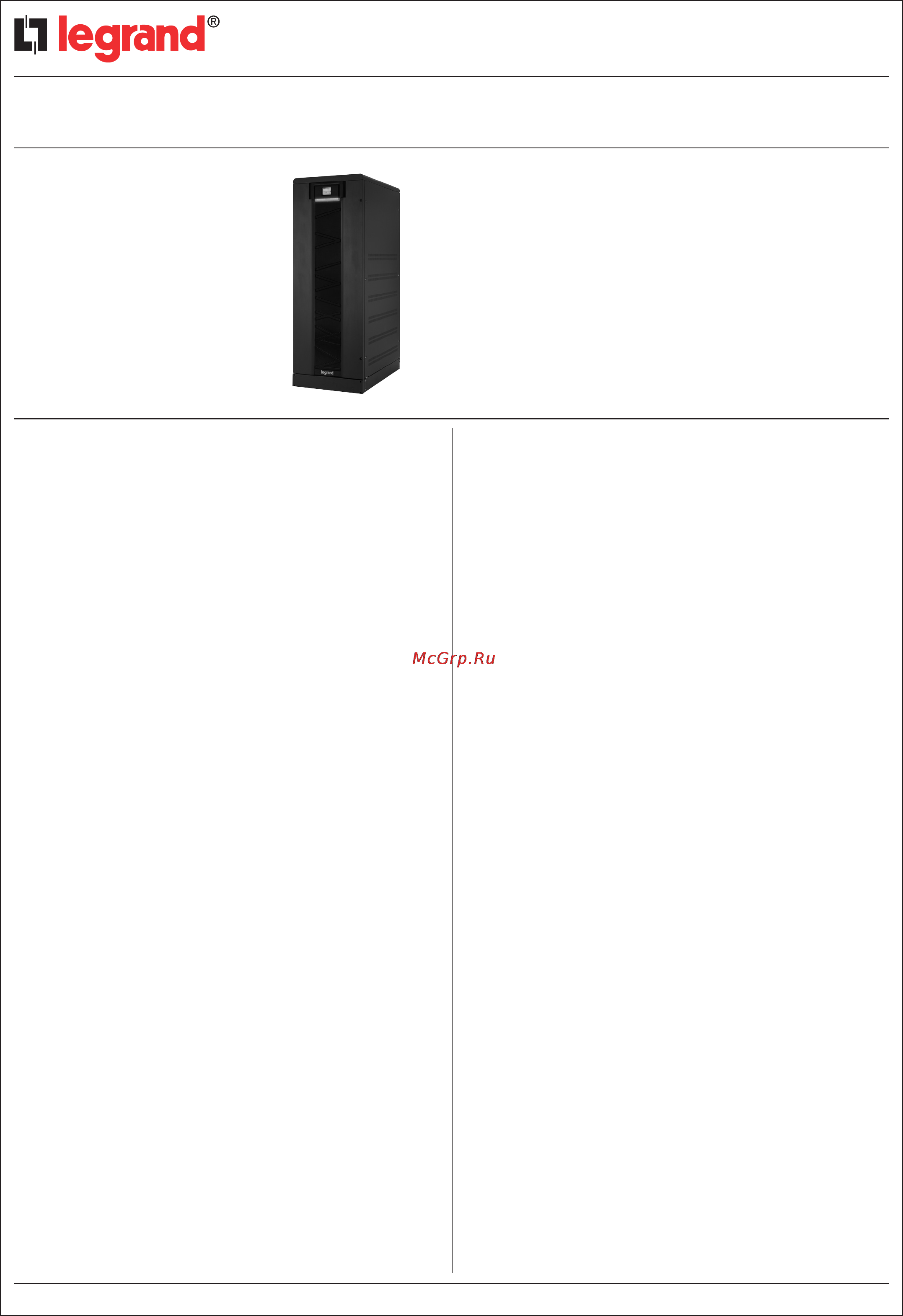
KEOR T 60 kVA
Legrand UPS model KEOR T 60 is an uninterruptible power source
with 3-Level IGBT switching technology, high frequency PWM
technology, Double Conversion On-line, solid neutral, with the
possibility to have N+X on site modular redundancy up to total 8
units, Rated Power 60 kVA–54 kW.
Batteries are lead acid, sealed, free maintenance, valve regulated,
and arranged, inside the UPS in dedicated Drawers or external
battery cabinet.
The architecture of this UPS is a Tower type. 1650h cabinet size
is available for internal battery configuration providing a minimum
uptime of 8 minutes at 70% of 0,9PF load.
It is possible to install up to 180pcs battery (7Ah or 9Ah) to 1650h
cabinet.
1.1 Architecture
Legrand UPS model KEOR T 60 has stand-alone architecture. UPS is
composed by following parts;
- IGBT Rectifier/PFC
- 3-Level IGBT Switching Technology
- Digital Signal Processor (DSP)
- 3.5” TFT Touch Panel
- Automatic Bypass
- Dual Input Bypass
- Internal Manual Bypass
- Standard Internal Backfeed Protection
- Internal Battery Drawer Shelves
The UPS can be easily configured on site, by the authorized
personnel, to operate in parallel. Also it is possible to arrange the
dual bypass by removing bridge connection on each input phase.
Legrand KEOR T 60 has 3-Level IGBT switching technology and
there is no transformer in the unit. These provide high efficiency for
the unit.
Backfeed protection provides additional protection at the input in the
event of bypass thyristors are short circuited.
By using internal backfeed contactor in bypass line provides safety
when fault situation occurs in static bypass line and prevents
upstream energy to the input.
The internal backfeed protection provides an easy on site installation
without any additive cabling or special MCCB type in the upstream
distribution panel.
1.2 Redundancy:
The Redundancy of the UPS allows N+X redundant configurations.
Up to 8 units of same size UPS can be connected in parallel.
1. GENERAL SPECIFICATIONS
1.3 By-pass
KEOR T has internal both static bypass and mechanical (maintenance)
bypass as standard. Addition to this input and bypass inputs can easily be
separated to obtain dual input by removing the bridge on the connector.
1.4 Control and Monitoring:
KEOR T is equipped with a touch screen graphic TFT display that
provides information, measurements, statuses and alarms of the
UPS in different languages. Below this display, there is a multicolour
LED bar showing status of UPS.
- GREEN: Normal or ECO Mode Operation
- ORANGE: Bypass or Battery Operation
- RED: Load not Supplied
A dedicated software of remote monitoring and management, installed
on a PC connected to the UPS, allows to check and set all working
parameters of KEOR T (the same functions available on the UPS
control panel) and, furthermore, to schedule and program computer
remote shutdown. Optional software (UPSMAN) or Net Interface card
(CS121 SK) allow the multi server shutdown and UPS remote control
on the LAN. Also, standard interface board comes with;
- RS232 Serial Communication Port
- Emergency Power Off (UPS OFF)
- Generator Contact (GEN ON)
- 4pcs programmable Dry Contact Information
- 2 contactor relays for Bypass and Battery
- ModBus (over RS485, with 2400 Baud Rate)
Standard Dry Contact Alarms are General Alarm, Bypass Active, Input
Failure and Synchronization OK. Addition to these; High Temperature,
Battery Test Failure, Output Failure alarms can be assigned to the
contacts. Each alarm can be assigned to separate contacts but also
one alarm may be assigned to all contacts.
KEOR T front panel is controlled by DSP microprocessor which works
together with DSP microprocessors in rectifier and inverter; by display
is possible to check all measurements, working parameters and status
of the system.
Here follow the measurements and working parameters available on
the display:
RECTIFIER (INPUT)
Voltage (Vac), per phase
Current (Aac), per phase
DC BUS Voltage (±Vdc)
Heatsink Temperature (°C)
FREQUENCY
Input Frequency (Hz)
Output Frequency (Hz)
BATTERY
Voltage (±Vdc)
Current (±Adc)
Temperature
Autonomy (minute)
INVERTER (OUTPUT)
Voltage (Vac), per phase
Current (Aac), per phase
Apparent Power (kVA), per
phase
Active Power (kW), per phase
Power Factor (load), per phase
Bypass Voltage, per phase
Load (%), per phase
Heatsink Temperature (°C)
Technical sheet: UPS-LGR-0081/GB 01/01/2014Last update: 01/01/2014
1/2
Содержание
- General specifications 1
- Index page 1
- Keor t 60 kva 1
- 01 2014 2
- 20 3 102 21 3 102 22 2
- Alarm voice enable disable key voice enable disable warning window enable disable 2
- Battery 2
- Battery string battery capacity 2
- Command menu 2
- Continue 2
- Display brightness 0 to 100 emergency power off nc no generator mode nc no modbus id time hh mm required for event log stamp date dd mm yyyy required for event log stamp language english 2
- General specifications 2
- Keor t 60 kva 2
- Legrand keor t displays up to 380 last events events are stored in eeprom using fifo method order number of last occurred event is 001 and the last event in the list is erased when there are 380 events 2
- Options 2
- Output 2
- Parallel mode 2
- Parallel mode enable disable single ups id redundancy 1 2 7 operation mode redundancy power increase 2
- Priority online inverter green bypass battery test keor t tests the battery automatically once each 90 days maintenance rectifier inverter bypass load supply yes no 2
- Relay 1 general alarm as standard can be adjusted from 7 different alarms relay 2 input failure as standard can be adjusted from 7 different alarms relay 3 battery failure as standard can be adjusted from 7 different alarms relay 4 output failure as standard can be adjusted from 7 different alarms 2
- Relay functions 2
- Technical sheet ups lgr 0081 gb last update 01 01 2014 2
- Technical specifications 2
- The ups allows also the following settings by display 2
- The ups keor t has the ce mark accordingly with the eu directives 73 23 93 68 89 336 92 31 93 68 and it complies with following standards en62040 1 generalrulesforelectricsafety en62040 2 electromagneticcompatibilityandimmunity emc en62040 3 performancesandtestingrules 2
- Voltage 380 400 415 frequency 50hz 60hz 2
Похожие устройства
- Legrand KEOR T 80 kVA Инструкция по эксплуатации
- Legrand Keor Т 100 kВA Инструкция по эксплуатации
- Legrand Keor Т 120 kВA Инструкция по эксплуатации
- Legrand Keor Т 10 kВA с разделительным трансформатором Инструкция по эксплуатации
- Legrand Keor Т 15 kВA с разделительным трансформатором Инструкция по эксплуатации
- Legrand Keor Т 20 kВA с разделительным трансформатором Инструкция по эксплуатации
- Legrand Keor Т 30 kВA с разделительным трансформатором Инструкция по эксплуатации
- Legrand Keor Т 40 kВA с разделительным трансформатором Инструкция по эксплуатации
- Legrand Keor Т 60 kВA с разделительным трансформатором Инструкция по эксплуатации
- Legrand Keor HP 100 kВA Инструкция по эксплуатации
- Legrand Keor HP 150 kВA Инструкция по эксплуатации
- Legrand Keor HP 200 kВA Инструкция по эксплуатации
- Legrand Keor HP 250 kВA Инструкция по эксплуатации
- Legrand Keor HP 300 kВA Инструкция по эксплуатации
- Legrand Keor HP 400 kВA Инструкция по эксплуатации
- Legrand Keor HP 500 kВA Инструкция по эксплуатации
- Legrand Keor HP 600 kВA Инструкция по эксплуатации
- Legrand Keor HP 800 kВA Инструкция по эксплуатации
- Canon EOS 650D Kit EF-S 18-135mm IS STM Black Инструкция по эксплуатации
- Canon EOS 5D Mark III Kit EF 24-105mm IS USM F4L Black Инструкция по эксплуатации