
Supermicro sys-5017r-mtf Инструкция по эксплуатации онлайн
Содержание
- Manual revision 1 release date februarty 15 2012 2
- Printed in the united states of america 2
- Warning handling of lead solder materials used in this product may expose you to lead a chemical known to the state of california to cause birth defects and other repro ductive harm 2
- About this manual 3
- Chapter 1 introduction 3
- Chapter 2 server installation 3
- Chapter 3 system interface 3
- Manual organization 3
- Preface 3
- Appendix a post error beep codes 4
- Appendix b uefi bios recovery instructions 4
- Appendix c system specifi cations 4
- Chapter 4 system safety 4
- Chapter 5 advanced serverboard setup 4
- Chapter 6 advanced chassis setup 4
- Chapter 7 bios 4
- Chapter 1 introduction 6
- Chapter 2 server installation 6
- Chapter 3 system interface 6
- Table of contents 6
- Chapter 4 system safety 7
- Chapter 5 advanced motherboard setup 7
- Appendix a post error beep codes 8
- Appendix b uefi bios recovery instructions 8
- Appendix c system specifi cations 8
- Chapter 6 advanced chassis setup 8
- Chapter 7 bios 8
- 1 overview 9
- Chapter 1 9
- Introduction 9
- 2 motherboard features 10
- I o ports 10
- Memory 10
- Processors 10
- Scu sata 10
- Serial ata 10
- 3 server chassis features 11
- Control panel 11
- Cooling system 11
- Intelligent power node manager nm 11
- Sata subsystem 11
- System power 11
- Ddriii 12
- Erver 5017r mtf 5017r mtrf user s manual 12
- Figure 1 1 intel c600 chipset system block diagram 12
- Note this is a general block diagram please see chapter 5 for details 12
- Pch patsburg ssb d 12
- 4 contacting supermicro 13
- Asia pacifi c 13
- Europe 13
- Headquarters 13
- 1 overview 15
- 2 unpacking the system 15
- 3 preparing for setup 15
- Chapter 2 15
- Choosing a setup location 15
- Server installation 15
- Rack precautions 16
- Server precautions 16
- Warnings and precautions 16
- Ambient operating temperature 17
- Circuit overloading 17
- Mechanical loading 17
- Rack mounting considerations 17
- Reduced airfl ow 17
- Reliable ground 17
- 4 installing the system into a rack 18
- Identifying the sections of the rack rails 18
- Installing the rear inner rails 18
- Installing the rack rails 19
- Installing the server into the rack 20
- Installing the server into a telco rack 21
- 1 overview 23
- 2 control panel buttons 23
- Chapter 3 23
- System interface 23
- 3 control panel leds 24
- Overheat fan fail 24
- 4 hard drive carrier leds 25
- 1 electrical safety precautions 27
- Chapter 4 27
- System safety 27
- 2 general safety precautions 28
- 3 esd precautions 29
- 4 operating precautions 30
- 1 handling the motherboard 31
- Advanced motherboard setup 31
- Chapter 5 31
- Precautions 31
- Unpacking 31
- 2 processor and heatsink installation 32
- Installing an lga2011 processor 32
- Installing a cpu heatsink 35
- 3 connecting cables 37
- Connecting data cables 37
- Connecting power cables 37
- Connecting the control panel 37
- 4 i o ports 38
- 5 installing memory 39
- Caution 39
- Memory population guidelines 40
- Chapter 5 advanced motherboard setup 41
- Recommended population balanced 41
- 6 adding pci cards 42
- 7 motherboard details 43
- Chapter 5 advanced motherboard setup 43
- Figure 5 4 super x9sri f layout 43
- For home or office use 43
- I sata0 43
- I sata1 43
- I sata2 i sata3 43
- I sata3 i sata2 43
- I sata4 43
- I sata5 43
- Jbt1 cmos clear see section 5 9 43
- Ji2c1 ji2c2 smb to pci e slots on enabled 43
- Jpb1 bmc enable pins 1 2 enabled 43
- Jpbios1 bios recovery pins 1 2 normal 43
- Jpg1 onboard vga enable pins 1 2 enabled 43
- Jpl1 jpl2 lan1 lan2 enable pins 1 2 enabled 43
- Jpme1 intel me mode select pins 1 2 normal 43
- Jpusb1 usb power select pins 2 3 dual power 43
- Jstby1 wake on lan enable pins 2 3 enabled 43
- Jumper description default 43
- Jwd1 watch dog reset pins 1 2 reset 43
- Lan1 lan2 43
- P1 dimm1a 43
- P1 dimm1b 43
- P1 dimm2a 43
- P1 dimm2b 43
- P1 dimm3a 43
- P1 dimm3b 43
- P1 dimm4a p1 dimm4b 43
- Rev 1 1 43
- Slot4 pci e 3 x8 in x16 43
- Slot5 pci e 2 x4 in x16 43
- Slot6 pci e 3 x16 43
- Tested to comply 43
- With fcc standards 43
- X9sri f quick reference 43
- Connector description 44
- Led description color state status 44
- 8 connector defi nitions 45
- Chapter 5 advanced motherboard setup 45
- For pin defi nitions 45
- Hdd led 45
- Header is located on pins 19 and 20 45
- Nmi button 45
- Of jf1 refer to the table on the right 45
- Pin processor pwr 24 pin main pwr 45
- Pins 15 and 16 of jf1 refer to the table on the right for pin defi nitions 45
- Power connectors 45
- Power led 45
- The 24 pin main power connector jpw1 is used to provide power to the motherboard the 8 pin cpu pwr connector jpw2 is also required for the processor these power connectors meet the ssi eps 12v specifi cation see the tables on the right for pin defi nitions 45
- The hdd led connections are located on pins 13 and 14 of jf1 attach a cable here to indicate hdd activity see the table on 45
- The non maskable interrupt button 45
- The power led connection is located on 45
- The right for pin defi nitions 45
- And 8 of jf1 to display uid unit id sig 46
- And oh fan fail connections on pins 7 46
- Case refer to the table on the right for 46
- Chassis overheat fan failure refer to the 46
- Connect an led cable to the front uid 46
- Erver 5017r mtf 5017r mtrf user s manual 46
- Nals or to provide advanced warnings for 46
- Nic1 nic2 lan1 lan2 46
- On pins 5 and 6 of jf1 refer to the table on the right for pin defi nitions 46
- Overheat oh fan fail front uid led 46
- Pin defi nitions 46
- Power fail led 46
- Reset button 46
- Table on the right for pin defi nitions 46
- The nic network interface controller led connection for lan port 1 is located on pins 11 and 12 of jf1 and the led connection for lan port 2 is on pins 9 and 10 nic1 led and nic2 led are 2 pin nic led headers attach nic led cables to nic1 led and nic2 led to display network activities for lan 1 and lan2 refer to the table on the right for pin defi nitions 46
- The power fail led connection is located 46
- The reset button connection is located on pins 3 and 4 of jf1 attach it to a the hardware reset button on the computer 46
- A usb connector usb cables are not 47
- Additional six usb ports in three head 47
- Are located on the i o backpanel and an 47
- Back chassis access usb 11 is a type 47
- Chapter 5 advanced motherboard setup 47
- Ers usb2 3 4 5 12 13 provide front 47
- Included see the tables on the right for 47
- On the the motherboard see the table on the right for pin defi nitions 47
- Pin defi nitions 47
- Power button 47
- Serial ports 47
- The com1 port is located on the i o backpanel com2 is a header located 47
- The power button connection is located on pins 1 and 2 of jf1 momentarily contacting both pins will power on off the system this button can also be confi g ured to function as a suspend button see bios setup to turn off the power in the suspend mode press the button for at least 4 seconds refer to the table on the right for pin defi nitions 47
- Two universal serial bus ports usb 0 1 47
- Universal serial bus usb 47
- A chassis intrusion header is located at 48
- Atx ps 2 keyboard and ps 2 mouse ports 48
- Cable to pins 1 4 see the table on the right for pin defi nitions 48
- Chassis intrusion 48
- Defi nitions 48
- Erver 5017r mtf 5017r mtrf user s manual 48
- Fan headers 48
- Jl1 on the motherboard attach the ap 48
- Mouse ports are located beside the usb ports see the table on the right for pin 48
- Note please use all 3 pin fans or all 4 pin fans on a motherboard do not mix 3 pin fans and 4 pin fans on the same board 48
- On the jd1 header pins 6 7 are used for the internal speaker close pins 6 7 with a jumper or cap to use the onboard 48
- Propriate cable from the chassis to inform 48
- Sis is opened 48
- Speaker if you wish to use an external speaker attach the external speaker s 48
- Speaker jd1 48
- The atx ps 2 keyboard and the ps 2 48
- The x9sri f has fi ve fan headers fan1 fan4 and fana these are all 4 pin fan headers however pins 1 3 are backward compatible with traditional 3 pin fans a fan speed control setting in the bios hardware monitoring section allows the bios to automatically set fan speeds based on the system temperature refer to the table on the right for pin defi nitions 48
- You of a chassis intrusion when the chas 48
- A system management bus header for 49
- C connector 49
- C connector is 49
- C on the motherboard 49
- Chapter 5 advanced motherboard setup 49
- Located at jp 49
- Nect the appropriate cable here to use 49
- Power supply 49
- Power supply fan and system tempera ture see the table on the right for pin defi nitions 49
- System management bus jipmb 49
- The ipmb i2c connection on your system 49
- The ipmi slot is located at ipmb con 49
- The power supply 49
- The wake on lan header is located at jstby1 on the motherboard see the table on the right for pin defi nitions 49
- This connector monitors the status of the 49
- This header is used to connect a trusted platform module tpm available sepa rately from a third party vendor a tpm is a security device that allows encryption and authentication of hard drives disal lowing access if the tpm associated with it is not installed in the system see the table on the right for pin defi nitions 49
- Trusted platform module header 49
- Use this feature 49
- Wake on lan 49
- You must also have a lan card with a wake on lan connector and cable to 49
- Dom pwr connector 50
- Erver 5017r mtf 5017r mtrf user s manual 50
- Gen1 gen power to a solid state dom 50
- Nector located at jsd1 provides 5v 50
- Off uid led and the front uid led this provides easy identifi cation of a system 50
- Pin defi nitions 50
- Sata ports see the table on the right for 50
- Storage device connected to one of the 50
- T sgpio 1 2 3 sgpio 1 2 headers 50
- The disk on module dom power con 50
- The rear uid switch the blue backpanel uid led and front uid led will turn on push the rear uid switch again to turn 50
- The rear uid switch the rear uid led and front uid led on jf1 are designed 50
- To work together when the user pushes 50
- Two t sgpio serial link general pur pose input output headers are located next to the i sata ports on the mother board additionally two 3 sgpio ports are also located next to jusb 8 9 these headers are used to communicate with the enclosure management chip in the system see the table on the right for pin defi nitions 50
- Unit id switch uid sw 50
- Unit that may be in need of service 50
- Beep codes see the table on the right 51
- Chapter 5 advanced motherboard setup 51
- For pin defi nitions 51
- Internal buzzer sp1 51
- Overheat fan fail led joh 51
- The internal buzzer sp1 can be used 51
- The joh1 header is used to connect an led to provide warnings of chassis over heat this led will also blink to indicate a fan failure refer to the table on right for pin defi nitions 51
- To provide audible indications for various 51
- 9 jumper settings 52
- 10 onboard indicators 54
- 11 sata ports 55
- Chapter 5 advanced motherboard setup 55
- Sata ports 55
- Ten serial ata sata ports i sata 0 5 and s sata 1 4 are included on the motherboard see the table on the right for pin defi nitions for the onboard sata ports 55
- 12 installing drivers 56
- Superdoctor iii 57
- 1 static sensitive devices 59
- Advanced chassis setup 59
- Chapter 6 59
- Precautions 59
- Unpacking 59
- 2 control panel 60
- Erver 5017r mtf 5017r mtrf user s manual 60
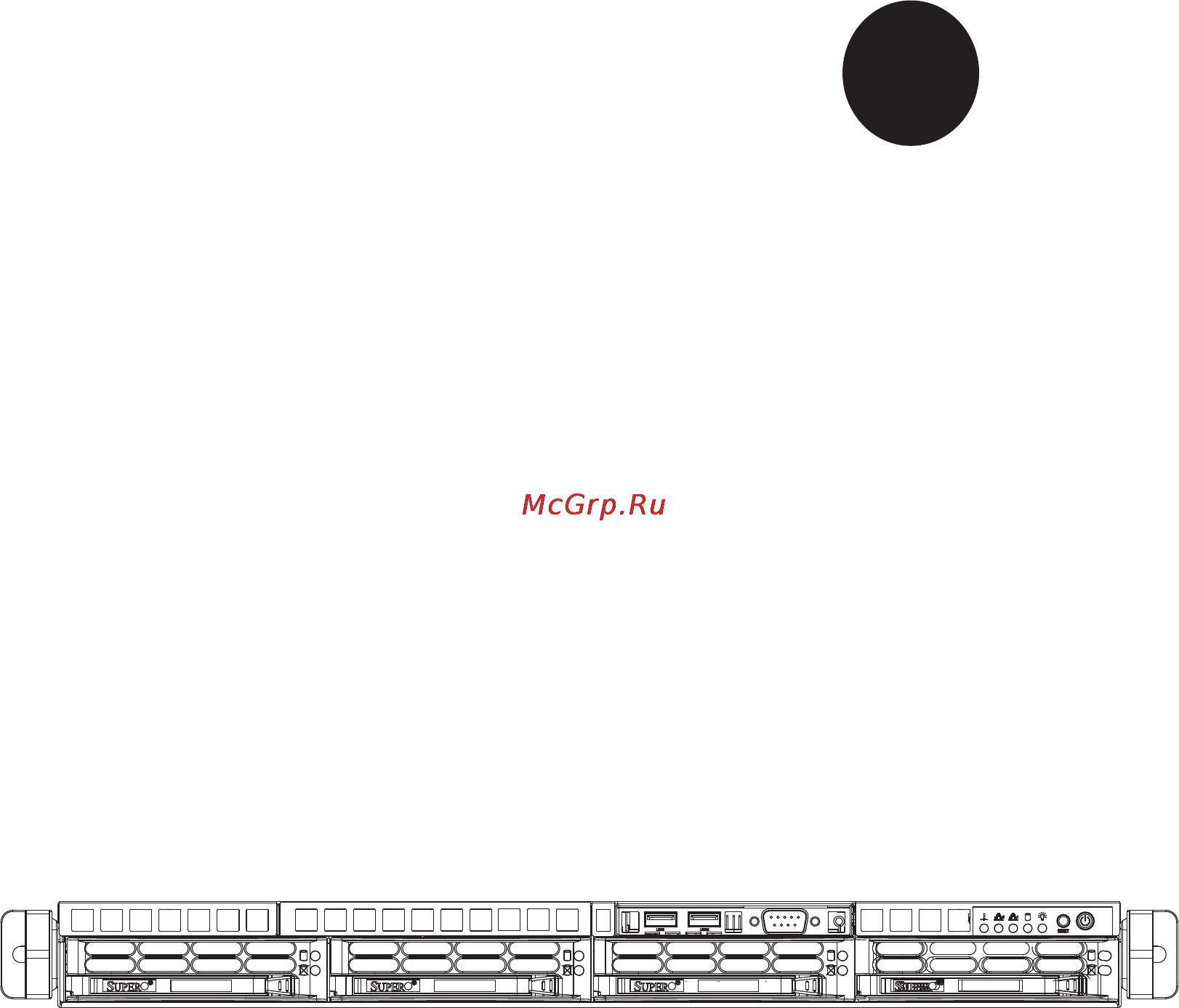
- Figure 6 1 chassis front view 60
- Figure 6 2 chassis rear view 60
- Status indicators these wires have been bundled together in a ribbon cable to simplify the connection 60
- The 5017r mtrf includes two power supplies for redundancy 60
- The control panel buttons details on jf1 can be found in chapter 5 60
- The control panel located on the front of the chassis must be connected to the jf1 connector on the serverboard to provide you with system control buttons and 60
- The leds inform you of system status see chapter 3 for details on the leds and 60
- 3 accessing the inside of the system 61
- 4 system fans 62
- 5 drive bay installation removal 62
- Removing the front bezel 62
- System fan failure 62
- Accessing the drive bays 63
- Hard drive installation 63
- Sata backplane 64
- Dvd rom drive installation 65
- 6 power supply 66
- Power supply failure 66
- R mtf power 66
- R mtrf power 67
- 1 introduction 69
- Chapter 7 69
- How to change the confi guration data 69
- Starting bios setup utility 69
- 2 main setup 70
- How to start the setup utility 70
- 3 advanced setup confi gurations 72
- Boot feature 72
- Processor clock options 73
- Chipset confi guration 76
- Ide sata confi guration 79
- Pcie pci pnp confi guration 81
- Super io device confi guration 82
- Remote access confi guration 83
- Hardware health confi guration 84
- Acpi confi guration 85
- Me subsystem 86
- Network stack 86
- 4 event logs 87
- 5 ipmi 88
- 6 iscsi 90
- 7 boot settings 91
- 8 security settings 92
- 9 exit options 93
- 10 main confi guration page 94
- Port confi guration menu 94
- Appendix a 97
- Post error beep codes 97
- Appendix b 99
- B 1 an overview to the uefi bios 99
- B 2 how to recover the uefi bios image the main bios block 99
- B 3 to recover the main bios block using a usb attached device 99
- Uefi bios recovery instructions 99
- After locating the new bios binary image the system will enter the bios 100
- Aptio setup utility copyright c 2011 american megatrends inc 100
- Decide to proceed with bios recovery follow the procedures below 100
- Erver 5017r mtf 5017r mtrf user s manual 100
- Insert the usb device that contains the new bios image super rom into your usb drive and power on the system 100
- Key you will see the progress of bios recovery as shown in the screen below 100
- May take from a few seconds to one minute 100
- Note at this point you may decide if you want to start with bios recovery if you 100
- Note do not interrupt the process of bios fl ashing until it is completed 100
- Note if you cannot locate the super rom fi le in your driver disk visit our website at www supermicro com to download the bios image into a usb fl ash device and rename it to super rom for bios recovery use 100
- Recovery page as shown below 100
- Simultane ously on your ps2 or usb keyboard until your hear two short beeps this 100
- To perform uefi bios recovery using a usb attached device follow the instruc tions below 100
- Using a different machine copy the super rom binary image fi le into the disc root directory of a usb device or a writeable cd dvd 100
- Version 2 2 211 copyright c 2011 american megatrends inc 100
- Warning bios recovery mode has been detected 100
- When the screen as shown above displays using the arrow key select the 100
- After the process of bios recovery is complete press any key to reboot the 101
- Appendix b uefi bios recovery 101
- Aptio setup utility copyright c 2011 american megatrends inc 101
- Note do not interrupt this process until bios fl ashing is completed 101
- System 101
- Using a different system extract the bios package into a bootable usb fl ash drive 101
- Version 2 2 211 copyright c 2011 american megatrends inc 101
- Warning system firmware is being updated 101
- When a dos prompt appears type ami bat biosname at the prompt 101
- Appendix c 103
- Chipset 103
- Expansion slots 103
- Memory capacity 103
- Processors 103
- Sata drive bays 103
- Serverboard 103
- System specifi cations 103
- Chassis 104
- Operating environment 104
- Power supply 104
- System cooling 104
- System input requirements 104
- Weight 104
- Regulatory compliance 105
Похожие устройства
- Sven ic-320 Инструкция по эксплуатации
- Sven ap-b770mv Инструкция по эксплуатации
- Sven ap-970mv Инструкция по эксплуатации
- Sven ap-940mv Инструкция по эксплуатации
- Sven ap-680mv Инструкция по эксплуатации
- Sven ap-600 Инструкция по эксплуатации
- Sven ht-200 Инструкция по эксплуатации
- Starline a64 Инструкция по эксплуатации
- Starline m21 Инструкция по эксплуатации
- Starline b94 Инструкция по эксплуатации
- Starline m17+ Инструкция по эксплуатации
- Starline i95 eco Инструкция по эксплуатации
- Starline d10 Инструкция по эксплуатации
- Starline i93 Инструкция по эксплуатации
- Starline m15 эко Инструкция по эксплуатации
- Starline m15 эко+ Инструкция по эксплуатации
- Sven rx-112 black usb Инструкция по эксплуатации
- Sven rx-150 usb+ps/2 black Инструкция по эксплуатации
- Sven avr pro lcd 10000 Инструкция по эксплуатации
- Sven avr pro 5000 Инструкция по эксплуатации