
Moxa ICS-G7848-HV-HV Руководство по аппаратной части онлайн
– 1 – – 2 – – 3 – - 4 -
P/N: 1802077480011
ICS-G7748/G7750/G7752/G7848
/G7850/G7852 Series
Hardware Installation Guide
Second Edition, September 2011
Package Checklist
The Moxa ICS-G7748/G7750/G7752/G7848/G7850/G7852 Series
industrial rackmount switches are shipped with the following items.
If any of these items are missing or damaged, please contact your
customer service representative for assistance.
• ICS-G7748/G7750/G7752/G7848/G7850/G7852 switch
• RJ45 to DB9 console port cable
• 2 power cords
• 2 PWR-G7000-AC power modules
• Protective caps for unused ports
• 2 rackmount ears
• Documentation and software CD
• Hardware installation guide (printed)
• Warranty card
• 2 metal handles
• 12 cover plates
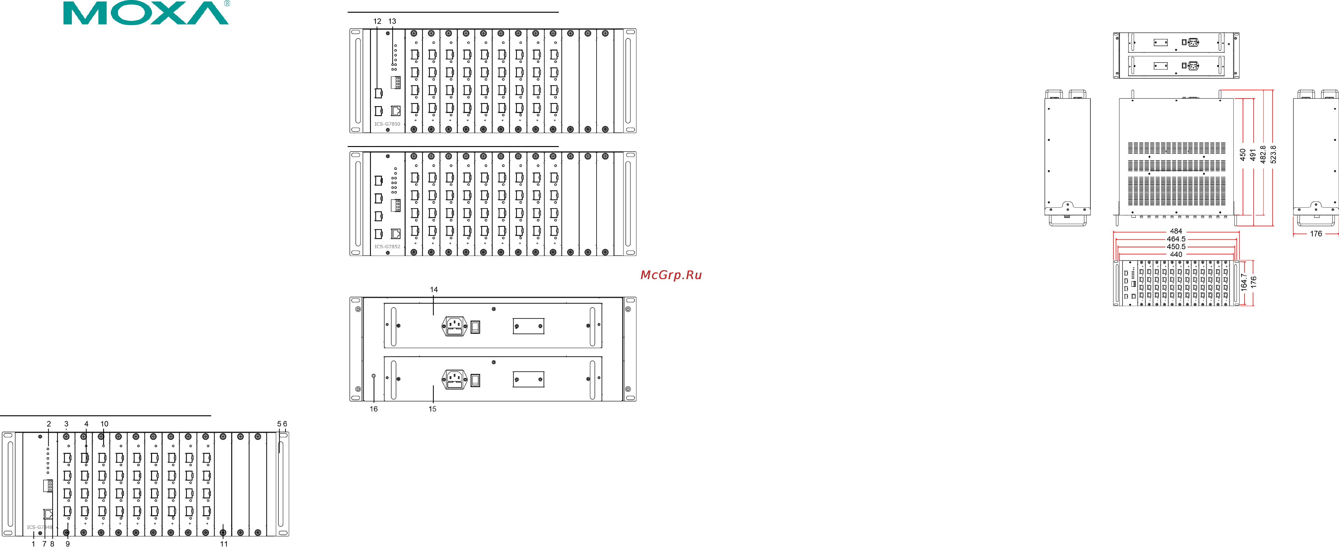
Panel Layouts
Front View
ICS-G7748/G7848 with IM-G7000 modules
ICS-G7750/G7850 with IM-G7000 modules
ICS-G7752/G7852 with IM-G7000 modules
Rear View
1. Main module
2. System status LEDs
3. Copper module slot for 10/100/1000 BaseT(X) port or SFP
module slot for 100/1000Base SFP
4. 10/100/1000 BaseT(X) port status LEDs or 100/1000Base SFP
port status LEDs
5. Metal handle
6. 19” rack-mount ear
7. Serial Console port
8. Terminal block for Relay Output, Digital Input
9. Hot-swap button
10. Hot-swap status LED
11. Metal cover plate
12. 10 Gigabit Ethernet SFP+ slot
13. 10 Gigabit Ethernet SFP+ port status LEDs
14. First PWR-G7000-AC power module (PWR1)
15. Second PWR-G7000-AC power module (PWR2)
16. Grounding screw
Grounding the Industrial Rackmount Switch
Grounding and wire routing help limit the effect of noise from
electromagnetic interference (EMI). Run the ground connection from
the ground screw to the grounding surface prior to connecting
devices.
Connecting the Power Inputs
The ICS-G7748/G7750/G7752/G7848/G7850/G7852 supports dual
redundant power supplies: Power Supply 1 (PWR1) and Power
Supply 2 (PWR2). The connections for PWR1 and PWR2 are located
on the rear side (shown below). Be sure to use a standard power
cord with an IEC C13 connector, which is compatible with the AC
power inlet.
Installing/Removing ICS Switch Modules
IM-G7000 Series modules are designed for installation in
ICS-G7748/G7750/G7752/G7848/G7850/G7852 Series switches.
To insert the module into the slot, first remove the cover first. Be
sure to push the module on the track and firmly connect the module
with the connector. Finally, ensure stability and secure the module
by firmly tightening the screws.
IM-G7000 Series modules are hot-swappable modules. To remove
modules from a switch, follow these steps:
1. Push the Hot-Swap button on the module
2. Wait for the HOT SWAP STATE LED to turn off.
3. Loosen the screw and remove the module
Dimensions (unit = mm)
Содержание
- Connecting the power inputs 1
- Dimensions unit mm 1
- Front view 1
- G7850 g7852 series 1
- Grounding the industrial rackmount switch 1
- Hardware installation guide 1
- Ics g7748 g7750 g7752 g7848 1
- Installing removing ics switch modules 1
- Package checklist 1
- Panel layouts 1
- Rear view 1
- Second edition september 2011 1
- Rack mounting instructions 2
- Restricted access locations 2
- Specifications 2
Похожие устройства
- Moxa ICS-G7848-HV-HV Руководство по использованию командной строки
- Moxa ICS-G7848-HV-HV Руководство по созданию резервированных сетей
- Moxa ICS-G7848-HV-HV Технические характеристики
- Moxa ICS-G7850-2XG-HV-HV Инструкция по эксплуатации
- Moxa ICS-G7850-2XG-HV-HV Руководство по аппаратной части
- Moxa ICS-G7850-2XG-HV-HV Руководство по использованию командной строки
- Moxa ICS-G7850-2XG-HV-HV Руководство по созданию резервированных сетей
- Moxa ICS-G7850-2XG-HV-HV Технические характеристики
- Moxa ICS-G7852-4XG-HV-HV Инструкция по эксплуатации
- Moxa ICS-G7852-4XG-HV-HV Руководство по аппаратной части
- Moxa ICS-G7852-4XG-HV-HV Руководство по созданию резервированных сетей
- Moxa ICS-G7852-4XG-HV-HV Руководство по использованию командной строки
- Moxa ICS-G7852-4XG-HV-HV Технические характеристики
- Moxa IM-G7000-4GTX Инструкция по эксплуатации
- Moxa IM-G7000-4GSFP Инструкция по эксплуатации
- Moxa IM-G7000A-4PoE Инструкция по эксплуатации
- Moxa IM-G7000A-4GTX Инструкция по эксплуатации
- Moxa IM-G7000A-4GSFP Инструкция по эксплуатации
- Moxa EDS-608 Инструкция по эксплуатации
- Moxa EDS-608 Руководство пользователя Англ.