
Fluke 707 ex 707Ex CCD _ Контрольные схемы онлайн
Fluke 707Ex mA Calibrator
NI/I/2/A-D Ta = -10 ˚C … +50 ºC
Intrinsically outputs for Class I, Div. 1, Groups A, B, C, & D
Input Entity Parameters: Ui = 30 V, Ii = 250 mA, Ci = 10 nF, Li = 0
Output Entity Parameters: Uo (Voc) = 27.6 Volts, Io (Isc) = 96.9 mA, Po = 0.7 W,
Co (Ca) = 76 nF, Lo (La) = 2.5 mH
Nonincendive outputs for Class I, Div. 2, Groups A, B, C, & D
Input Nonincendive Parameters: Vmax = 30 V, Ci = 10 nF, Li = 0
Outpu t Nonincendive Parameters: V oc = 27.6 Volts, Isc = 26.4 mA, Ca = 200 nF, La = 86 mH
SHEE T 1 of 1
SCALE: None
Fluke 707Ex
CCD
Date 13.11.2002
By: Bergmeier
Control Drawing
ONLY CONNECTIONS SPECIFIED ON THIS DRAWING ARE ALLOWED.
OTHER CONNECTIONS MAY INVALIDATE INTRINSIC SAFETY.
DO NOT USE THE FLUKE 707Ex IN DIVISION 1 LOCATIONS!
Rev Description By Date
Fluke 707Ex may be connected to an existing
Intrinsically Safe l oop
when connected per notes 4-9
Measure mA:
(-)
(+)
Fluke 707Ex
(+)
(-)
Approved Ass ociate Apparatus
Source
(-)
(+)
Simple Apparatus
or
Approved Intrinsically Safe Apparatus
Fluke 707Ex may be connected to an existing
Intrinsically Safe l oop
when connected per notes 4-9
Source Mode:
(-)
(+)
Fluke 707Ex
(+)
(-)
Simple Apparatus
or
Approved Intrinsically Safe Apparatus
Source
(+)
(-)
Simple Apparatus
or
Approved Intrinsically Safe Apparatus
Fluke 707Ex may be connected to an existing loop
provided the loop is not opened
and when connected per notes 4-9
Measure V:
(-)
(+)
Fluke 707Ex
(+)
(-)
Approved Ass ociate Apparatus
Source
(-)
(+)
Simple Apparatus
or
Approved I ntrinsically safe Apparatu s
Fluke 707Ex. mA Calibrat or may be connected to:
Any Simple Apparatus or Int rins ically S afe
Apparatus. when connected per notes 4-9
Associat ed Apparatus. when connected
per notes 4-9
(-)
(+)
Fluke 707Ex
(+)
(-)
Simple Apparatus
Approved Intrinsically Safe Apparatus
Approved Ass ociate Apparatus
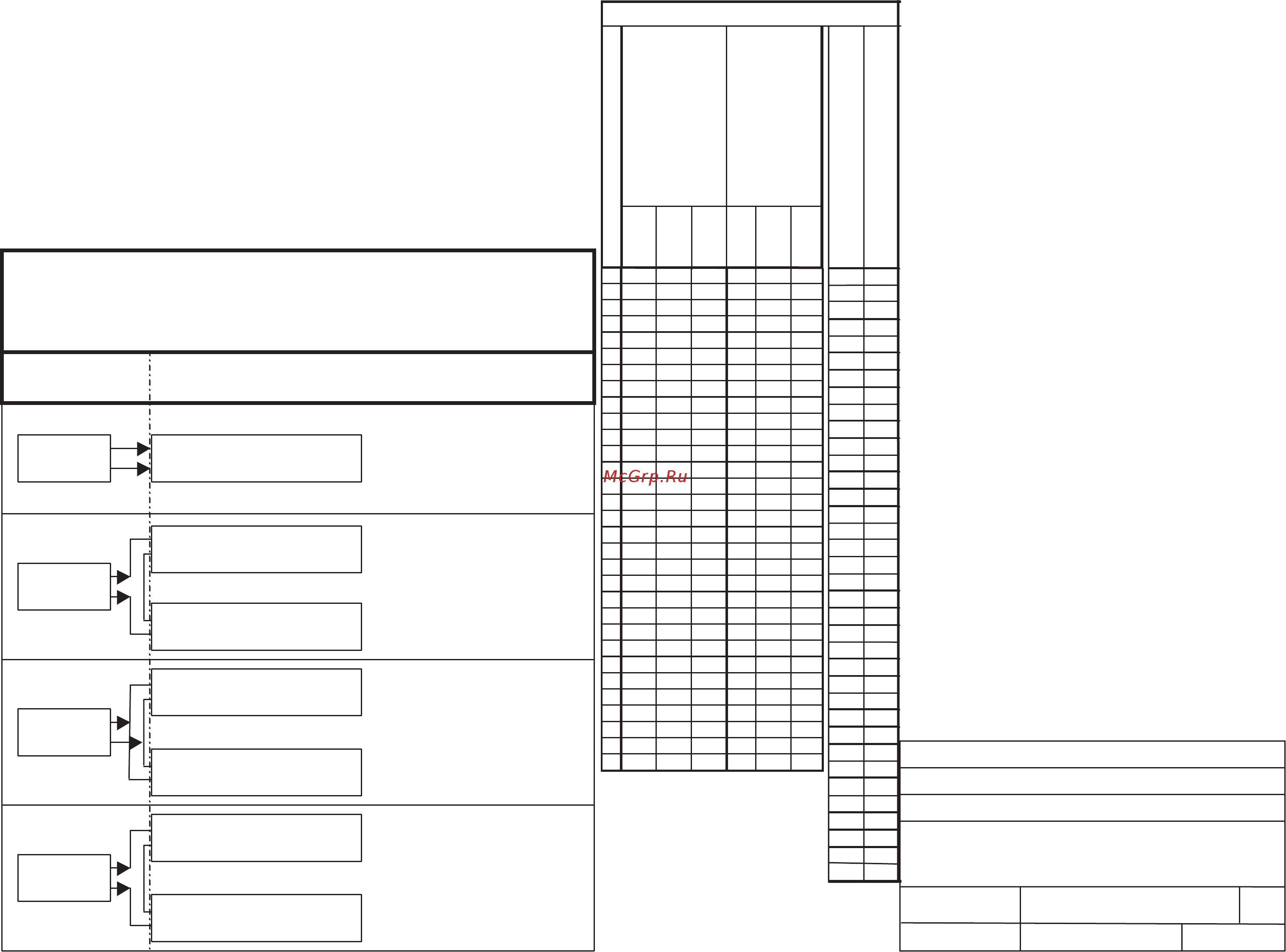
All Modes:
Unclassified area or
Class I, Div 2, Groups A – D
see note 2
Class I, Division 1, Groups A – D or
Class I, Division 2, Groups A – D
Vt(loop) Total Voltage Loop in Volts
Group A/B
Group C
Group D
It(loop) Total L oop Cu rrent in / mA
Maximum allowed loop inductance Lt(loop) in mH
based upon It (loop)
51000
6860
8520
10 33 0
12 25 0
14 18 0
16 13 5
18 11 0
20 88
22 74
24 62
26 50
28 47
30 39
32 37
34 33
36 28 .5
38 26
40 24
44 20
48 16 .5
52 14 .5
56 10
60 9
64 8.8
68 8
72 7.2
76 6.6
80 6
84 5.3
88 4.85
92 4.6
96 4.2
10 0 3.9
10 4 3.65
11 0 3.4
Table 1. Allowed Maximum Values
28 147.5 367.6 486.9 83.0 650 2150
29 135.2 336.9 451.2 74.0 605 1970
30 124.2 311.1 418.0 66.0 560 1820
31 114.7 286.5 389.8 60.5 515.0 1670
32 108.0 265.6 362.7 56.0 475 1560
33 101.7 247.1 339.3 51.5 437 1460
34 95.9 229.9 318.4 48.0 406 1370
35 90.7 217.6 301.2 45.0 387 1280
36 85.9 206.6 285.2 42.0 370 1200
37 81.4 196.7 270.5 39.0 353 1120
38 77.3 188.1 257.0 36.4 336 1060
39 73.5 179.5 244.7 34.2 320 1000
40 70.1 170.9 233.6 32.5 305 940
41 66.8 163.5 222.5 31.0 290 890
42 63.7 157.4 212.7 29.7 275 850
43 60.9 150.0 202.9 28.4 262 810
44 58.3 143.9 194.3 27.1 250 770
45 55.7 138.9 185.7 25.9 240 730
46 54.1 134.3 179.7 24.7 230 690
47 52.5 129.8 173.7 23.5 220 650
48 50.8 125.2 167.7 22.3 210 620
49 49.2 120.6 161.7 21.1 201 594
50 47.5 115.6 155.7 20.0 193 570
51 46.4 112.3 151.6 19.0 187 547
52 45.3 109.0 147.5 18.3 181 524
53 44.2 105.7 143.4 17.4 175 501
54 43.0 102.5 139.3 16.8 170 479
55 41.9 99.2 135.2 16.5 166 457
56 40.8 95.9 131.1 15.5 159.5 434
57 39.7 92.6 127.0 14.8 154 411
58 38.5 89.3 123.0 14.1 148.5 389
Group A/B
Group C
Group D
Maximum
allowed loop
Capacitance,
Ct(loop) in nF,
based upon
Vt (lo op )
Maximum
allowed loop
Curren t, in mA
It(loop), based
upon Vt(loop)
mA nF
NOTES:
1. The Fluke 707Ex Calibrator must not be used in Division 1 Hazardous (Classified) Locations.
NOTE
The Fluke 707Ex Calibrator cannot be installed using standard NEC Division 2 wiring
practices. Note 2 must be adhered to.
2. The Fluke 707Ex Ca
librator can only be used Division 2 Hazardous (Classified) Location provide
the following conditions are satisfied.
a.
The area is free of Flammable Vapors OR
b.
The connections are to a device(s) with nonincendive field wiring parameters (see notes
5 & 6) OR
c.
The connections are to a device(s) with Intrinsic Safety (see notes 4 & 6)
.
3.
Connections to an Intrinsically safe Apparatus/Associated Apparatus/Loop
must meet the requirements of notes 4, 6, & 7
Connections to an Nonincendive wiring Apparatus/Associated Apparatus/Loop
must meet the requirements of notes 5, 6, & 7
4. Intrinsic Safety Entity concept:
The Intrinsic Safety Entity concept allows the interconnection of devices with entity parameters:
Uo or Voc or Vt ≤ Vmax or Ui. Io or Isc or It ≤ Imax or Ii.
Ca or Co ≥ Ci + Ccable. La or Lo ≥ Li + Lcable. Po ≤ Pi.
Uo or Voc or Vt of Associated Apparatus ≤ Ui of Fluke 707 Ex Calibrator.
Uo (Voc) of Fluke 707 Ex mA Calibrator ≤ Vmax or Ui of Intrinsically Safe Apparatus and
≤ Uo or Voc or Vt of Associated Apparatus
Io (Isc) of Associated Apparatus ≤ Ii of Fluke 707Ex
Notes for Fluke 707Ex connected to Associated Apparatus
Vt(loop) = Vo(707Ex) + Voc or Vt of Associated Apparatus.
It(loop) = Io(707Ex) + Isc or It of Associated A
pparatus.
Pt(loop) = Po(707Ex) + Po of Associated Apparatus
Vt(loop) ≤ Ui of Intrinsically Safe Apparatus.
It(loop) ≤ Ii of Intrinsically Safe Apparatus.
Pt(loop) ≤ Pi of Intrinsically Safe Apparatus.
Uo (Voc) of Fluke 707 Ex Calibrator ≤ Vmax or Ui of Intrinsically Safe Apparatus.
Ct(loop) = Co(707Ex) + Co of Associated Apparatus + Ci of Intrinsically Safe Apparatus + Ccable
Lt(loop) = Lo(707Ex) + Lo of Associated Apparatus + Li of Intrinsically Safe Apparatus + Lcable
It(loop) ≤ Itable for calculated Vt(loop)
Ct(loop) ≤ Ctable for calculated Vt(loop)
Lt(loop)
≤
Ltable for calculated It(loop) calculated Vt(loop)
5. Nonincendive wiring concept:
The Nonincendive wiring concept allows the interconnection of devices with
Nonincendive wiring parameters:
Voc or Vt ≤ Vmax
Ca or Co ≥ Ci + Ccable
La or Lo ≥ Li + Lcable.
Voc or Vt of Associated Nonincendive Field Wiring Apparatus
≤ Vmax of Fluke 707 Ex Calibrator.
Voc of Fluke 707 Ex Calibrator ≤ Vmax of Nonincendive Field Wiring Apparatus
and ≤ Voc or Vt of associated nonincendive field wiring Apparatus
Notes for Fluke 707Ex connected to associated nonincendive field wiring Apparatus (NI)
Vt(loop) = Voc(707Ex) + Voc or Vt of Associated Nonincendive Field Wiring Apparatus.
It(loop) = Isc (707Ex) + Isc or It of Associated Nonincendive Field Wiring Apparatus.
Vt(loop) ≤ Vmax of Nonincendive Field Wiring Apparatus.
Voc of Fluke 707 Ex Calibrator ≤ Vmax of Nonincendive Field Wiring Apparatus.
Ct(loop) = Ca(707Ex) + Ca of Associated Nonincendive Field Wiring Apparatus
+ Ci of Nonincendive Field Wiring Apparatus + Ccable
Lt(loop) = La(707Ex) + La of Associated Nonincendive Field Wiring Apparatus
+ Li of Nonincendive Field Wiring Apparatus + Lcable
It(loop) ≤ Itable for calculated Vt(loop)
Ct(loop) ≤ Ctable for calculated Vt(loop)
Lt(loop) ≤ Ltable for calculated It(loop) calculated Vt(loop)
6. Installation must be in accordance with Article 500 of the NEC® (ANSI/NFPA 70)
and ANSI/ISA RP12.6
7. The Fluke 707Ex Calibrator may only be connected to loop terminals and must not be connected to
internal circuitry of Associated Apparatus or Intrinsically Safe Apparatus. Connection to internal
circuitry of Associated Apparatus or internal circuitry of Intrinsically Safe Apparatus violates Approval.
8. Applying more than 28 volts to the input terminals invalidates the Calibrator’s Ex- Approval and results
in permanent damage to the unit so it can no longer be used.
9. Refer to the 707Ex Users Manual (provided on the CD) for additional Safety Information
10.
No revision to this drawing is permitted without FM approval
x
PN 2053993 Rev. 2
W
W
Содержание
- Any simple apparatus or intrinsically safe apparatus when connected per notes 4 9 1
- Approved associate apparatus source 1
- Associated apparatus when connected per notes 4 9 1
- Class i division 1 groups a d or class i division 2 groups a d 1
- Control drawing 1
- Fluke 707ex 1
- Fluke 707ex ccd 1
- Fluke 707ex ma calibrator may be connected to 1
- Fluke 707ex may be connected to an existing intrinsically safe loop when connected per notes 4 9 1
- Fluke 707ex may be connected to an existing loop provided the loop is not opened and when connected per notes 4 9 1
- Group a b 1
- Group c 1
- Group d group d 1
- It loop total loop current in ma 1
- Maximum allowed loop capacitance ct loop in nf based upon vt loop 1
- Maximum allowed loop current in ma it loop based upon vt loop 1
- Maximum allowed loop inductance lt loop in mh based upon it loop 1
- Simple apparatus approved intrinsically safe apparatus approved associate apparatus 1
- Simple apparatus or approved intrinsically safe apparatus 1
- Simple apparatus or approved intrinsically safe apparatus source 1
- Table 1 allowed maximum values 1
- Unclassified area or class i div 2 groups a d see note 2 1
- Vt loop total voltage loop in volts 1
Похожие устройства
- Fluke 707 ex Дополнение к информации о калибровке
- Fluke 707 ex Информация о калибровке
- Fluke 707 ex Приложение к паспорту безопасности
- Fluke 707 ex Паспорт безопасности
- Fluke 707 ex Приложение к Руководству по эксплуатации
- Fluke 705 Дополнение к информации о калибровке
- Fluke 705 Приложение к Инструкции
- Fluke 705 Приложение к паспорту безопасности
- Fluke 705 Паспорт безопасности
- Fluke 705 Loop Calibrators Data Sheet
- Fluke 705 Информация о калибровке
- Fluke 707 Приложение к паспорту безопасности
- Fluke 707 Паспорт безопасности
- Fluke 754 DPC TRACK _ Руководство по установке
- Fluke 754 Приложение к руководству по калибровке
- Fluke 754 Calibration and documentation for process manufacturing_ Costs, benefits and feasibility
- Fluke 754 DPCTrack2 _ Начало работы
- Fluke 754 Положение об энергозависимости памяти
- Fluke 754 750 Series Brochure
- Fluke 754 DPC TRACK _ Руководство по эксплуатации