
Delta Electronics DRM-24V80W1PN Инструкция по эксплуатации(ENG) онлайн
0
10
20
30
40
50
60
70
80
90
100
110
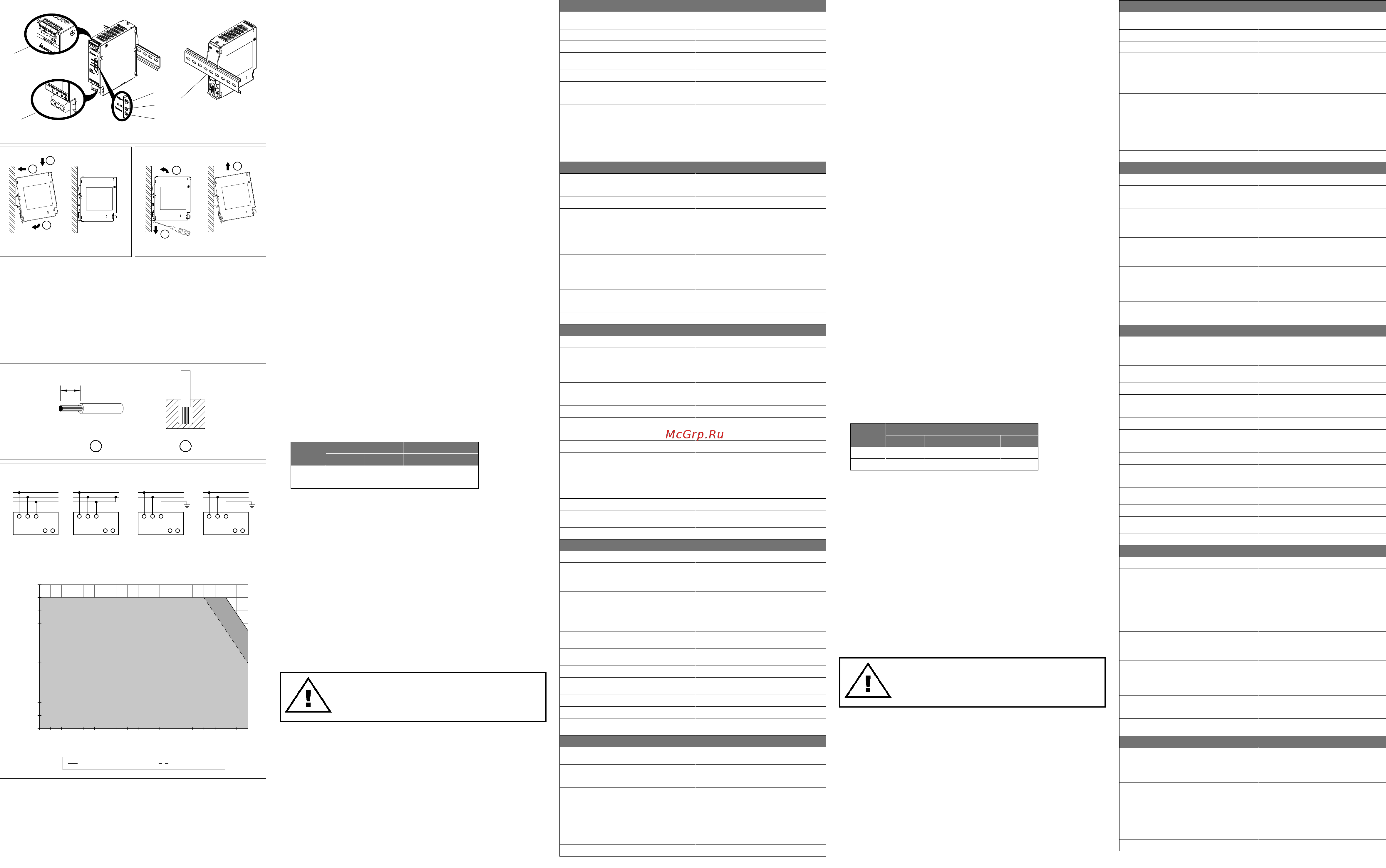
-25 -20 -15 -10 -5 0 5 10 15 20 25 30 35 40 45 50 55 60 65 70
Percentage of Max Load (%)
Surrounding Air Temperature (
o
C)
Vertical Mounting Horizontal Mounting
DEUTSCH
Einbauanleitung
4.2. Anschluss der Ausgangsklemmen (Abb. 1 (2))
Verwenden Sie die Schraubklemmen „+“ und „-“, um den 24Vdc-Anschluss herzustellen. Am
Ausgang stehen 24Vdc zur Verfügung. Die Ausgangsspannung kann am Potentiometer zwischen
24 und 28Vdc eingestellt werden. Die grüne LED “DC OK” zeigt die korrekte Funktion des Ausgangs
an (Abb. 1 (4)). Das Gerät verfügt über einen Kurzschluss-, Überlast- und Überspannungsschutz,
der auf 35Vdc begrenzt ist.
4.3. Ausgangskennlinie
Das Gerät funktioniert normal unter den Betriebsbedingungen für Leitung und Last. Bei Überlast
(I
ü
> 150%) fällt die Ausgangsspannung ab und bewirkt ein Prellen (Bouncing), bis die Überlast
behoben wird. Bei einem Kurzschluss fällt die Sekundärspannung ab und baut sich wieder auf,
nachdem der Kurzschluss behoben wurde.
4.4 Anzeigen und Relaiskontakte (Abb. 4)
4.5 Temperaturverhalten (Abb. 7)
Beträgt die Umgebungstemperatur über +60°C (Vertikal) oder +50°C (Horizontal), muss die
Ausgangsleistung entsprechend dem Temperaturanstieg um 2,5% pro Celsius reduziert werden.
Wird die Ausgangsleistung bei einer Umgebungstemperatur von > 60°C (Vertikal) oder > 50°C
(Horizontal) nicht herabgesetzt, löst der thermische Überlastschutz aus und schaltet das Gerät ab.
Das Gerät bleibt dann so lange in diesem Zustand bis die Umgebungstemperatur oder die Last
soweit abgesenkt wurde, dass das Gerät wieder im Normalbetrieb arbeiten kann.
Die interne Sicherung darf nicht vom Anwender ausge-
tauscht werden. Schicken Sie das Gerät im Fall eines
Defekts zur Reparatur zum Hersteller zurück.
ENGLISH
Installation notes
4.2. Output connection (Fig. 1 (2))
Use the “+” and “-” screw connections to establish the 24Vdc connection. The output provides
24Vdc. The output voltage can be adjusted from 24 to 28Vdc on the potentiometer. The green
LED DC OK displays correct function of the output (Fig. 1 (4)). The device has a short circuit and
overload protection and an over voltage protection limited to 35Vdc.
4.3. Output characteristic curve
The device functions normal under operating line and load conditions. In the event of an over
load (I
O
> 150%) the output voltage will start to droop and bounce until over load has been
removed. If the loads are in short circuit, the secondary voltage will bounce and recover once
the short circuit has been removed.
4.4 Indicators and relay contacts (Fig. 4)
4.5. Thermal behavior (Fig. 7)
In the case of ambient temperatures above +60°C (Vertical) or +50°C (Horizontal), the output
capacity has to be reduced by 2.5% per Celsius increase in temperature. If the output capacity
is not reduced when T
Amb
> 60°C (Vertical) or > 50°C (Horizontal), the device will run into thermal
protection by switching off i.e. device will go in bouncing mode and will recover when ambient
temperature is lowered or load is reduced as far as necessary to keep device in working
condition.
The internal fuse must not be replaced by the user.
In case of internal defect, return the unit for inspection to
the manufacturer.
ENGLISH
Technical data
Input (AC)
Nominal input voltage and frequency 100-240Vac / 50-60Hz; or
110-300Vdc (for ITE only)
Voltage range 85-276Vac (DC input range 88-375Vdc)
Frequency 47-63Hz
Nominal current < 1.00A @ 100Vac, < 0.60A @ 230Vac
< 0.80A @ 110Vdc, < 0.29A @ 300Vdc
Inrush current limitation (+25°C, cold start) 5A typ. @ 120Vac, 10A typ. @ 230Vac
Mains buffering at nominal load 41ms typ. @ 120Vac, 70ms typ. @ 230Vac
Turn-on time < 370ms @ 120Vac, < 330ms @ 230Vac
Internal fuse T 3.15A
- LITTELFUSE (Type 477)
UL E10480: Rated 600Vac & 400Vdc
Europe: Rated 500Vac & 400Vdc
- CONQUER (Type UDE/UDE-A)
UL E82636: Rated 500Vac & 500Vdc
Europe: Rated 500Vac & 500Vdc
Leakage current 0.29mA typ. @ 230Vac
Output (DC)
Nominal output voltage U
N
24Vdc
Factory setting 24.05-24.15Vdc
Adjustment range of the voltage 24-28Vdc
Output current 3.4A (V
out
= 24Vdc)
3A (V
out
= 28Vdc)
5A (for 5s, V
out
= 24Vdc)
4.5A (for 5s, V
out
= 28Vdc)
Derating > 60°C (2.5% / °C) in Vertical
> 50°C (2.5% / °C) in Horizontal
Startup with capacitive loads 8,000µF typ.
Max. power dissipation idling / nominal load approx. 1.5W / 9.1W
Efciency at 100% load 90.1% typ. @ 120Vac, 90.0% typ. @ 230Vac
PARD (20MHz) at 100% load < 50mVpp
Max. relay contact rating 30V (SELV) / 1A resistive load
Parallel operation DRR-20A / DRR-40A
General Data
Type of housing Aluminium
LED signals Green LED DC OK
Red LED Overload
MTBF > 2,000,000 hrs. as per Telcordia SR-332
(I/P: 100Vac; O/P: 24V, 3.4A; Ta: 25°C)
Dimensions (L x W x H) 124mm x 32mm x 102mm
Weight 0.49kg
Connection method Screw connection
Wire stripping length 5mm
Operating temperature (Surrounding air temperature) -25°C to +70°C (Refer to Fig. 7)
Storage temperature -40°C to +85°C
Humidity at +25°C, no condensation 5 to 95% RH
Vibration (non-operating) 10 to 500Hz @ 30m/S² (3G peak); displacement of
0.35mm; 60 min. per axis for all X, Y, Z directions in acc.
with IEC60068-2-6
Shock (in all directions) 30G (300m/S²) in all directions according to
IEC60068-2-27
Pollution degree 2
Altitude (operating) 2500 Meters for industrial application
5000 Meters for ITE application
Climatic class 3K3 according to EN60721
Certication and Standards
Electrical equipments of machines IEC60204-1 (over voltage category III)
Electronic equipment for use in electrical power installations EN50178 / IEC62103
Safety entry low voltage PELV (EN60204), SELV (EN60950)
Electrical safety SIQ to EN60950-1, EN61558-1, EN61558-2-16,
EN61010-1, EN61010-2-201, IEC62103
UL/C-UL recognized to UL60950-1 and CSA C22.2
No. 60950-1
CB scheme to IEC60950-1, IEC61558-1, IEC61558-2-16,
IEC61010-1, IEC61010-2-201
Industrial control equipment UL/C-UL listed to UL508 and CSA C22.2 No. 107.1-01,
CSA to CSA C22.2 No.107.1-01 (File No.181564)
Protection against electric shock DIN57100-410
Maritime DNV GL, Environmental category: C, EMC2
ABS (American Bureau for Shipping) PDA
CE In conformance with EMC directive and low voltage
directive
Component Power Supply for general use EN61204-3
Immunity EN55024, EN61000-6-2, EN61131-2, EN61326-1
Emission EN55011, EN55022, EN61000-3-2, EN61000-3-3,
EN61000-6-4
Safety and Protection
Transient surge voltage protection VARISTOR
Current limitation at short-circuits approx. I
surge
= 150% of Po
max
typically (hiccup mode)
Surge voltage protection against internal surge voltages Yes
Isolation voltage:
Input / Output
Input / PE
Input / DC OK*
Output / PE
Output / DC OK
DC OK / PE
4.58KVac
2.50KVac
4.54KVac
1.50KVac
0.50KVac
1.50KVac
Protection degree IP20
Safety class Class I with PE connection
*Recommend connecting DC OK pins to output pins.
DEUTSCH
Technische Daten
1. Sicherheitsvorschriften
• Es muss eine leicht zugängliche Trennvorrichtung bereitgestellt werden, mit deren Hilfe sich das
Gerät zu Wartungszwecken von der Stromversorgung trennen lässt.
• Schalten Sie die Netzspannung ab, bevor Sie das Gerät an das Netz anschließen oder es vom
Netz trennen. Explosionsgefahr!
• Wird das Gerät anders verwendet als vom Hersteller vorgesehen, werden unter Umständen die
Schutzvorrichtungen des Geräts funktionsunfähig.
• Es muss für eine ausreichende Konvektionskühlung gesorgt werden. Befolgen Sie dazu
bitte nachstehende Anweisungen, damit ein ausreichender Abstand des Geräts zur
Umgebung sichergestellt ist.
Vertikaler Einbau: Oberhalb des Geräts müssen 40 mm und unterhalb 20 mm frei bleiben. Der
seitliche Abstand zu anderen Geräten muss mindestens 5 mm betragen. Handelt es sich bei
dem angrenzenden Gerät um eine Wärmequelle, ist ein Mindestabstand von 15 mm erforderlich.
Horizontaler Einbau: Ober- und unterhalb des Geräts müssen 40 mm frei bleiben. Der
seitliche Abstand zu anderen Geräten muss mindestens 20 mm betragen.
• Das äußere Gehäuse, in das das Gerät verbaut wird, muss den Anforderungen für Mechanik-,
Elektrik- und Brandschutzgehäuse genügen.
• Beachten Sie, dass das Gehäuse des Gerätes sehr heiß werden kann, abhängig von der
Umgebungstemperatur und der Last an der Spannungsversorgung. Verbrennungsgefahr!
• Verbinden und trennen Sie die Anschlüsse nur, wenn die Spannung abgeschaltet ist!
• Führen Sie keine Objekte in das Gerät ein!
• Nachdem das Gerät von allen Spannungsquellen getrennt wurde liegt über einen Zeitraum von
mindestens 5 Minuten noch gefährliche Spannung an dem Gerät an.
• Die Netzgeräte sind eingebaute Geräte und müssen in einem Schrank oder Raum (Innenraum
ohne Kondensation) installiert werden, der relativ frei von leitenden Schmutzstof fen ist.
• VORSICHT:
„Zum Einsatz nur im Innenbereich“.
2. Gerätebeschreibung (Abb. 1)
(1) Eingangsklemmen
(2) Ausgangsklemmen
(3) Potentiometer zur Einstellung der DC-Ausgangsspannung
(4) LED „DC OK“ (grün)
(5) LED „Overload“ (rot)
(6) Universelles Montageschienensystem
3. Montage und demontage (Abb. 2, Abb. 3)
Das Netzteil kann auf 35mm DIN-Schienen gemäß EN60715 montiert werden. Bei vertikalem
Einbau sollte das Gerät so eingebaut werden, dass der Klemmenleistenblock unten ist. Beim
horizontalen Einbau sollte das Gerät so eingebaut werden, dass der Klemmenleistenblock auf der
linken Seite ist.
Jedes Gerät wird installationsfertig geliefert.
1. Kippen Sie das Gerät leicht nach oben und setzen Sie es auf die DIN-Schiene auf.
Einrasten des Geräts in DIN-Schiene, wie in Abb. 2 dargestellt.
2. Kippen Sie das Gerät jetzt wieder nach unten bis zum Anschlag am unteren Teil der Schiene.
3. Drücken Sie nun den unteren Teil des Gerätes so fest gegen die Schiene bis das
Gerät auf der Schiene einrastet.
4. Rütteln Sie leicht am Gerät, um zu überprüfen, ob es korrekt eingerastet ist.
5. Ziehen Sie zur Demontage den Einrasthebel mit einem Schraubendreher nach unten, wie
in Abb. 3 dargestellt. Kippen Sie das Netzteil in die entgegengesetzte Richtung nach oben,
klinken Sie den Einrasthebel aus und nehmen Sie das Netzteil nach oben von der
DIN-Schiene ab.
4. Anschluss
Die Anschlussklemmen erlauben eine schnelle und einfache Verdrahtung des Geräts. Sie können
exible (feindrähtige Leitung) oder feste Kabel mit folgenden Querschnitt verwenden:
Tabelle 1
Um sichere und stoßfeste Anschlüsse gewährleisten zu können, sollte die Abisolierlänge
7mm betragen (siehe Abb. 5 (1)). Bitte sorgen Sie dafür, dass die Kabel vollständig in die
Anschlussklemmen eingeführt werden, siehe Abb. 5 (2). Die Schraubklemmen müssen sicher
befestigt und alle Drahtlitzen in die Klemmen eingeführt sein, um einen sicheren und maximalen
Kontakt sicherzustellen.
Gemäß EN60950 / UL60950 sind für exible Kabel Aderendhülsen erforderlich.
Verwenden Sie geeignete Kupferkabel, die für folgende Betriebstemperaturen ausgelegt sind:
1. 60 °C, 60 °C / 75 °C für USA
2. Mindestens 90 °C für Kanada und IEC/EN61010-1, IEC/EN61010-2-201.
4.1. Anschluss der Eingangsklemmen (Abb. 1, Abb. 6)
Bei Wechselstromeingangsverbindungen müssen die L, N und PE-Anschlüsse am
Eingangsklemmverbinder (siehe Abb. 1(1)) zum Herstellen der Verbindung für 100-240Vac
verwendet werden. Abb. 6 zeigt den Anschluss an die unterschiedlichen Netztypen.
Bei Gleichstromeingangsverbindungen kann folgendermaßen vorgegangen werden:
a) L mit +V
e
und N mit -V
e
verbinden oder
b) L mit -V
e
und N mit +V
e
verbinden.
Das Gerät verfügt über eine interne, nicht austauschbare Sicherung am L-Pin. Es wurde getestet
und zugelassen mit handels üblichen Sicherungen von 20 A (UL) und 16 A (IEC) ohne weitere
Schutzeinrichtungen. Ein externer Schutz ist nur dann notwendig, wenn der Nennstrom größer als
20 A ist. Falls ein externer Schutz zur Anwendung kommt, sollte mindestens eine Sicherung des
Typs 6 A -B oder 6 A -C verwendet werden.
Eingangskennwerte (AC)
Nennspannung en frequentie 100-240Vac / 50-60Hz; oder
110-300Vdc (nur für ITE)
Spannungsbereich 85-276Vac (DC-Eingangsspannungsbereich 88-375Vdc)
Frequenzbereich 47-63Hz
Nennstrom < 1,00A bei 100Vac, < 0,60A bei 230Vac
< 0,80A bei 110Vdc, < 0,29A bei 300Vdc
Einschaltstrombegrenzung (+25°C, Kaltstart) 5A typ. bei 120Vac, 10A typ. bei 230Vac
Netzausfallüberbrückung bei Nennlast 41ms typ. bei 120Vac, 70ms typ. bei 230Vac
Einschaltzeit < 370ms bei 120Vac, < 330ms bei 230Vac
Interne Sicherung T 3,15A
- LITTELFUSE (Type 477)
UL E10480: Rated 600Vac und 400Vdc
Europe: Rated 500Vac und 400Vdc
- CONQUER (Type UDE/UDE-A)
UL E82636: Rated 500Vac und 500Vdc
Europe: Rated 500Vac und 500Vdc
Ableitstrom 0,29mA typ. bei 230Vac
Ausgangskennwerte (DC)
Nennausgangsspannung U
N
24Vdc
Werkseinstellung 24,05-24,15Vdc
Einstellbereich der Ausgangsspannung 24-28Vdc
Ausgangsstrom 3,4A (V
out
= 24Vdc)
3A (V
out
= 28Vdc)
5A (für 5s, V
out
= 24Vdc)
4,5A (für 5s, V
out
= 28Vdc)
Derating (Leistungsherabsetzung) > 60°C (2,5% / °C) Vertikal
> 50°C (2,5% / °C) Horizontal
Anlaufen bei Kapazitiven Lasten 8.000µF typ.
Max. Verlustleistung Leerlauf/Nennlast 1,5W / 9,1W
Wirkungsgrad bei 100% Last 90,1% typ. bei 120Vac, 90,0% typ. bei 230Vac
PARD (20 MHz) bei 100% Last < 50mVpp
Max. Relaisschaltleistung 30V (SELV) / 1A Wirklast
Parallelschaltbarkeit DRR-20A / DRR-40A
Allgemeine Kennwerte
Gehäusetyp Aluminium
LED-Signale Grüne LED „DC OK“
Rot LED „Overload“
MTBF (mittlere Betriebszeit zwischen Ausfällen) > 2.000.000 Std., entsprechend Telcordia SR-332
(I/P: 100Vac; O/P: 24V, 3,4A; Ta: 25°C)
Abmessungen (B x H x T) 124mm x 32mm x 102mm
Gewicht 0,49kg
Art der Anschlussklemme Schraubanschluss
Abisolierlänge 5mm
Betriebstemperaturbereich (Umgebungstemperatur) -25°C bis +70°C (Leistungsherabsetzung gemäß Abb. 7)
Lagertemperaturbereich -40°C bis +85°C
Luftfeuchte bei +25°C, keine Betauung 5 bis 95% relative Luftfeuchte
Vibration (außer Betrieb) 10 bis 500Hz, Beschl. 30m/S², 0,35mm
Einzelamplitude (3G max.) für 60 min. in X, Y & Z
Richtung, gemäß IEC60068-2-6
Stoßfestigkeit (in alle Richtungen) 30G (300m/S²) in alle Richtungen gemäß IEC60068-2-27
Verschmutzungsgrad 2
Höhe (Betrieb) 2500 Meter für die industrielle Anwendung
5000 Meter für ITE-Anwendung
Klimaklasse 3K3 gemäß EN60721
Zertizierung und Normen
Elektrische Ausrüstung von Maschinen IEC60204-1 (Überspannungskategorie III)
Ausrüstung von Starkstromanlagen mit elektronischen
Betriebsmitteln
EN50178 / IEC62103
Schutzkleinspannung PELV (EN60204), SELV (EN60950)
Elektrische Sicherheit SIQ nach EN60950-1, EN61558-1, EN61558-2-16,
EN61010-1, EN61010-2-201, IEC62103
UL/C-UL anerkannt nach UL60950-1 und CSA C22.2
Nr. 60950-1
Prüfprotokoll und -bericht nach IEC60950-1, IEC61558-1,
IEC61558-2-16, IEC61010-1, IEC61010-2-201
Industrielle Regeleinrichtungen UL/C-UL gelistet nach UL508 und CSA C22.2 Nr.107.1-01,
CSA nach CSA C22.2 Nr.107.1-01 (File Nr.181564)
Maritime Anwendungen DNV GL, Umweltkategorie: C, EMC2
ABS (American Bureau for Shipping) PDA
Schutz gegen elektrischen Schlag DIN57100-410
EC In Konformität zur EMV-Richtlinie und
Niederspannungsrichtlinie
Komponenten-Netzteil zur allgemeinen Verwendung EN61204-3
Störfestigkeit
EN55024, EN61000-6-2, EN61131-2, EN61326-1
Emission EN55011, EN55022, EN61000-3-2, EN61000-3-3,
EN61000-6-4
Sicherheit und Schutzeinrichtungen
Überspannungsschutz gegen transiente
Überspannungen
VARISTOR
Strombegrenzung bei Kurzschluss I
Überstrom
= 150% der max. Ausgangsleistung (Hiccup-Modus)
Überspannungsschutz gegen interne Überspannungen Ja
Isolationsspannung
Eingang / Ausgang
Eingang / Schutzleiter
Eingang / DC-OK*
Ausgang / Schutzleiter
Ausgang / DC-OK
DC OK / Schutzleiter
4,58KVac
2,50KVac
4,54KVac
1,50KVac
0,50KVac
1,50KVac
Schutzart IP20
Schutzklasse Klasse I mit Schutzleiteranschluss
*Empfohlene Beschaltung der DC OK und Ausgangs-Pins.
1. Safety instructions
• An easily accessible disconnecting device shall be provided to disconnect the unit from the
mains supply for servicing.
• Switch main power off before connecting or disconnecting the device. Risk of explosion!
• If the unit is used in a manner not specied by the manufacturer, the protection provided by the
equipment may be impaired.
• To guarantee sufcient convection cooling, please refer to the following instructions to ensure
sufcient clearance around the device.
Vertical Mounting: 40mm above and 20mm below the device as well as a lateral
distance of 5mm to other units. In case the adjacent device is a heat source, the lateral
distance will be 15mm.
Horizontal Mounting: 40mm above and below the device as well as a lateral distance of 20mm
to other units.
• The external enclosure where the unit will be installed shall meet the requirements for
mechanical, electrical and re enclosure.
• Note that the enclosure of the device can become very hot depending on the ambient
temperature and load of the power supply. Risk of burns!
• The main power must be turned off before connecting or disconnecting wires to the terminals!
• Do not introduce any objects into the unit!
• Dangerous voltage present for at least 5 minutes after disconnecting all sources of power.
• The power supplies are built in units and must be installed in a cabinet or room
(condensation free environment and indoor location) that is relatively free of conductive
contaminants.
• CAUTION:
“FOR USE IN A CONTROLLED ENVIRONMENT”.
2. Device description (Fig. 1)
(1) Input terminal block connector
(2) Output terminal block connector
(3) DC voltage adjustment potentiometer
(4) DC OK LED (green)
(5) Overload LED (red)
(6) Universal mounting rail system
3. Mounting and dismounting (Fig. 2, Fig. 3)
The power supply unit can be mounted on 35mm DIN rails in accordance with EN60715. For
Vertical Mounting, the device should be installed with input terminal block on the bottom. For
Horizontal Mounting, the device should be installed with input terminal block on the left side.
Each device is delivered ready to install.
1. Tilt the unit slightly upwards and put it onto the DIN rail. Snap on the DIN rail as shown in
Fig. 2.
2. Push downwards until stopped.
3. Press against the bottom front side for locking.
4. Shake the unit slightly to ensure that it is secured.
5. To uninstall, pull or slide down the latch as shown in Fig. 3. Then, slide the PSU in the
opposite direction, release the latch and pull out the PSU from the rail.
4. Connection
The terminal block connectors allow easy and fast wiring.
You can use exible (stranded wire) or solid cables with the following cross sections:
Table 1
To secure reliable and shock proof connections, the stripping length should be 7mm (see Fig. 5
(1)). Please ensure that the wires are fully inserted into the connecting terminals as shown in Fig.
5 (2). All wire strands must be fully inserted into the terminals with the screws securely fastened
in order to ensure safety and maximum contact.
In accordance to EN60950 / UL60950, exible cables require ferrules.
Use appropriate copper cables that are designed to sustain operating temperature of:
1. 60°C, 60°C / 75°C for USA
2. At least 90°C for Canada and IEC/EN61010-1, IEC/EN61010-2-201.
4.1. Input connection (Fig. 1, Fig. 6)
For AC input connections, use L, N and PE connections on the input terminal connector (see
Fig. 1 (1)) to establish the 100-240Vac connection. Fig. 6 shows the connection to the various
network types.
For DC input connections, the following can be done.
a) L connects to +V
e
and N connects to -V
e
or
b) L connects to -V
e
and N connects to +V
e
The unit is protected with internal fuse (not replaceable) at L pin and it has been tested and
approved on 20A (UL) and 16A (IEC) branch circuits without additional protection device. An
external protection device is only required if the supplying branch has an ampacity greater than
above. Thus, if an external protective device is necessary, or, utilized, a minimum value of 6A B-
or 6A C- characteristic breaker should be used.
Figure 1
Figure 4
Figure 6
Figure 5
Refer to
Fig. 1:
Stranded / Solid Torque
(mm²) (AWG) (Kgf-cm) (lb in)
(1) 0.52-8.4 20-8 9.3 8.1
(2) 0.32-1.3 22-16 3.1 2.7
Siehe
Abb. 1:
Flexibel / Starr Anzugsmoment
(mm²) (AWG) (Kgf-cm) (lb in)
(1) 0,52-8,4 20-8 9,3 8,1
(2) 0,32-1,3 22-16 3,1 2,7
Figure 7
Power Derating Curve for PSU
L
N
PE
L N PE
TN-S
L
PEN
L N PE
TN-C
++
L
N
L N PE
TT
+
L
N
L N PE
iT
+
Figure 2 Figure 3
Overload LED DC OK LED DC OK Contact
Normal mode OFF ON Closed
During Power Boost OFF ON Closed
Overload (V
out
< 90%) Flashing OFF Open
Output short circuit Flashing OFF Open
Temperature shut down Flashing OFF Open
No input power OFF OFF Open
1 2
5 mm
(1)
(2)
(3)
(4)
(6)
(5)
1
2
3
1
2
3
1 2
5 mm
(1)
(2)
(3)
(4)
(6)
(5)
1
2
3
1
2
3
1 2
5 mm
(1)
(2)
(3)
(4)
(6)
(5)
1
2
3
1
2
3
1 2
5 mm
(1)
(2)
(3)
(4)
(6)
(5)
1
2
3
1
2
3
Manual_CliQM_80W1P_DRM-24V80W1PN_DECA_rev.01_211016.indd 1 10/21/2016 12:10:05 PM
Содержание
- 1 0 2 8 20 8 9 8 1
- 1 0 52 8 4 20 8 9 3 8 1 1
- 2 0 2 1 22 16 3 2 1
- 2 0 32 1 3 22 16 3 1 2 7 1
- 25 20 15 10 5 0 5 10 15 20 25 30 35 40 45 50 55 60 65 70 1
- 90 flashing off open 1
- And n connects to 1
- Anschluss der ausgangsklemmen abb 1 2 verwenden sie die schraubklemmen und um den 24vdc anschluss herzustellen am ausgang stehen 24vdc zur verfügung die ausgangsspannung kann am potentiometer zwischen 24 und 28vdc eingestellt werden die grüne led dc ok zeigt die korrekte funktion des ausgangs an abb 1 4 das gerät verfügt über einen kurzschluss überlast und überspannungsschutz der auf 35vdc begrenzt ist 1
- Anschluss der eingangsklemmen abb 1 abb 6 bei wechselstromeingangsverbindungen müssen die l n und pe anschlüsse am eingangsklemmverbinder siehe abb 1 1 zum herstellen der verbindung für 100 240vac verwendet werden abb 6 zeigt den anschluss an die unterschiedlichen netztypen 1
- Anschluss die anschlussklemmen erlauben eine schnelle und einfache verdrahtung des geräts sie können flexible feindrähtige leitung oder feste kabel mit folgenden querschnitt verwenden tabelle 1 1
- Anzeigen und relaiskontakte abb 4 1
- At least 90 c for canada and iec en61010 1 iec en61010 2 201 2 at least 90 c for canada and iec en61010 1 iec en61010 2 201 1
- Ausgangskennlinie das gerät funktioniert normal unter den betriebsbedingungen für leitung und last bei überlast 1
- B l connects to v b l connects to 1
- B l mit v b l mit 1
- Beachten sie dass das gehäuse des gerätes sehr heiß werden kann abhängig von der 1
- Bei gleichstromeingangsverbindungen kann folgendermaßen vorgegangen werden a l mit 1
- Bitte nachstehende anweisungen damit ein ausreichender abstand des geräts zur bitte nachstehende anweisungen damit ein ausreichender abstand des geräts zur 1
- C horizontal nicht herabgesetzt löst der thermische überlastschutz aus und schaltet das gerät ab das gerät bleibt dann so lange in diesem zustand bis die umgebungstemperatur oder die last soweit abgesenkt wurde dass das gerät wieder im normalbetrieb arbeiten kann 1
- C horizontal the device will run into thermal protection by switching off i e device will go in bouncing mode and will recover when ambient temperature is lowered or load is reduced as far as necessary to keep device in working condition 1
- Caution 1
- Condensation free environment and indoor location that is relatively free of conductive condensation free environment and indoor location that is relatively free of conductive 1
- Connection the terminal block connectors allow easy and fast wiring 1
- Contaminants contaminants 1
- Das gerät verfügt über eine interne nicht austauschbare sicherung am l pin es wurde getestet und zugelassen mit handels üblichen sicherungen von 20 a ul und 16 a iec ohne weitere schutzeinrichtungen ein externer schutz ist nur dann notwendig wenn der nennstrom größer als 20 a ist falls ein externer schutz zur anwendung kommt sollte mindestens eine sicherung des typs 6 a b oder 6 a c verwendet werden 1
- Das äußere gehäuse in das das gerät verbaut wird muss den anforderungen für mechanik 1
- Dem angrenzenden gerät um eine wärmequelle ist ein mindestabstand von 15 mm erforderlich dem angrenzenden gerät um eine wärmequelle ist ein mindestabstand von 15 mm erforderlich 1
- Deutsch 1
- Device description fig 1 1 input terminal block connector 2 output terminal block connector 3 dc voltage adjustment potentiometer 4 dc ok led green 5 overload led red 6 universal mounting rail system 1
- Die interne sicherung darf nicht vom anwender ausge tauscht werden schicken sie das gerät im fall eines defekts zur reparatur zum hersteller zurück 1
- Die netzgeräte sind eingebaute geräte und müssen in einem schrank oder raum innenraum 1
- Din schiene ab din schiene ab 1
- Distance of 5mm to other units in case the adjacent device is a heat source the lateral distance of 5mm to other units in case the adjacent device is a heat source the lateral 1
- Distance will be 15mm distance will be 15mm 1
- Drücken sie nun den unteren teil des gerätes so fest gegen die schiene bis das 3 drücken sie nun den unteren teil des gerätes so fest gegen die schiene bis das 1
- During power boost off on closed 1
- Each device is delivered ready to install 1 tilt the unit slightly upwards and put it onto the din rail snap on the din rail as shown in 1
- Einbauanleitung 1
- Einrasten des geräts in din schiene wie in abb 2 dargestellt einrasten des geräts in din schiene wie in abb 2 dargestellt 1
- Elektrik und brandschutzgehäuse genügen elektrik und brandschutzgehäuse genügen 1
- English 1
- Es muss für eine ausreichende konvektionskühlung gesorgt werden befolgen sie dazu 1
- Fig 2 fig 2 1
- Figure 1 1
- Figure 2 figure 3 1
- Figure 4 1
- Figure 5 1
- Figure 6 1
- Figure 7 1
- Flexibel starr anzugsmoment 1
- For dc input connections the following can be done a l connects to 1
- Fällt die ausgangsspannung ab und bewirkt ein prellen bouncing bis die überlast behoben wird bei einem kurzschluss fällt die sekundärspannung ab und baut sich wieder auf nachdem der kurzschluss behoben wurde 1
- Führen sie keine objekte in das gerät ein 1
- Gemäß en60950 ul60950 sind für flexible kabel aderendhülsen erforderlich verwenden sie geeignete kupferkabel die für folgende betriebstemperaturen ausgelegt sind 1 60 c 60 c 75 c für usa 1
- Gerät auf der schiene einrastet gerät auf der schiene einrastet 1
- Gerät zu wartungszwecken von der stromversorgung trennen lässt gerät zu wartungszwecken von der stromversorgung trennen lässt 1
- Gerätebeschreibung abb 1 1 eingangsklemmen 2 ausgangsklemmen 3 potentiometer zur einstellung der dc ausgangsspannung 4 led dc ok grün 5 led overload rot 6 universelles montageschienensystem 1
- Horizontal mounting 40mm above and below the device as well as a lateral distance of 20mm horizontal mounting 40mm above and below the device as well as a lateral distance of 20mm 1
- Horizontaler einbau ober und unterhalb des geräts müssen 40 mm frei bleiben der horizontaler einbau ober und unterhalb des geräts müssen 40 mm frei bleiben der 1
- In abb 3 dargestellt kippen sie das netzteil in die entgegengesetzte richtung nach oben in abb 3 dargestellt kippen sie das netzteil in die entgegengesetzte richtung nach oben 1
- In accordance to en60950 ul60950 flexible cables require ferrules use appropriate copper cables that are designed to sustain operating temperature of 1 60 c 60 c 75 c for usa 1
- Indicators and relay contacts fig 4 1
- Input connection fig 1 fig 6 for ac input connections use l n and pe connections on the input terminal connector see fig 1 1 to establish the 100 240vac connection fig 6 shows the connection to the various network types 1
- Installation notes 1
- Jedes gerät wird installationsfertig geliefert 1 kippen sie das gerät leicht nach oben und setzen sie es auf die din schiene auf 1
- Kippen sie das gerät jetzt wieder nach unten bis zum anschlag am unteren teil der schiene 2 kippen sie das gerät jetzt wieder nach unten bis zum anschlag am unteren teil der schiene 1
- Klinken sie den einrasthebel aus und nehmen sie das netzteil nach oben von der klinken sie den einrasthebel aus und nehmen sie das netzteil nach oben von der 1
- Manual_cliqm_80w1p_drm 24v80w1pn_deca_rev 1_211016 indd 1 10 21 2016 12 10 05 pm 1
- Mindestens 5 minuten noch gefährliche spannung an dem gerät an mindestens 5 minuten noch gefährliche spannung an dem gerät an 1
- Mindestens 90 c für kanada und iec en61010 1 iec en61010 2 201 2 mindestens 90 c für kanada und iec en61010 1 iec en61010 2 201 1
- Mm² awg kgf cm lb in 1
- Montage und demontage abb 2 abb 3 das netzteil kann auf 35mm din schienen gemäß en60715 montiert werden bei vertikalem einbau sollte das gerät so eingebaut werden dass der klemmenleistenblock unten ist beim horizontalen einbau sollte das gerät so eingebaut werden dass der klemmenleistenblock auf der linken seite ist 1
- Mounting and dismounting fig 2 fig 3 the power supply unit can be mounted on 35mm din rails in accordance with en60715 for vertical mounting the device should be installed with input terminal block on the bottom for horizontal mounting the device should be installed with input terminal block on the left side 1
- Nachdem das gerät von allen spannungsquellen getrennt wurde liegt über einen zeitraum von 1
- Netz trennen explosionsgefahr netz trennen explosionsgefahr 1
- No input power off off open 1
- Normal mode off on closed 1
- Note that the enclosure of the device can become very hot depending on the ambient temperature and load of the power supply risk of burns 1
- Ohne kondensation installiert werden der relativ frei von leitenden schmutzstof fen ist ohne kondensation installiert werden der relativ frei von leitenden schmutzstof fen ist 1
- Opposite direction release the latch and pull out the psu from the rail opposite direction release the latch and pull out the psu from the rail 1
- Output characteristic curve the device functions normal under operating line and load conditions in the event of an over load 1
- Output connection fig 1 2 use the and screw connections to establish the 24vdc connection the output provides 24vdc the output voltage can be adjusted from 24 to 28vdc on the potentiometer the green led dc ok displays correct function of the output fig 1 4 the device has a short circuit and overload protection and an over voltage protection limited to 35vdc 1
- Output short circuit flashing off open 1
- Overload 1
- Overload led dc ok led dc ok contact 1
- Percentage of max load 1
- Power derating curve for psu 1
- Press against the bottom front side for locking 3 press against the bottom front side for locking 1
- Push downwards until stopped 2 push downwards until stopped 1
- Refer to fig 1 1
- Rütteln sie leicht am gerät um zu überprüfen ob es korrekt eingerastet ist 4 rütteln sie leicht am gerät um zu überprüfen ob es korrekt eingerastet ist 1
- Safety instructions an easily accessible disconnecting device shall be provided to disconnect the unit from the mains supply for servicing 1
- Schalten sie die netzspannung ab bevor sie das gerät an das netz anschließen oder es vom 1
- Schutzvorrichtungen des geräts funktionsunfähig schutzvorrichtungen des geräts funktionsunfähig 1
- Seitliche abstand zu anderen geräten muss mindestens 20 mm betragen seitliche abstand zu anderen geräten muss mindestens 20 mm betragen 1
- Seitliche abstand zu anderen geräten muss mindestens 5 mm betragen handelt es sich bei seitliche abstand zu anderen geräten muss mindestens 5 mm betragen handelt es sich bei 1
- Shake the unit slightly to ensure that it is secured 4 shake the unit slightly to ensure that it is secured 1
- Sicherheitsvorschriften es muss eine leicht zugängliche trennvorrichtung bereitgestellt werden mit deren hilfe sich das 1
- Siehe abb 1 1
- Stranded solid torque 1
- Surrounding air temperature 1
- Switch main power off before connecting or disconnecting the device risk of explosion if the unit is used in a manner not specified by the manufacturer the protection provided by the equipment may be impaired 1
- Technical data 1
- Technische daten 1
- Temperature shut down flashing off open 1
- The external enclosure where the unit will be installed shall meet the requirements for mechanical electrical and fire enclosure 1
- The internal fuse must not be replaced by the user in case of internal defect return the unit for inspection to the manufacturer 1
- The main power must be turned off before connecting or disconnecting wires to the terminals do not introduce any objects into the unit dangerous voltage present for at least 5 minutes after disconnecting all sources of power the power supplies are built in units and must be installed in a cabinet or room 1
- The output voltage will start to droop and bounce until over load has been removed if the loads are in short circuit the secondary voltage will bounce and recover once the short circuit has been removed 1
- The unit is protected with internal fuse not replaceable at l pin and it has been tested and approved on 20a ul and 16a iec branch circuits without additional protection device an external protection device is only required if the supplying branch has an ampacity greater than above thus if an external protective device is necessary or utilized a minimum value of 6a b or 6a c characteristic breaker should be used 1
- Thermal behavior fig 7 in the case of ambient temperatures above 60 c vertical or 50 c horizontal the output capacity has to be reduced by 2 per celsius increase in temperature if the output capacity is not reduced when 1
- To guarantee sufficient convection cooling please refer to the following instructions to ensure sufficient clearance around the device 1
- To other units to other units 1
- To secure reliable and shock proof connections the stripping length should be 7mm see fig 5 1 please ensure that the wires are fully inserted into the connecting terminals as shown in fig 5 2 all wire strands must be fully inserted into the terminals with the screws securely fastened in order to ensure safety and maximum contact 1
- To uninstall pull or slide down the latch as shown in fig 3 then slide the psu in the 5 to uninstall pull or slide down the latch as shown in fig 3 then slide the psu in the 1
- Um sichere und stoßfeste anschlüsse gewährleisten zu können sollte die abisolierlänge 7mm betragen siehe abb 5 1 bitte sorgen sie dafür dass die kabel vollständig in die anschlussklemmen eingeführt werden siehe abb 5 2 die schraubklemmen müssen sicher befestigt und alle drahtlitzen in die klemmen eingeführt sein um einen sicheren und maximalen kontakt sicherzustellen 1
- Umgebung sichergestellt ist umgebung sichergestellt ist 1
- Umgebungstemperatur und der last an der spannungsversorgung verbrennungsgefahr umgebungstemperatur und der last an der spannungsversorgung verbrennungsgefahr 1
- Und n mit 1
- Verbinden 1
- Verbinden oder 1
- Verbinden und trennen sie die anschlüsse nur wenn die spannung abgeschaltet ist 1
- Vertical mounting 40mm above and 20mm below the device as well as a lateral vertical mounting 40mm above and 20mm below the device as well as a lateral 1
- Vertical mounting horizontal mounting 1
- Vertikaler einbau oberhalb des geräts müssen 40 mm und unterhalb 20 mm frei bleiben der vertikaler einbau oberhalb des geräts müssen 40 mm und unterhalb 20 mm frei bleiben der 1
- Vorsicht 1
- Wird das gerät anders verwendet als vom hersteller vorgesehen werden unter umständen die 1
- You can use flexible stranded wire or solid cables with the following cross sections table 1 1
- Ziehen sie zur demontage den einrasthebel mit einem schraubendreher nach unten wie 5 ziehen sie zur demontage den einrasthebel mit einem schraubendreher nach unten wie 1
- 1 0 2 8 20 8 9 8 2
- 1 0 52 8 4 20 8 9 3 8 1 2
- 2 0 2 1 22 16 3 2 2
- 2 0 32 1 3 22 16 3 1 2 7 2
- 4 dc ok 2
- 5 overloa 2
- Afin de garantir un refroidissement par convection suffisant veuillez vous référer aux instructions 2
- Appuyez sur la face inférieure de l appareil pour le verrouiller en place 3 appuyez sur la face inférieure de l appareil pour le verrouiller en place 2
- Après déconnexion de toutes ses sources d alimentation une tension rémanente dangereuse 2
- Attention 2
- Au moins 90 c pour le canada et iec en61010 1 iec en61010 2 201 2 au moins 90 c pour le canada et iec en61010 1 iec en61010 2 201 2
- B connecter l à v b connecter l à 2
- C 60 c 75 2
- C horizontale l appareil s arrête et passe en mode de protection thermique c est à dire qu il passe en régime de rebondissement et qu il redémarrera lorsque la température ou la charge auront été suffisamment réduites pour rétablir les conditions nominales de fonctionnement 2
- Celsiu 2
- Cn 安装注意事项 2
- Comportement thermique fig 7 si la température ambiante dépasse 60 c verticale ou 50 c horizontale la capacité de sortie doit être réduite de 2 5 par degré celsius d accroissement de la température si la capacité de sortie n est pas réduite lorsque 2
- Consignes de sécurité un dispositif de déconnexion facile d accès doit être fourni pour déconnecter l appareil de 2
- Courbe caractéristique de sortie l appareil fonctionne normalement dans les conditions d exploitation de ligne et de charge en cas de surcharge 2
- Danger d explosion danger d explosion 2
- De contaminants conducteurs de contaminants conducteurs 2
- De einbauanleitung 2
- Delta cliq m power supply system 1ac 24vdc 3 a 2
- Description de l appareil fig 1 1 connecteur bornier d entrée 2 connecteur bornier de sortie 3 potentiomètre de réglage de tension continue cc 4 led cc ok verte 5 led overload rouge 6 rail de montage universel 2
- Données techniques 2
- En installation notes 2
- En60715 2
- En60950 ul6095 2
- Enlevez l appareil du rail enlevez l appareil du rail 2
- Et connecter n à 2
- Fig 1 1 2
- Fig 1 fig 6 2
- Fig 2 fig 3 2
- Fig 5 1 2
- Fig 5 2 2
- Fournie par l équipement peut être affectée fournie par l équipement peut être affectée 2
- Fr instruction d installation 2
- Français 2
- Iec en61010 1 iec en61010 2 20 2
- Indicateurs et contacts relais fig 4 2
- Instruction d installation 2
- L alimentation par le réseau pour la maintenance l alimentation par le réseau pour la maintenance 2
- L appareil est livré prêt à installer 1 inclinez l appareil légèrement vers le haut et placez le sur le rail din encliquetez le sur le 2
- L appareil peut s échauffer considérablement risque de brûlure l appareil peut s échauffer considérablement risque de brûlure 2
- L unité est protégée par un fusible interne non remplaçable sur la pin l et il a été testé et approuvé sur 20 a ul et 16 a iec la connexion avec des équipements externes ne nécessite pas de protection supplémentaire une protection externe est seulement exigé si le courant de charge est supérieur aux caractéristiques d ampacités mentionnés ainsi si un dispositif de protection externe est nécessaire on doit utiliser une fonction disjoncteur d une valeur minimale de 6 a b ou 6 a c 2
- La tension de sortie commence à chuter et rebondir jusqu à élimination de la surcharge si les charges sont court circuitées la tension secondaire chutera et rebondira après élimination du court circuit 2
- Latéral de 20mm avec les autres appareils latéral de 20mm avec les autres appareils 2
- Latéral de 5 mm avec les autres appareils dans le cas où le dispositif adjacent représente une latéral de 5 mm avec les autres appareils dans le cas où le dispositif adjacent représente une 2
- Le boîtier externe dans lequel l appareil sera installé doit être conforme aux exigences en 2
- Le câble doit être dénudé sur 7mm pour assurer une connexion fiable et résistante au choc voir fig 5 1 merci de s assurer que les fils sont entièrement insérés dans le connecteur comme montré en fig 5 2 les bornes à vis doivent être solidement fixées et tous les torons doivent être insérés dans les bornes afin d assurer la sécurité et un contact maximal 2
- Le fusible interne ne doit pas être remplacé par l utilisateur en cas de défaut interne vous devez retour ner l appareil au fabricant pour examen 2
- Les alimentations sont des unités intégrées et doivent être installées dans une armoire 2
- Les normes en60950 ul60950 stipulent d utiliser une bague pour les câbles souples utiliser des câbles en cuivre adaptés conçus pour résister à une température de service de 1 60 c 60 c 75 c pour les usa 2
- Manual_cliqm_80w1p_drm 24v80w1pn_deca_rev 1_211016 indd 2 10 21 2016 12 10 08 pm 2
- Matière de protection mécanique électrique et coupe feu matière de protection mécanique électrique et coupe feu 2
- Mettez l alimentation générale hors tension avant de connecter ou de déconnecter l appareil 2
- Mettez toujours hors tension avant de connecter ou de déconnecter un connecteur 2
- Mm² awg kgf cm lb in 2
- Montage et démontage fig 2 fig 3 le bloc d alimentation peut être monté sur rail din de 35mm selon l en60715 pour le montage vertical le dispositif doit être installé avec le bloc de connections d entrée vers le bas pour le montage horizontal le dispositif doit être installé avec le bloc de connections d entrée du coté gauche 2
- Montage horizontal 40 mm au dessus et 20 mm au dessous du dispositif ainsi qu un écart montage horizontal 40 mm au dessus et 20 mm au dessous du dispositif ainsi qu un écart 2
- Montage vertical 40 mm au dessus et 20 mm au dessous du dispositif ainsi qu un écart montage vertical 40 mm au dessus et 20 mm au dessous du dispositif ainsi qu un écart 2
- N introduisez aucun objet dans l appareil 2
- Ou dans une salle emplacement couvert et sans condensation qui est relativement exempte ou dans une salle emplacement couvert et sans condensation qui est relativement exempte 2
- Pour démonter l appareil tirez ou faites coulisser le loquet vers le bas comme indiqué 5 pour démonter l appareil tirez ou faites coulisser le loquet vers le bas comme indiqué 2
- Pour les connexions d entrée cc vous pouvez procéder de la manière suivante a connecter l à 2
- Poussez le vers le bas jusqu en butée 2 poussez le vers le bas jusqu en butée 2
- Raccordement d entrée fig 1 fig 6 pour les connexions d entrée ca utilisez les raccords l n et pe sur le connecteur de la borne d entrée voir fig 1 1 afin d établir la connexion 100 240 vca le raccordement aux divers types de réseau est représenté à la fig 6 2
- Raccordement de sortie fig 1 2 utilisez les bornes à vis et pour relier au 24vcc la sortie délivre un courant en 24vcc la tension de sortie peut être réglée entre 24 et 28vcc à l aide du potentiomètre le voyant del ok vert indique le bon fonctionnement de la sortie fig 1 4 l appareil est équipé d une protection de court circuit et contre les surcharges ainsi que d une protection contre les surtensions réglée à 35vcc 2
- Raccordements les connecteurs de bornier permettent de raccorder facilement et rapidement 2
- Rail din comme indiqué à la fig 2 rail din comme indiqué à la fig 2 2
- Refer to fig 1 2
- Remarque selon la température ambiante et la charge de l alimentation électrique le boîtier de 2
- Reste appliquée à l appareil pendant au moins 5 minutes reste appliquée à l appareil pendant au moins 5 minutes 2
- Référer à la fig 1 2
- Secouez légèrement l appareil pour vérifier qu il est bien fixé 4 secouez légèrement l appareil pour vérifier qu il est bien fixé 2
- Si l appareil est utilisé de manière non conforme aux spécifications du fabricant la protection 2
- Souple rigide couple de serrage 2
- Source de chaleur la distance latérale est portée à 15 mm source de chaleur la distance latérale est portée à 15 mm 2
- Suivantes pour assurer un espace suffisant autour du dispositif suivantes pour assurer un espace suffisant autour du dispositif 2
- Vous pouvez utiliser du câble souple conducteurs torsadé ou rigide avec les sections suivantes tableau 1 2
- Www deltapsu com 2
- À la fig 3 faites coulisser l appareil dans la direction opposée relâchez le loquet et à la fig 3 faites coulisser l appareil dans la direction opposée relâchez le loquet et 2
- 中文 2
- 可以使用以下多股或实心的电线 table 1 2
- 多股 实心电线 扭矩 2
- 安装注意事项 2
- 技术数据及规格 2
- 注意 2
- 电线规范 awg kgf cm lb in 2
- 载面积 m 2
Похожие устройства
- Delta Electronics DRM-24V480W1PN Чертеж
- Delta Electronics DRM-24V480W1PN Инструкция по эксплуатации(ENG)
- Delta Electronics DRM-24V240W1PN Чертеж
- Delta Electronics DRM-24V240W1PN Инструкция по эксплуатации(ENG)
- Delta Electronics DRM-24V120W1PN Чертеж
- Delta Electronics DRM-24V120W1PN Инструкция по эксплуатации(ENG)
- Delta Electronics DRU-24V40ABN Инструкция по эксплуатации(ENG)
- Delta Electronics DRR-20A Инструкция по эксплуатации(ENG)
- Delta Electronics DRB-24V040ABN Инструкция по эксплуатации(ENG)
- Delta Electronics DRB-24V020ABA Инструкция по эксплуатации(ENG)
- Delta Electronics DRP024V480W3AA Инструкция по эксплуатации(ENG)
- Delta Electronics DRP024V480W1AA Инструкция по эксплуатации(ENG)
- Delta Electronics DRP024V240W3AA Инструкция по эксплуатации(ENG)
- Ecotronic F2-U4 Руководство пользователя
- Ecotronic С21-U4L Руководство пользователя
- Ecotronic H1-U4LE Руководство пользователя
- Ecotronic H1-U4L Руководство пользователя
- Ecotronic M15-U4LKEM Руководство пользователя
- Delta Electronics DRP024V240W1BA Инструкция по эксплуатации(ENG)
- Delta Electronics DRP024V240W1AA Инструкция по эксплуатации(ENG)