
Delta Electronics DRP024V480W3AA Инструкция по эксплуатации(ENG) онлайн
0
10
20
30
40
50
60
70
80
90
100
110
-20 -10 0 10 20 30 40 50 60 70 80
Percentage of Max Load (%)
Surrounding air temperature
(
o
C)
DEUTSCH
Anleitung
5.2. Anschluss der Ausgangsklemmen (Abb. 1 (2))
Verwenden Sie die Schraubklemmen „+“ und „-“, um den 24Vdc-Anschluss herzu-
stellen. Am Ausgang stehen 24Vdc zur Verfügung. Die Ausgangsspannung kann am
Potentiometer zwischen 22 und 28Vdc eingestellt werden. Die grüne LED “DC OK”
zeigt die korrekte Funktion des Ausgangs an (Abb. 1 (4)). Das Gerät verfügt über
einen Kurzschluss-, Überlast- und Überspannungsschutz, der auf 35Vdc begrenzt ist.
5.3. Ausgangskennlinie
Das Gerät funktioniert normal, solange die Netz- und Lastbedingungen im Betriebs-
bereich des Geräts liegen. Im Fall eines Kurzschlusses oder einer Überlast fallen
Ausgangsspannung und –strom ab (bei I
Überlast
bzw. I
Kurzschluss
> I
Überstrom
(150%)). Die Se-
kundärspannung wird dabei so lange abgesenkt, bis der sekundärseitige Kurzschluss
oder die Überlast behoben sind.
5.4. Temperaturverhalten (Abb. 6)
Beträgt die Umgebungstemperatur über +50°C, muss die Ausgangsleistung entspre-
chend dem Temperaturanstieg um 2,5% pro Celsius reduziert werden. Wird die Aus-
gangsleistung bei einer Umgebungstemperatur von > 50°C nicht herabgesetzt, löst
der thermische Überlastschutz aus und schaltet das Gerät ab. Das Gerät bleibt dann
so lange in diesem Zustand bis die Umgebungstemperatur oder die Last soweit abge-
senkt wurde, dass das Gerät wieder im Normalbetrieb arbeiten kann.
Die interne Sicherung darf nicht vom Anwender ausge-
tauscht werden. Schicken Sie das Gerät im Fall eines
Defekts zur Reparatur zum Hersteller zurück.
ENGLISH
Installation notes
5.2. Output connection (Fig. 1 (2))
Use the “+” and “-“ screw connections to establish the 24Vdc connection. The output
provides 24Vdc. The output voltage can be adjusted from 22 to 28Vdc on the poten-
tiometer. The green LED DC OK displays correct function of the output (Fig. 1 (4)).
The device has a short circuit and overload protection and an over voltage protection
limited to 35Vdc.
5.3. Output characteristic curve
The device functions normal under operating line and load conditions. In the event of
a short circuit or over load the output voltage and current collapses (I
O/L
or I
S/C
is > I
surge
(150%)). The secondary voltage is reduced and bounces until short circuit or over load
on the secondary side has been removed.
5.4. Thermal behavior (Fig. 6)
In the case of ambient temperatures above +50°C, the output capacity has to be re-
duced by 2.5% per degree Celsius increase in temperature. If the output capacity is not
reduced when T
Amb
> 50°C device will run into thermal protection by switching off i.e.
device will go in bouncing mode and will recover when ambient temperature is lowered
or load is reduced as far as necessary to keep device in working condition.
The internal fuse must not be replaced by the user.
In case of internal defect, return the unit for inspection to
the manufacturer.
ENGLISH
Technical data
Input (AC)
Nominal input voltage 3 x 400-500Vac
Voltage range 320-575Vac (DC input range 450-800Vdc)
Frequency 47-63Hz (0Hz @ DC input)
Nominal current < 1.60A @ 400Vac, < 1.10A @ 500Vac
Inrush current limitation. I
2
t (+25°C) typ. < 50A @ 3 x 400Vac & 3 x 500Vac
Mains buffering at nominal load (typ.) > 25ms @ 3 x 400Vac, > 50ms @ 3 x 500Vac
Turn-on time < 1 sec.
Internal fuse 3.15 AH / 500V
Recommended backup fuse:
Power circuit-breaker characteristic
3 x circuit breakers 6A, 10A or 16A
B
Leakage current < 3.5mA @ 500Vac
Output (DC)
Nominal output voltage U
N
/ tolerance 24Vdc ± 2%
Adjustment range of the voltage 22-28Vdc
Nominal current 20A
Derating above +50°C 2.5% / °C
Startup with capacitive loads Max. 10,000µF
Max. power dissipation idling / nominal load approx. 72W
Efciency (at 400Vac & 500Vac and nominal values) > 87% @ 3 x 400Vac & 3 x 500Vac
Residual ripple/ peak switching (20MHz) (at nominal values) < 50mVpp / < 240mVpp
Parallel operation DRR-40A / With ORing Diode
General Data
Type of housing Aluminium (Al5052)
Signals Green LED DC OK
MTBF > 300,000 hrs.
Dimensions (L x W x H) 121mm x 160mm x 119mm
Weight 1.71kg
Connection method Screw connection
Stripping length 7mm or use suitable lug to crimp
Operating temperature (surrounding air temperature) -20°C to +75°C (> 50°C derating)
Storage temperature -25°C to +85°C
Humidity at +25°C, no condensation < 95% RH
Vibration (non-operating) 10 to 150Hz, 0.35mm acc. 50m / s², single amplitude
(3G max.) for 90 min. in each X, Y & Z directions, in acc.
with IEC60068-2-6
Shock (in all directions) 30G (300m/s²) in all directions according to
IEC60068-2-27
Pollution degree 2
Climatic class 3K3 according to EN60721
Certication and Standards
Electrical equipments of machines IEC60204-1 (over voltage category III)
Electronic equipment for use in electrical power installations EN50178 / IEC62103
Safety entry low voltage PELV (EN60204), SELV (EN60950)
Electrical safety (of information technology equipment) EN60950-1 (GS-mark), UL/C-UL recognized to
UL60950-1, CSA C22.2 No. 60950-1, CB scheme to
IEC60950-1, cCSAus to UL60950-1 and CSA C22.2 No.
60950-1 (File no.181564)
Industrial control equipment UL listed to UL508 and CSA to CSA C22.2 No. 107.1-01
(File no.181564)
Hazardous location / ATEX cCSAus to CSA C22.2 No.213-M1987, ANSI / ISA
12.12.01:2007
Class I, Division 2, Group A,B,C,D T4, Ta = -20°C
to +80°C (> +50°C derating); IEC/EN60079-0, IEC/
EN60079-15 (
ATE X II3G
IE CE X
II3 G EX nA IIC T4,Ta = -20°C to
+80°C (> +50°C derating))
II3G ATEX 94/9/EC
IECEx test report
Certicate no. ESP 09 ATEX 1 215 X;
For IEC60079-0, IEC60079-15
Protection against electric shock DIN57100-410
CE In conformance with EMC directive 2004/108/EC and
low voltage directive 2006/95/EC
ITE EN55022, EN61000-3-2, EN61000-3-3, EN55024
Industrial EN55011
Limitation of mains harmonic currents EN61000-3-2
Voltage Sag Immunity SEMI F47 - 0706
Safety and Protection
Transient surge voltage protection VARISTOR
Current limitation at short-circuits approx. I
surge
= 150% of Po
max
typically
Surge voltage protection against internal surge voltages Yes
Isolation voltage:
Input / output (type test/routine test)
Input / PE (type test/routine test)
Output / PE (type test/routine test)
4.0KVac / 3.0KVac
1.5KVac / 1.5KVac
1.5KVac / 0.5KVac
Protection degree IPX0
Safety class Class I with PE connection
DEUTSCH
Technische Daten
Eingangskennwerte (AC)
Nennspannung 3 x 400-500Vac
Spannungsbereich (autom. Auswahl) 320-575Vac (DC-Eingangsspannungsbereich 450-
800Vdc)
Frequenzbereich 47-63Hz (0Hz bei DC Eingangsspannung)
Nennstrom < 1,60A bei 400Vac, < 1,10A bei 500Vac
Einschaltstrombegrenzung I²t (+25°C) typ. < 50A bei 3 x 400Vac & 3 x 500Vac
Netzausfallüberbrückung bei Nennlast (typ.) > 25ms bei 3 x 400Vac, > 50ms bei 3 x 500Vac
Einschaltzeit < 1 sec.
Interne Sicherung 3,15 AH / 500V
Empfohlene Vorsicherung:
Auslösecharakteristik Leistungsschalter
6A, 10A oder 16A
B
Ableitstrom < 3,5mA bei 500Vac
Ausgangskennwerte (DC)
Nennausgangsspannung UN / Toleranz 24Vdc ± 2%
Einstellbereich der Ausgangsspannung 22-28Vdc
Nennstrom 20A
Derating (Leistungsherabsetzung) ab T
amb
> +50°C 2,5% / °C Temperaturerhöhung
Anlaufen bei Kapazitiven Lasten Max. 10.000µF
Max. Verlustleistung Leerlauf/Nennlast 72W
Wirkungsgrad (bei 400Vac & 500Vac und Nennwerten) > 87.0% bei 3 x 400Vac & 3 x 500Vac
Restwelligkeit / Schaltspitzen (20MHz) (bei Nennwerten) < 50mVpp / < 240mVpp
Parallelschaltbarkeit DRR-40A / mit ORing Diode
Allgemeine Kennwerte
Gehäusetyp Aluminium (Al5052)
Statusanzeige Grüne LED „DC OK“
MTBF (mittlere Betriebszeit zwischen Ausfällen) > 300.000 Std.
Abmessungen (B x H x T) 121mm x 160mm x 119mm
Gewicht 1,71kg
Art der Anschlussklemme Schraubanschluss
Abisolierlänge 7mm oder geeigneter Kabelschuh zum Quetschen
Betriebstemperaturbereich (Umgebungstemperatur) -20°C bis +75°C (> 50°C derating)
Lagertemperaturbereich -25°C bis +85°C
Luftfeuchte bei +25°C, keine Betauung < 95 relative Luftfeuchte
Vibration (außer Betrieb) 10 bis 150Hz, Beschl. 50m / s², 0,35mm
Einzelamplitude (3G max.) für 90 min. in X, Y & Z
Richtung, gemäß IEC60068-2-6
Stoßfestigkeit (in alle Richtungen) 30g (300m/s²) in alle Richtungen gemäß
IEC60068-2-27
Verschmutzungsgrad 2
Klimaklasse 3K3 gemäß EN60721
Zertizierung und Normen
Elektrische Ausrüstung von Maschinen IEC60204-1 (Überspannungskategorie III)
Ausrüstung von Starkstromanlagen mit elektronischen
Betriebsmitteln
EN50178 / IEC62103
Schutzkleinspannung PELV (EN60204), SELV (EN60950)
Elektrische Sicherheit (von Einrichtungen der Informati-
onstechnik)
EN60950-1 (GS-Zeichen), UL/C-UL recognized to
UL60950-1, CSA C22.2 No. 60950-1, CB scheme to
IEC60950-1, cCSAus to UL60950-1 and CSA C22.2 No.
60950-1 (File no.181564)
Industrielle Regeleinrichtungen UL gelistet UL508 und CSA to CSA C22.2 No. 107.1-01
(File no.181564)
Gefährlicher Bereich / ATEX cCSAus bis CSA C22.2 No.213-M1987, ANSI / ISA
12.12.01:2007
Klasse I, Division 2, Gruppe A,B,C,D T4, Ta = -20°C
bis +80°C (> +50°C derating); IEC/EN60079-0, IEC/
EN60079-15 ( II3 G EX nA IIC T4,Ta = -20°C bis
+80°C (> +50°C derating))
II3G ATEX 94/9/EC
IECEx Testbericht
Zertikat Nr. ESP 09 ATEX 1 215 X;
Für IEC60079-0, IEC60079-15
Schutz gegen elektrischen Schlag DIN57100-410
EC In Konformität zur EMV-Richtlinie 2004/108/EC und
Niederspannungsrichtlinie 2006/95/EC
ITE EN55022, EN61000-3-2, EN61000-3-3, EN55024
Industrial EN55011
Begrenzung der Netzoberschwingungen EN61000-3-2
Voltage Sag Immunity SEMI F47 - 0706
Sicherheit und Schutzeinrichtungen
Überspannungsschutz gegen transiente
Überspannungen
VARISTOR
Strombegrenzung bei Kurzschluss I
Überstrom
= 150% der max. Ausgangsleistung
Überspannungsschutz gegen interne Überspannungen Ja
Isolationsspannung
Eingang / Ausgang (Typprüfung/Stückprüfung)
Eingang / Schutzleiter (Typprüfung/Stückprüfung)
Ausgang / Schutzleiter (Typprüfung/Stückprüfung)
4,0KVac / 3,0KVac
1,5KVac / 1,5KVac
1,5KVac / 0,5KVac
Schutzart IPX0
Schutzklasse Klasse I mit Schutzleiteranschluss
1. Sicherheitsvorschriften
• Schalten Sie die Netzspannung ab, bevor Sie das Gerät an das Netz anschließen
oder es vom Netz trennen. Explosionsgefahr!
• Um eine ausreichende Konvektionskühlung zu gewährleisten, halten Sie ober-
und unterhalb des Gerätes einen Abstand von 50mm ein sowie einen seitlichen
Abstand von 20mm zu anderen Geräten.
• Beachten Sie, dass das Gehäuse des Gerätes sehr heiß werden kann, abhängig
von der Umgebungstemperatur und der Last an der Spannungsversorgung.
Verbrennungsgefahr!
• Verbinden und trennen Sie die Anschlüsse nur, wenn die Spannung abgeschaltet
ist!
• Führen Sie keine Objekte in das Gerät ein!
• Nachdem das Gerät von allen Spannungsquellen getrennt wurde liegt über einen
Zeitraum von mindestens 5 Minuten noch gefährliche Spannung an dem Gerät an.
• Das Netzgerät muss in einem Gehäuse installiert sein, das mindestens der
Schutzklasse IP54 entspricht.
• Vorsicht: „Zum Einsatz nur im Innenbereich“.
• Warnung: Explosionsgefahr – Das Austauschen von Komponenten kann die
Eignung für Klasse 1, Abteilung 2 beeinträchtigen.
• Warnung: Explosionsgefahr – Anlage nur dann abtrennen, wenn die Stromversor
gung unterbrochen oder die Umgebung als nicht gefährlich eingestuft wurde.
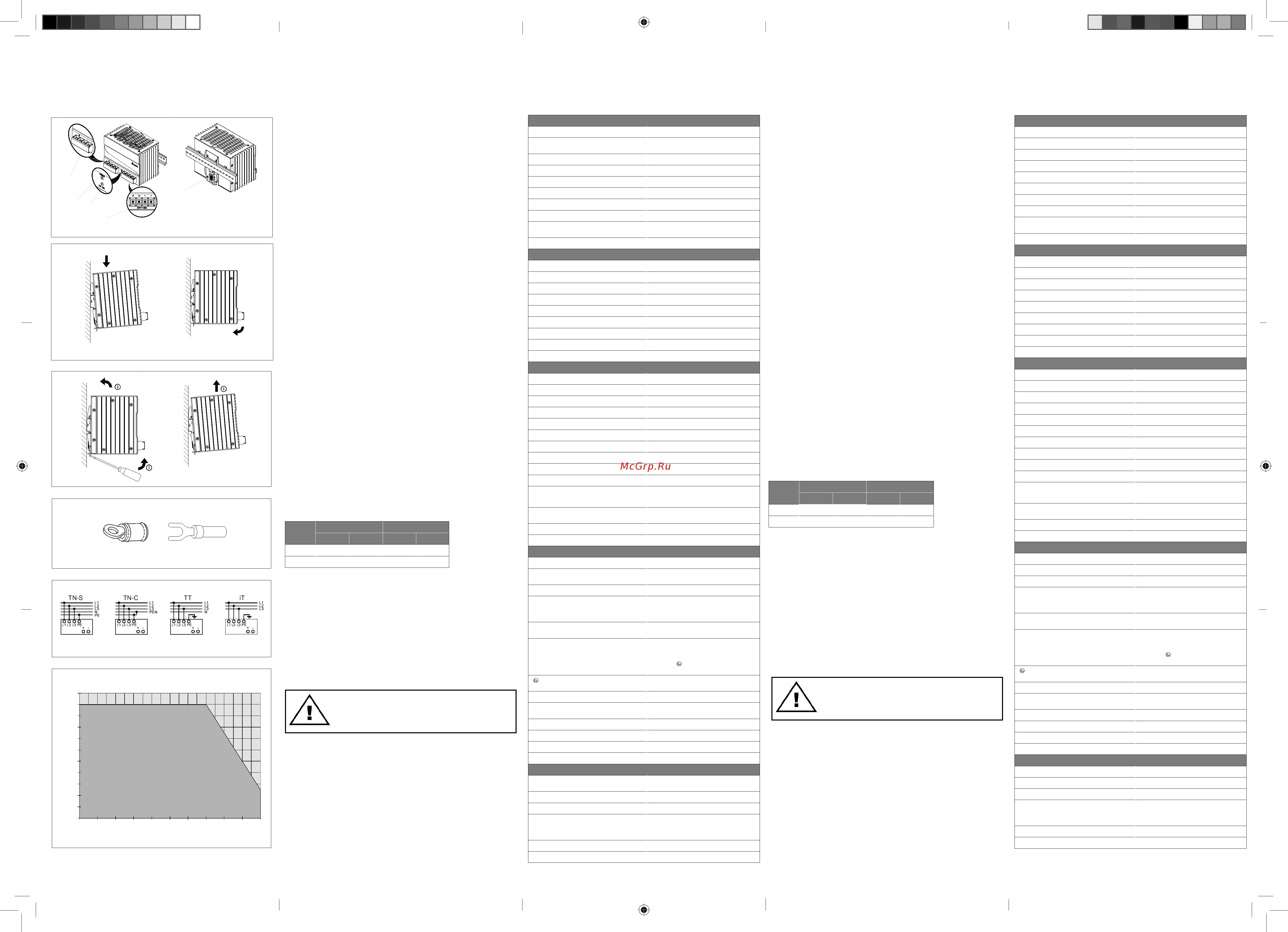
2. Gerätebeschreibung (Abb. 1)
(1) Eingangsklemmen
(2) Ausgangsklemmen
(3) Potentiometer zur Einstellung der DC-Ausgangsspannung
(4) LED für Statusanzeige „DC OK“ (grün)
(5) Universelles Montageschienensystem
3. Montage (Abb. 2)
Das Netzteil kann auf 35mm DIN-Schienen gemäß EN60715 montiert werden. Das
Gerät sollte mit den Eingangsklemmen nach unten montiert werden.
Jedes Gerät wird installationsfertig geliefert.
Einrasten des Geräts in DIN-Schiene, wie in Abb. 2 dargestellt:
1. Kippen Sie das Gerät leicht nach oben und setzen Sie es auf die DIN-Schiene
auf.
2. Kippen Sie das Gerät jetzt wieder nach unten bis zum Anschlag am unteren
Teil der Schiene.
3. Drücken Sie nun den unteren Teil des Gerätes so fest gegen die Schiene bis
das Gerät auf der Schiene einrastet.
4. Rütteln Sie leicht am Gerät, um zu überprüfen, ob es korrekt eingerastet ist.
4. Demontage (Abb. 3)
Ziehen Sie zur Demontage den Einrasthebel mit einem Schraubendreher nach unten,
wie in Abb. 3 dargestellt. Kippen Sie das Netzteil in die entgegengesetzte Richtung
nach oben, klinken Sie den Einrasthebel aus und nehmen Sie das Netzteil nach oben
von der DIN-Schiene ab.
5. Anschluss
Die Anschlussklemmen erlauben eine schnelle und einfache Verdrahtung des Geräts.
Eine Plastikabdeckung sorgt für die notwendige Isolierung der elektrischen Anschlüs-
se. Sie können exible (feindrähtige Leitung) oder feste Kabel mit folgenden Quer-
schnitten verwenden:
Um sichere und stoßfeste Anschlüsse gewährleisten zu können, sollte die Abisolier-
länge 7mm betragen.
Gemäß EN60950 / UL60950 sind für exible Kabel Aderendhülsen erforderlich.
Verwenden Sie geeignete Kupferkabel, die für Betriebstemperaturen von mindestens
75°C ausgelegt sind, um die UL-Anforderungen erfüllen zu können.
Für feindrähtige Leitungen empehlt es sich, passende Kabelschuhe zu verwenden,
um die Drähte entsprechend zu quetschen (siehe Abb. 4).
5.1. Anschluss der Eingangsklemmen (Abb. 1, Abb. 5)
Verwenden Sie die Eingangsklemmen L1, L2, L3 und PE (Schutzleiter), um den
3-phasigen 400-500Vac-Anschluss herzustellen. Abb. 5 zeigt den Anschluss an die
unterschiedlichen Netztypen. Im Fall eines Phasenausfalls ist ein uneingeschränkter
Betrieb des Gerätes bei Nennleistung noch möglich. Das Gerät verfügt über eine inter-
ne Sicherung. Es wird empfohlen für die 3 Phasen eine Vorsicherung mit 6A, 10A oder
16A Leistungsschutzschaltern zu verwenden.
1. Safety instructions
• Switch main power off before connect or disconnect the device. Danger of
explosion!
• To guarantee sufcient convection cooling, please keep a distance of 50mm
above and below the device as well as a lateral distance of 20mm to other units.
• Please note, that the enclosure of the device can become very hot depending on
the ambient temperature and load of the power supply. Risk of burns!
• Only plug in and unplug connectors when power is turned off!
• Do not introduce any objects into the unit!
• Dangerous voltage present for at least 5 minutes after disconnecting all sources of
power.
• The power supplies unit should be installed in minimum IP54 rated enclosure.
• Caution: “For use in a controlled environment”.
• Warning: Explosion Hazard - Substitution of components may impair suitability for
Class I. Division 2.
• Warning: Explosion Hazard - Do not disconnect equipment unless power has
been switched off or the area is known to be Non-Hazardous.
2. Device description (Fig. 1)
(1) Input terminal block connector
(2) Output terminal block connector
(3) DC voltage adjustment potentiometer
(4) DC OK control LED (green)
(5) Universal mounting rail system
3. Mounting (Fig. 2)
The power supply unit can be mounted on 35mm DIN rails in accordance with
EN60715. The device should be installed with input terminal block on the bottom.
Each device is delivered ready to install.
Snap on the DIN rail as shown in Fig. 2:
1. Tilt the unit slightly upwards and put it onto the DIN rail.
2. Push downwards until stopped.
3. Press against the bottom front side for locking.
4. Shake the unit slightly to ensure that it is secured.
4. Dismounting (Fig. 3)
To uninstall, pull or slide down the latch as shown in Fig. 3. Then, slide the PSU in the
opposite direction, release the latch and pull out the PSU from the rail.
5. Connection
The terminal block connectors allow easy and fast wiring. A plastic cover provides the
necessary isolation of the electric connection.
You can use exible (stranded wire) or solid cables with the following cross sections:
To secure reliable and shock proof connections, the stripping length should be 7mm.
In accordance to EN60950 / UL60950, exible cables require ferrules.
Use appropriate copper cables that are designed to sustain operating temperature of
at least 75°C or more to full UL requirements.
For stranded wires it is recommended to use suitable lug to crimp wires (see Fig. 4).
5.1. Input connection (Fig. 1, Fig. 5)
Use L1, L2, L3 and PE connections of input terminal connector (see Fig. 5) to establish
the 3 x 400-500Vac connection. Fig. 5 shows the connection to the various network
types.
In the event of a phase failure, unrestricted operation is possible with nominal capac-
ity.
The device has an internal fuse. 3 x power circuit-breakers 6A, 10A or 16A are recom-
mended as backup fuses.
(5)
(1)
(2)
(4)
(3)
Figure 2
Figure 3
Figure 1
Figure 4
Figure 5
Figure 6
Tabelle 1:
Flexibel / Starr Anzugsmoment
(mm²) (AWG) (Nm) (lb in)
(1) 0,82-2,1 18-14 1,18-1,57 10,41-13,89
(2) 3,3-5,3 12-10 1,18-1,57 10,41-13,89
Table 1:
Stranded / Solid Torque
(mm²) (AWG) (Nm) (lb in)
(1) 0.82-2.1 18-14 1.18-1.57 10.41-13.89
(2) 3.3-5.3 12-10 1.18-1.57 10.41-13.89
ATE X II3G
IE CE X
ATE X II3G
IE CE X
ATE X II3G
IE CE X
Power Derating Curve for PSU in Vertical Position
Manual_CliQ_480W3P_EOE13010010_010212.indd 1 2/1/2012 2:39:50 PM
Содержание
- 150 die se kundärspannung wird dabei so lange abgesenkt bis der sekundärseitige kurzschluss oder die überlast behoben sind 1
- 150 the secondary voltage is reduced and bounces until short circuit or over load on the secondary side has been removed 1
- Above and below the device as well as a lateral distance of 20mm to other units above and below the device as well as a lateral distance of 20mm to other units 1
- Abstand von 20mm zu anderen geräten abstand von 20mm zu anderen geräten 1
- Anleitung 1
- Anschluss der ausgangsklemmen abb 1 2 verwenden sie die schraubklemmen und um den 24vdc anschluss herzu stellen am ausgang stehen 24vdc zur verfügung die ausgangsspannung kann am potentiometer zwischen 22 und 28vdc eingestellt werden die grüne led dc ok zeigt die korrekte funktion des ausgangs an abb 1 4 das gerät verfügt über einen kurzschluss überlast und überspannungsschutz der auf 35vdc begrenzt ist 1
- Anschluss der eingangsklemmen abb 1 abb 5 verwenden sie die eingangsklemmen l1 l2 l3 und pe schutzleiter um den 3 phasigen 400 500vac anschluss herzustellen abb 5 zeigt den anschluss an die unterschiedlichen netztypen im fall eines phasenausfalls ist ein uneingeschränkter betrieb des gerätes bei nennleistung noch möglich das gerät verfügt über eine inter ne sicherung es wird empfohlen für die 3 phasen eine vorsicherung mit 6a 10a oder 16a leistungsschutzschaltern zu verwenden 1
- Anschluss die anschlussklemmen erlauben eine schnelle und einfache verdrahtung des geräts eine plastikabdeckung sorgt für die notwendige isolierung der elektrischen anschlüs se sie können flexible feindrähtige leitung oder feste kabel mit folgenden quer schnitten verwenden 1
- Auf auf 1
- Ausgangskennlinie das gerät funktioniert normal solange die netz und lastbedingungen im betriebs bereich des geräts liegen im fall eines kurzschlusses oder einer überlast fallen ausgangsspannung und strom ab bei 1
- Beachten sie dass das gehäuse des gerätes sehr heiß werden kann abhängig von der umgebungstemperatur und der last an der spannungsversorgung 1
- C device will run into thermal protection by switching off i e device will go in bouncing mode and will recover when ambient temperature is lowered or load is reduced as far as necessary to keep device in working condition 1
- C nicht herabgesetzt löst der thermische überlastschutz aus und schaltet das gerät ab das gerät bleibt dann so lange in diesem zustand bis die umgebungstemperatur oder die last soweit abge senkt wurde dass das gerät wieder im normalbetrieb arbeiten kann 1
- Connection the terminal block connectors allow easy and fast wiring a plastic cover provides the necessary isolation of the electric connection 1
- Das gerät auf der schiene einrastet das gerät auf der schiene einrastet 1
- Das netzgerät muss in einem gehäuse installiert sein das mindestens der 1
- Demontage abb 3 ziehen sie zur demontage den einrasthebel mit einem schraubendreher nach unten wie in abb 3 dargestellt kippen sie das netzteil in die entgegengesetzte richtung nach oben klinken sie den einrasthebel aus und nehmen sie das netzteil nach oben von der din schiene ab 1
- Deutsch 1
- Device description fig 1 1 input terminal block connector 2 output terminal block connector 3 dc voltage adjustment potentiometer 4 dc ok control led green 5 universal mounting rail system 1
- Die interne sicherung darf nicht vom anwender ausge tauscht werden schicken sie das gerät im fall eines defekts zur reparatur zum hersteller zurück 1
- Dismounting fig 3 to uninstall pull or slide down the latch as shown in fig 3 then slide the psu in the opposite direction release the latch and pull out the psu from the rail 1
- Drücken sie nun den unteren teil des gerätes so fest gegen die schiene bis 3 drücken sie nun den unteren teil des gerätes so fest gegen die schiene bis 1
- Each device is delivered ready to install snap on the din rail as shown in fig 2 1 tilt the unit slightly upwards and put it onto the din rail 1
- English 1
- Figure 1 1
- Figure 2 1
- Figure 3 1
- Figure 4 1
- Figure 5 1
- Figure 6 1
- For stranded wires it is recommended to use suitable lug to crimp wires see fig 4 1
- Führen sie keine objekte in das gerät ein nachdem das gerät von allen spannungsquellen getrennt wurde liegt über einen zeitraum von mindestens 5 minuten noch gefährliche spannung an dem gerät an 1
- Gemäß en60950 ul60950 sind für flexible kabel aderendhülsen erforderlich verwenden sie geeignete kupferkabel die für betriebstemperaturen von mindestens 75 c ausgelegt sind um die ul anforderungen erfüllen zu können für feindrähtige leitungen empfiehlt es sich passende kabelschuhe zu verwenden um die drähte entsprechend zu quetschen siehe abb 4 1
- Gerätebeschreibung abb 1 1 eingangsklemmen 2 ausgangsklemmen 3 potentiometer zur einstellung der dc ausgangsspannung 4 led für statusanzeige dc ok grün 5 universelles montageschienensystem 1
- In accordance to en60950 ul60950 flexible cables require ferrules use appropriate copper cables that are designed to sustain operating temperature of at least 75 c or more to fulfil ul requirements 1
- Input connection fig 1 fig 5 use l1 l2 l3 and pe connections of input terminal connector see fig 5 to establish the 3 x 400 500vac connection fig 5 shows the connection to the various network types in the event of a phase failure unrestricted operation is possible with nominal capac ity the device has an internal fuse 3 x power circuit breakers 6a 10a or 16a are recom mended as backup fuses 1
- Installation notes 1
- Jedes gerät wird installationsfertig geliefert einrasten des geräts in din schiene wie in abb 2 dargestellt 1 kippen sie das gerät leicht nach oben und setzen sie es auf die din schiene 1
- Kippen sie das gerät jetzt wieder nach unten bis zum anschlag am unteren 2 kippen sie das gerät jetzt wieder nach unten bis zum anschlag am unteren 1
- Manual_cliq_480w3p_eoe13010010_010212 indd 1 2 1 2012 2 39 50 pm 1
- Montage abb 2 das netzteil kann auf 35mm din schienen gemäß en60715 montiert werden das gerät sollte mit den eingangsklemmen nach unten montiert werden 1
- Mounting fig 2 the power supply unit can be mounted on 35mm din rails in accordance with en60715 the device should be installed with input terminal block on the bottom 1
- Only plug in and unplug connectors when power is turned off do not introduce any objects into the unit dangerous voltage present for at least 5 minutes after disconnecting all sources of power 1
- Output characteristic curve the device functions normal under operating line and load conditions in the event of a short circuit or over load the output voltage and current collapses 1
- Output connection fig 1 2 use the and screw connections to establish the 24vdc connection the output provides 24vdc the output voltage can be adjusted from 22 to 28vdc on the poten tiometer the green led dc ok displays correct function of the output fig 1 4 the device has a short circuit and overload protection and an over voltage protection limited to 35vdc 1
- Please note that the enclosure of the device can become very hot depending on the ambient temperature and load of the power supply risk of burns 1
- Power derating curve for psu in vertical position 1
- Press against the bottom front side for locking 3 press against the bottom front side for locking 1
- Push downwards until stopped 2 push downwards until stopped 1
- Rütteln sie leicht am gerät um zu überprüfen ob es korrekt eingerastet ist 4 rütteln sie leicht am gerät um zu überprüfen ob es korrekt eingerastet ist 1
- Safety instructions switch main power off before connect or disconnect the device danger of explosion 1
- Schutzklasse ip54 entspricht schutzklasse ip54 entspricht 1
- Shake the unit slightly to ensure that it is secured 4 shake the unit slightly to ensure that it is secured 1
- Sicherheitsvorschriften schalten sie die netzspannung ab bevor sie das gerät an das netz anschließen oder es vom netz trennen explosionsgefahr 1
- Technical data 1
- Technische daten 1
- Teil der schiene teil der schiene 1
- The internal fuse must not be replaced by the user in case of internal defect return the unit for inspection to the manufacturer 1
- The power supplies unit should be installed in minimum ip54 rated enclosure caution for use in a controlled environment warning explosion hazard substitution of components may impair suitability for class i division 2 1
- Thermal behavior fig 6 in the case of ambient temperatures above 50 c the output capacity has to be re duced by 2 per degree celsius increase in temperature if the output capacity is not reduced when 1
- To guarantee sufficient convection cooling please keep a distance of 50mm 1
- To secure reliable and shock proof connections the stripping length should be 7mm 1
- Um eine ausreichende konvektionskühlung zu gewährleisten halten sie ober und unterhalb des gerätes einen abstand von 50mm ein sowie einen seitlichen 1
- Um sichere und stoßfeste anschlüsse gewährleisten zu können sollte die abisolier länge 7mm betragen 1
- Verbinden und trennen sie die anschlüsse nur wenn die spannung abgeschaltet ist 1
- Verbrennungsgefahr verbrennungsgefahr 1
- Vorsicht zum einsatz nur im innenbereich warnung explosionsgefahr das austauschen von komponenten kann die eignung für klasse 1 abteilung 2 beeinträchtigen 1
- Warning explosion hazard do not disconnect equipment unless power has been switched off or the area is known to be non hazardous 1
- Warnung explosionsgefahr anlage nur dann abtrennen wenn die stromversor gung unterbrochen oder die umgebung als nicht gefährlich eingestuft wurde 1
- You can use flexible stranded wire or solid cables with the following cross sections 1
- 1 0 2 2 18 14 1 8 1 7 10 1 13 9 2
- 1 0 82 2 1 18 14 1 18 1 57 10 41 13 89 2
- 2 3 3 5 3 12 10 1 18 1 57 10 41 13 89 2
- 2 3 5 12 10 1 8 1 7 10 1 13 9 2
- Cn 安装注意事项 2
- De einbauanleitung 2
- Delta cliq power supply system 3ac 24vdc 20a 2
- Données techniques 2
- En installation notes 2
- Fr instruction d installation 2
- Français 2
- Instruction d installation 2
- Mm² awg nm lb in 2
- Tableau 1 souple rigide couple de serrage 2
- Www deltapsu com 2
- 中文 2
- 安装注意事项 2
- 技术数据及规格 2
- 表 1 多股 实心电线 扭矩 2
- 载面积 mm² 电线规范 awg nm lb in 2
Похожие устройства
- Delta Electronics DRP024V480W1AA Инструкция по эксплуатации(ENG)
- Delta Electronics DRP024V240W3AA Инструкция по эксплуатации(ENG)
- Ecotronic F2-U4 Руководство пользователя
- Ecotronic С21-U4L Руководство пользователя
- Ecotronic H1-U4LE Руководство пользователя
- Ecotronic H1-U4L Руководство пользователя
- Ecotronic M15-U4LKEM Руководство пользователя
- Delta Electronics DRP024V240W1BA Инструкция по эксплуатации(ENG)
- Delta Electronics DRP024V240W1AA Инструкция по эксплуатации(ENG)
- Ecotronic С21-U4LE Руководство пользователя
- Delta Electronics DRP024V120W3AA Инструкция по эксплуатации(ENG)
- Delta Electronics DRP024V120W1BA Инструкция по эксплуатации(ENG)
- Ecotronic С21-U4LPM Руководство пользователя
- Delta Electronics DRP024V120W1AA Инструкция по эксплуатации(ENG)
- Ecotronic M11-U4L Руководство пользователя
- Delta Electronics DRP024V060W3AA Инструкция по эксплуатации(ENG)
- Delta Electronics DRP024V060W1BA Инструкция по эксплуатации(ENG)
- Delta Electronics DRP024V060W1AZ Инструкция по эксплуатации(ENG)
- Delta Electronics DRP024V060W1AA Инструкция по эксплуатации(ENG)
- Delta Electronics DRP012V100W1AA Инструкция по эксплуатации(ENG)