
Delta Electronics DRP012V015W1AZ Инструкция по эксплуатации(ENG) онлайн
0
10
20
30
40
50
60
70
80
90
100
110
-20-100 1020304050607080
Percentage of Max Load (%)
Surrounding air temperature
(
o
C)
Figure 4
DEUTSCH
Anleitung
5.2. Anschluss der Ausgangsklemmen (Abb. 1 (2))
Verwenden Sie die Schraubklemmen „+“ und „-“, um den 12Vdc-Anschluss herzu-
stellen. Am Ausgang stehen 12Vdc zur Verfügung. Die Ausgangsspannung kann am
Potentiometer zwischen 11 und 14Vdc eingestellt werden. Die grüne LED “DC OK”
zeigt die korrekte Funktion des Ausgangs an (Abb. 1 (3)). Das Gerät verfügt über ei-
nen Kurzschluss-, Überlast- und Überspannungsschutz, der auf 17.6Vdc begrenzt ist.
5.3. Ausgangskennlinie
Das Gerät funktioniert normal, solange die Netz- und Lastbedingungen im Betriebs-
bereich des Geräts liegen. Im Fall eines Kurzschlusses oder einer Überlast fallen
Ausgangsspannung und –strom ab (bei I
Überlast
bzw. I
Kurzschluss
> I
Überstrom
(150%)). Die Se-
kundärspannung wird dabei so lange abgesenkt, bis der sekundärseitige Kurzschluss
oder die Überlast behoben sind.
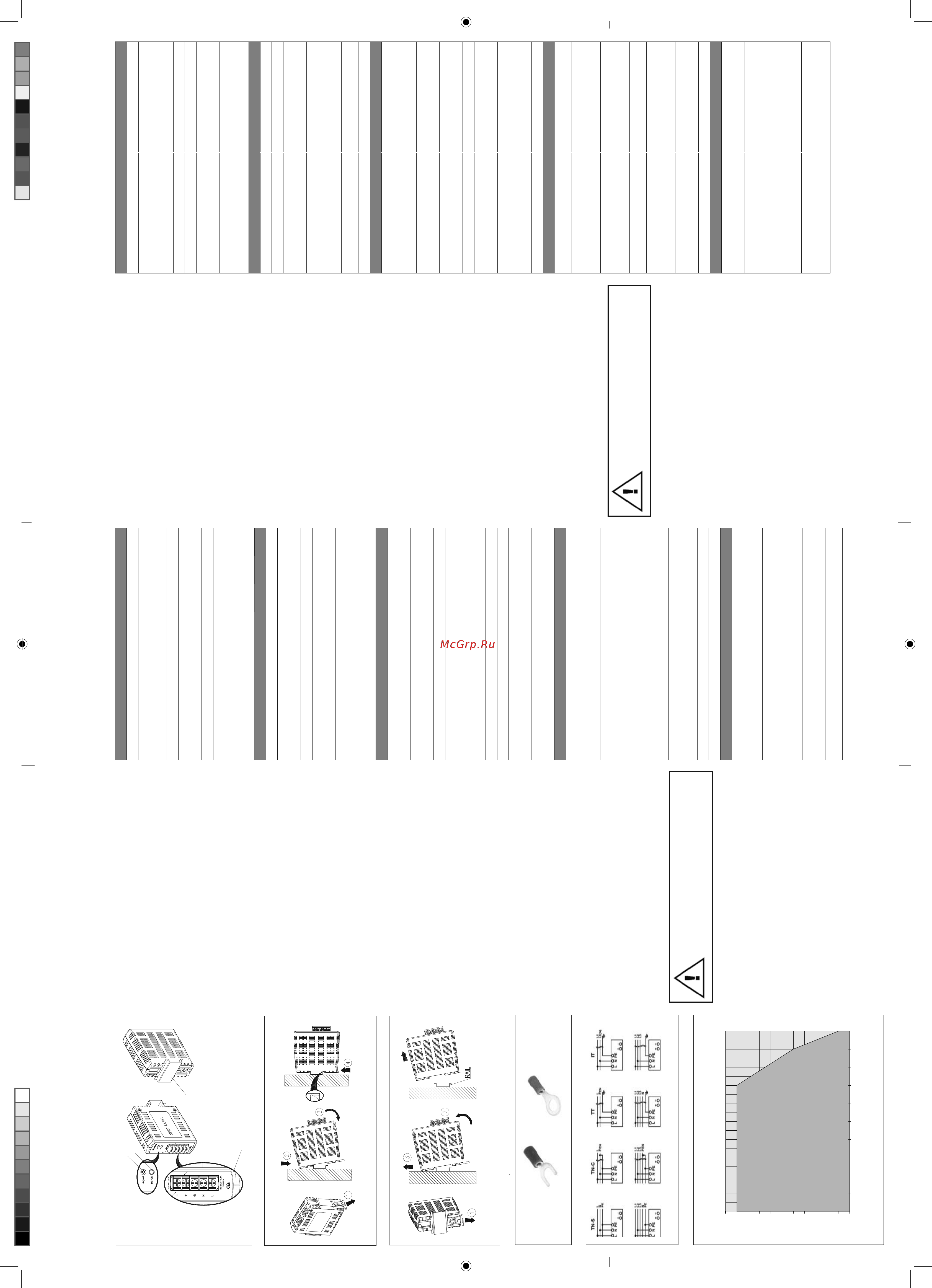
5.4. Temperaturverhalten (Abb. 6)
Beträgt die Umgebungstemperatur über +50°C, muss die Ausgangsleistung entspre-
chend dem Temperaturanstieg um 2,5% pro Celsius reduziert werden. Wird die Aus-
gangsleistung bei einer Umgebungstemperatur von > 50°C nicht herabgesetzt, löst
der thermische Überlastschutz aus und schaltet das Gerät ab. Das Gerät bleibt dann
so lange in diesem Zustand bis die Umgebungstemperatur oder die Last soweit abge-
senkt wurde, dass das Gerät wieder im Normalbetrieb arbeiten kann.
Die interne Sicherung darf nicht vom Anwender ausge-
tauscht werden. Schicken Sie das Gerät im Fall eines
Defekts zur Reparatur zum Hersteller zurück.
ENGLISH
Installation notes
5.2. Output connection (Fig. 1 (2))
Use the “+” and “-“ screw connections to establish the 12 Vdc connection. The output
provides 12Vdc. The output voltage can be adjusted from 11 to 14Vdc on the poten-
tiometer. The green LED DC OK displays correct function of the output (Fig. 1 (3)).
The device has a short circuit and overload protection and an overvoltage protection
limited to 17.6Vdc.
5.3. Output characteristic curve
The device functions normal under operating line and load conditions. In the event of
a short circuit or over load the output voltage and current collapses (I
O/L
or I
S/C
is > I
surge
(150%)). The secondary voltage is reduced and bounces until short circuit or over load
on the secondary side has been removed.
5.4. Thermal behavior (Fig. 6)
In the case of ambient temperatures above +50°C, the output capacity has to be re-
duced by 2.5% per degree Celsius increase in temperature. If the output capacity is not
reduced when T
Amb
> 50°C device will run into thermal protection by switching off i.e.
device will go in bouncing mode and will recover when ambient temperature is lowered
or load is reduced as far as necessary to keep device in working condition.
The internal fuse must not be replaced by the user.
In case of internal defect, return the unit for inspection to
the manufacturer.
ENGLISH
Technical data
Input (AC)
Nominal input voltage 100-240Vac
Voltage range 85-264Vac (DC input range 120-375Vdc)
Frequency 47-63Hz (0Hz @ DC input)
Nominal current < 0.37A @ 115Vac, < 0.22A @ 230Vac
Inrush current limitation. I
2
t (+25°C) typ. < 30A @ 115Vac, < 65A @ 230Vac
Mains buffering at nominal load (typ.) > 22ms @ 115Vac, > 110ms @ 230Vac
Turn-on time < 2.5 sec.
Internal fuse T 3.15 AH / 250V
Recommended backup fuse:
Power circuit-breaker characteristic
4A or 6A
B
Leakage current < 1mA @ 240Vac
Output (DC)
Nominal output voltage U
N
/ tolerance 12Vdc ± 2%
Adjustment range of the voltage 9GFPD[LPXPSRZHU:
Nominal current 1.25A
Derating above +50°C 2.5% / °C (> 70°C 4% / °C)
Startup with capacitive loads Max. 5,000μF
Max. power dissipation idling / nominal load approx. :
(I¿FLHQF\ > 83.5% @ 115Vac & > 83.0% @ 230Vac
Residual ripple/ peak switching (20MHz) (at nominal
values)
< 100mVpp
Parallel operation With ORing Diode
General Data
Type of housing
Plastic (PC), closed
Signals Green LED DC OK
MTBF > 300,000 hrs.
Dimensions (L x W x H) 100mm x 32mm x 100mm
Weight 0.18kg
Connection method Screw connection
Stripping length 7mm max. or use suitable lug to crimp
Operating temperature (Surrounding temperature) -20°C to +50°C
Storage temperature -25°C to +85°C
Humidity at +25°C, no condensation < 95% RH
Vibration (non-operating)
10 to 150Hz, 0.35mm acc. 50m / s², single
amplitude (5G max.) for 90 min. in each X, Y & Z
directions, in acc. with IEC60068-2-6
Pollution degree 2
Climatic class 3K3 according to EN60721
&HUWL¿FDWLRQDQG6WDQGDUGV
Electrical equipments of machines
TUV Bauart to IEC60204-1
(over voltage category III)
Electronic equipment for use in electrical power
installations
TUV Bauart to EN50178 / IEC62103
Safety entry low voltage PELV (EN60204), SELV (EN60950)
Electrical safety (of information technology equipment)
TUV Bauart EN60950-1,
UL/C-UL recognized to UL60950-1, CSA C22.2
No. 60950-1,
CB scheme to IEC60950-1
Industrial control equipment
UL / C-UL listed UL 508 and CSA C22.2 No.
107.1-01; CSA to CSA C22.2 No. 107.1-01
Protection against electric shock DIN57100-410
CE
In conformance with EMC directive 2004/108/EC
and low voltage directive 2006/95/EC
EMC for ITE EN55022, EN61000-3-2, EN61000-3-3, EN55024
EMC for Industrial EN55011, EN61000-6-2
Limitation of mains harmonic currents n. a.
Safety and Protection
Transient surge voltage protection
VARISTOR
Current limitation at short-circuits approx. I
surge
= 150% of Po
max
typically
Surge voltage protection against internal surge
voltages
Yes
Isolation voltage:
Input / output (type test/routine test)
Input / PE (type test/routine test)
Output / PE (type test/routine test)
4.0KVac / 3.0KVac
1.5KVac / 1.5KVac
1.5KVac / 0.5KVac
Protection degree IPX0
Safety class Class I with PE connection
Shock (in all directions)
30G (300m/s²) in all directions according to
IEC60068-2-27
DEUTSCH
Technische Daten
Eingangskennwerte (AC)
Nennspannung 100-240Vac
Spannungsbereich
85-264Vac(DC-Eingangsspannungsbereich
120-375Vdc)
Frequenzbereich 47-63Hz (0Hz bei DC Eingangsspannung)
Nennstrom < 0,37A bei 115Vac, < 0,22A bei 230Vac
Einschaltstrombegrenzung I²t (+25°C) typ. < 30A bei 115Vac, < 65A bei 230Vac
Netzausfallüberbrückung bei Nennlast (typ.) > 22ms bei 115Vac, > 110ms bei 230Vac
Einschaltzeit < 2,5 sec.
Interne Sicherung T 3.15 AH / 250V
Empfohlene Vorsicherung:
Auslösecharakteristik Leistungsschalter
4A oder 6A
B
Ableitstrom < 1mA bei 240Vac
Ausgangskennwerte (DC)
Nennausgangsspannung U
N
/ Toleranz 12Vdc ± 2%
Einstellbereich der Ausgangsspannung 9GFPD[/HLVWXQJ:
Nennstrom 1,25A
Derating (Leistungsherabsetzung) ab T
amb
> +50°C 2,5% / °C (> 70°C 4% / °C)
Anlaufen bei Kapazitiven Lasten Max. 5.000μF
Max. Verlustleistung Leerlauf/Nennlast :
Wirkungsgrad > 83,5% bei 115Vac & > 83,0% bei 230Vac
Restwelligkeit / Schaltspitzen (20MHz) (bei Nenn-
werten)
< 100mVpp
Parallelschaltbarkeit mit ORing Diode
Allgemeine Kennwerte
Gehäusetyp
Plastik (PC), geschlossen
Statusanzeige Grüne LED „DC OK“
MTBF (mittlere Betriebszeit zwischen Ausfällen) > 300.000 Std.
Abmessungen (B x H x T) 100mm x 32mm x 100mm
Gewicht 0,18kg
Art der Anschlussklemme Schraubanschluss
Abisolierlänge
7mm max. oder geeigneter Kabelschuh zum
Quetschen
Betriebstemperaturbereich (Umgebungstemperatur) -20°C bis +50°C
Lagertemperaturbereich -25°C bis +85°C
Luftfeuchte bei +25°C, keine Betauung < 95% relative Luftfeuchte
Vibration (außer Betrieb)
10 bis 150Hz, Beschl. 50m / s², 0,35mm
Einzelamplitude (5g max.) für 90 min. in X, Y & Z
Richtung, gemäß IEC60068-2-6
Verschmutzungsgrad 2
Klimaklasse 3K3 gemäß EN60721
=HUWL¿]LHUXQJXQG1RUPHQ
Elektrische Ausrüstung von Maschinen
TUV Bauart IEC60204-1
(Überspannungskategorie III)
Ausrüstung von Starkstromanlagen mit elektronischen
Betriebsmitteln
TUV Bauart EN50178 / IEC62103
Schutzkleinspannung PELV (EN60204), SELV (EN60950)
Elektrische Sicherheit (von Einrichtungen der Infor-
mationstechnik)
TUV-Bauart EN60950-1,
UL/C-UL zugelassen UL60950-1, CSA C22.2
No. 60950-1,
CB Schema gemäß IEC60950-1
Industrielle Regeleinrichtungen
UL / C-UL gemäß UL 508 und CSA C22.2 No.
107.1-01; CSA nach CSA C22.2 No. 107.1-01
Schutz gegen elektrischen Schlag DIN57100-410
EC
In Konformität zur EMV-Richtlinie 2004/108/EC
und Niederspannungsrichtlinie 2006/95/EC
EMV für ITE EN55022, EN61000-3-2, EN61000-3-3, EN55024
EMV für Industrie EN55011, EN61000-6-2
Begrenzung der Netzoberschwingungen n. a.
Sicherheit und Schutzeinrichtungen
Überspannungsschutz gegen transiente
Überspannungen
VARISTOR
Strombegrenzung bei Kurzschluss I
Überstrom
= 150% der max. Ausgangsleistung
Überspannungsschutz gegen interne Überspannungen Ja
Isolationsspannung
Eingang / Ausgang (Typprüfung/Stückprüfung)
Eingang / Schutzleiter (Typprüfung/Stückprüfung)
Ausgang / Schutzleiter (Typprüfung/Stückprüfung)
4,0KVac / 3,0KVac
1,5KVac / 1,5KVac
1,5KVac / 0,5KVac
Schutzart IPX0
Schutzklasse Klasse I mit Schutzleiteranschluss
Stoßfestigkeit (in alle Richtungen)
30g (300m/s²) in alle Richtungen gemäß
IEC60068-2-27
(1)
(4)
(2)
(3)
Figure 2
Figure 3
1. Sicherheitsvorschriften
6FKDOWHQ6LHGLH1HW]VSDQQXQJDEEHYRU6LHGDV*HUlWDQGDV1HW]DQVFKOLHHQ
oder es vom Netz trennen. Explosionsgefahr!
8PHLQHDXVUHLFKHQGH.RQYHNWLRQVNKOXQJ]XJHZlKUOHLVWHQKDOWHQ6LHREHU
und unterhalb des Gerätes einen Abstand von 50mm ein sowie einen seitlichen
Abstand von 20mm zu anderen Geräten.
%HDFKWHQ6LHGDVVGDV*HKlXVHGHV*HUlWHVVHKUKHLZHUGHQNDQQDEKlQJLJ
von der Umgebungstemperatur und der Last an der Spannungsversorgung.
Verbrennungsgefahr!
9HUELQGHQXQGWUHQQHQ6LHGLH$QVFKOVVHQXUZHQQGLH6SDQQXQJDEJHVFKDOWHW
ist!
)KUHQ6LHNHLQH2EMHNWHLQGDV*HUlWHLQ
1DFKGHPGDV*HUlWYRQDOOHQ6SDQQXQJVTXHOOHQJHWUHQQWZXUGHOLHJWEHUHLQHQ
Zeitraum von mindestens 5 Minuten noch gefährliche Spannung an dem Gerät an.
8PYRU=XJULIIDXIHOHNWULVFKH7HLOH]XVFKW]HQPVVHQDOOH7HLOHGHV1HW]WHLOV
eingebaut sein (bzw. in einem Schutzgehäuse installiert werden).
2. Gerätebeschreibung (Abb. 1)
(1) Eingangs- und Ausgangsklemmen
(2) Potentiometer zur Einstellung der DC-Ausgangsspannung
(3) LED für Statusanzeige „DC OK“ (grün)
(4) Universelles Montageschienensystem
3. Montage (Abb. 2)
Das Netzteil kann auf 35mm DIN-Schienen gemäß EN60715 montiert werden. Das
Gerät sollte waagerecht mit den Eingangsklemmen nach unten montiert werden.
Jedes Gerät wird installationsfertig geliefert.
Einrasten des Geräts in DIN-Schiene, wie in Abb. 2 dargestellt:
1. Ziehen Sie den Einrasthebel für die DIN-Schiene nach UNTEN.
2. Kippen Sie das Gerät leicht nach oben, setzen Sie es auf die DIN-Schiene auf
und kippen das Gerät bis zum Anschlag am unteren Teil der Schiene wieder
nach unten.
3. Drücken Sie nun den unteren Teil des Gerätes so fest gegen die Schiene bis
das Gerät auf der Schiene einrastet.
4. Drücken Sie den Einrasthebel wieder hinein, um das Gerät auf der DIN-Schie-
ne zu verriegeln.
4. Demontage (Abb. 3)
Zur Demontage,
1. Ziehen Sie den Einrasthebel für die DIN-Schiene nach UNTEN.
2. Kippen Sie das Gerät nach oben und entfernen zunächst den unteren Teil des
Geräts von der DIN-Schiene.
3. Nehmen Sie das Gerät nun nach oben komplett von der DIN-Schiene ab.
5. Anschluss
Die Anschlussklemmen erlauben eine schnelle und einfache Verdrahtung des Geräts.
Eine Plastikabdeckung sorgt für die notwendige Isolierung der elektrischen Anschlüs-
se.
6LHN|QQHQÀH[LEOHIHLQGUlKWLJH/HLWXQJRGHUIHVWH.DEHOPLWHLQHP4XHUVFKQLWWYRQ
0,32-2,1mm² (AWG 22-14) und einem Anzugsmoment von 0,79Nm (7,0lb in) verwen-
den. Um sichere und stoßfeste Anschlüsse gewährleisten zu können, sollte die Abiso-
OLHUOlQJHPPEHWUDJHQ
*HPl(18/VLQGIUÀH[LEOH.DEHO$GHUHQGKOVHQHUIRUGHUOLFK
Verwenden Sie geeignete Kupferkabel, die für Betriebstemperaturen von mindestens
75°C ausgelegt sind, um die UL-Anforderungen erfüllen zu können.
)UIHLQGUlKWLJH/HLWXQJHQHPS¿HKOWHVVLFKSDVVHQGH.DEHOVFKXKH]XYHUZHQGHQ
um die Drähte entsprechend zu quetschen (siehe Abb. 4).
5.1. Anschluss der Eingangsklemmen (Abb. 1, Abb. 5)
Verwenden Sie die Eingangsklemmen L, N und PE (Schutzleiter), um den 100-240Vac-
Anschluss herzustellen. Das Gerät kann ebenfalls an zwei der Phasenleiter des Dreh-
stromnetzes (TN-, TT- oder IT-Systeme) mit einer Nennspannung von 100Vac-240Vac
angeschlossen werden. Das Gerät verfügt über eine interne Sicherung. Es wird emp-
fohlen einen 4A oder 6A Leistungsschutzschalter als Vorsicherung zu verwenden.
1. Safety instructions
6ZLWFKPDLQSRZHURIIEHIRUHFRQQHFWRUGLVFRQQHFWWKHGHYLFH'DQJHURI
explosion!
7RJXDUDQWHHVXI¿FLHQWFRQYHFWLRQFRROLQJSOHDVHNHHSDGLVWDQFHRIPP
above and below the device as well as a lateral distance of 20mm to other units.
3OHDVHQRWHWKDWWKHHQFORVXUHRIWKHGHYLFHFDQEHFRPHYHU\KRWGHSHQGLQJRQ
the ambient temperature and load of the power supply. Risk of burns!
2QO\SOXJLQDQGXQSOXJFRQQHFWRUVZKHQSRZHULVWXUQHGRII
'RQRWLQWURGXFHDQ\REMHFWVLQWRWKHXQLW
'DQJHURXVYROWDJHSUHVHQWIRUDWOHDVWPLQXWHVDIWHUGLVFRQQHFWLQJDOOVRXUFHVRI
power.
7RSURWHFWDJDLQVWDFFHVVWROLYHSDUWVWKH368PXVWEHEXLOWLQPXVWEHLQVWDOOHG
in a protective enclosure).
2. Device description (Fig. 1)
(1) Input & output terminal block connector
(2) DC voltage adjustment potentiometer
(3) DC OK control LED (green)
(4) Universal mounting rail system
3. Mounting (Fig. 2)
The power supply unit can be mounted on 35mm DIN rails in accordance with
EN60715. The device should be installed horizontally with input terminal blocks on
the bottom.
Each device is delivered ready to install.
Snap on the DIN rail as shown in Fig. 2:
1. Pull the unit’s DIN rail latch OUT.
2. Tilt the unit slightly upwards, hook the top end onto the DIN rail and push down
wards until stopped.
3. Position the bottom front end against the DIN rail.
4. Push the unit’s latch DIN rail IN to lock.
4. Dismounting (Fig. 3)
To uninstall,
1. Pull the unit’s DIN rail latch OUT.
2. Tilt the bottom part of the unit out.
3. Push the unit up and pull out from the DIN rail.
5. Connection
The terminal block connectors allow easy and fast wiring. A plastic cover provides the
necessary isolation of the electric connection.
<RX FDQXVHÀH[LEOHVWUDQGHG ZLUHRUVROLGFDEOHV ZLWKFURVVVHFWLRQPPð
(AWG 22-14) and torque of 0.79Nm (7.0lb in). To secure reliable and shock proof con-
nections, the stripping length should not exceed 7mm.
,QDFFRUGDQFHWR(18/ÀH[LEOHFDEOHVUHTXLUHIHUUXOHV
Use appropriate copper cables that are designed to sustain operating temperature of
DWOHDVW&RUPRUHWRIXO¿O8/UHTXLUHPHQWV
For stranded wires it is recommended to use suitable lug to crimp wires (see Fig. 4).
5.1. Input connection (Fig. 1, Fig. 5)
Use L, N and PE connections of input terminal connector (see Fig. 1 (1)) to establish
the 100-240Vac connection.
The device can also be connected to two of the phase conductor of three- phase sys-
tems ( TN,TT or IT systems) with nominal voltages of 100Vac-240Vac.
The device has an internal fuse. 4A or 6A power circuit breakers are recommended
as backup fuses.
Figure 6
Figure 5
Figure 1
Power Derating Curve for PSU
Manual_CliQ_12V_15W1P_E0E11010156_141111.indd 1 11/14/2011 10:23:23 AM
Содержание
- 0 32 2 1mm² awg 22 14 und einem anzugsmoment von 0 79nm 7 0lb in verwen den um sichere und stoßfeste anschlüsse gewährleisten zu können sollte die abiso 1
- 150 die se kundärspannung wird dabei so lange abgesenkt bis der sekundärseitige kurzschluss oder die überlast behoben sind 1
- 150 the secondary voltage is reduced and bounces until short circuit or over load on the secondary side has been removed 1
- Anleitung 1
- Anschluss der ausgangsklemmen abb 1 2 verwenden sie die schraubklemmen und um den 12vdc anschluss herzu stellen am ausgang stehen 12vdc zur verfügung die ausgangsspannung kann am potentiometer zwischen 11 und 14vdc eingestellt werden die grüne led dc ok zeigt die korrekte funktion des ausgangs an abb 1 3 das gerät verfügt über ei nen kurzschluss überlast und überspannungsschutz der auf 17 vdc begrenzt ist 1
- Anschluss der eingangsklemmen abb 1 abb 5 verwenden sie die eingangsklemmen l n und pe schutzleiter um den 100 240vac anschluss herzustellen das gerät kann ebenfalls an zwei der phasenleiter des dreh stromnetzes tn tt oder it systeme mit einer nennspannung von 100vac 240vac angeschlossen werden das gerät verfügt über eine interne sicherung es wird emp fohlen einen 4a oder 6a leistungsschutzschalter als vorsicherung zu verwenden 1
- Anschluss die anschlussklemmen erlauben eine schnelle und einfache verdrahtung des geräts eine plastikabdeckung sorgt für die notwendige isolierung der elektrischen anschlüs se 1
- Ausgangskennlinie das gerät funktioniert normal solange die netz und lastbedingungen im betriebs bereich des geräts liegen im fall eines kurzschlusses oder einer überlast fallen ausgangsspannung und strom ab bei 1
- Awg 22 14 and torque of 0 9nm 7 lb in to secure reliable and shock proof con nections the stripping length should not exceed 7mm 1
- C device will run into thermal protection by switching off i e device will go in bouncing mode and will recover when ambient temperature is lowered or load is reduced as far as necessary to keep device in working condition 1
- C nicht herabgesetzt löst der thermische überlastschutz aus und schaltet das gerät ab das gerät bleibt dann so lange in diesem zustand bis die umgebungstemperatur oder die last soweit abge senkt wurde dass das gerät wieder im normalbetrieb arbeiten kann 1
- Connection the terminal block connectors allow easy and fast wiring a plastic cover provides the necessary isolation of the electric connection 1
- Demontage abb 3 zur demontage 1 ziehen sie den einrasthebel für die din schiene nach unten 2 kippen sie das gerät nach oben und entfernen zunächst den unteren teil des geräts von der din schiene 3 nehmen sie das gerät nun nach oben komplett von der din schiene ab 1
- Deutsch 1
- Device description fig 1 1 input output terminal block connector 2 dc voltage adjustment potentiometer 3 dc ok control led green 4 universal mounting rail system 1
- Die interne sicherung darf nicht vom anwender ausge tauscht werden schicken sie das gerät im fall eines defekts zur reparatur zum hersteller zurück 1
- Dismounting fig 3 to uninstall 1 pull the unit s din rail latch out 2 tilt the bottom part of the unit out 3 push the unit up and pull out from the din rail 1
- Each device is delivered ready to install snap on the din rail as shown in fig 2 1 pull the unit s din rail latch out 2 tilt the unit slightly upwards hook the top end onto the din rail and push down wards until stopped 3 position the bottom front end against the din rail 4 push the unit s latch din rail in to lock 1
- English 1
- Figure 1 1
- Figure 4 1
- Figure 5 1
- Figure 6 1
- For stranded wires it is recommended to use suitable lug to crimp wires see fig 4 1
- Gerätebeschreibung abb 1 1 eingangs und ausgangsklemmen 2 potentiometer zur einstellung der dc ausgangsspannung 3 led für statusanzeige dc ok grün 4 universelles montageschienensystem 1
- Input connection fig 1 fig 5 use l n and pe connections of input terminal connector see fig 1 1 to establish the 100 240vac connection 1
- Installation notes 1
- Jedes gerät wird installationsfertig geliefert einrasten des geräts in din schiene wie in abb 2 dargestellt 1
- Manual_cliq_12v_15w1p_e0e11010156_141111 indd 1 11 14 2011 10 23 23 am 1
- Montage abb 2 das netzteil kann auf 35mm din schienen gemäß en60715 montiert werden das gerät sollte waagerecht mit den eingangsklemmen nach unten montiert werden 1
- Mounting fig 2 the power supply unit can be mounted on 35mm din rails in accordance with en60715 the device should be installed horizontally with input terminal blocks on the bottom 1
- Output characteristic curve the device functions normal under operating line and load conditions in the event of a short circuit or over load the output voltage and current collapses 1
- Output connection fig 1 2 use the and screw connections to establish the 12 vdc connection the output provides 12vdc the output voltage can be adjusted from 11 to 14vdc on the poten tiometer the green led dc ok displays correct function of the output fig 1 3 the device has a short circuit and overload protection and an overvoltage protection limited to 17 vdc 1
- Power derating curve for psu 1
- Safety instructions explosion above and below the device as well as a lateral distance of 20mm to other units the ambient temperature and load of the power supply risk of burns power in a protective enclosure 1
- Sicherheitsvorschriften oder es vom netz trennen explosionsgefahr und unterhalb des gerätes einen abstand von 50mm ein sowie einen seitlichen abstand von 20mm zu anderen geräten von der umgebungstemperatur und der last an der spannungsversorgung verbrennungsgefahr ist zeitraum von mindestens 5 minuten noch gefährliche spannung an dem gerät an eingebaut sein bzw in einem schutzgehäuse installiert werden 1
- Technical data 1
- Technische daten 1
- The device can also be connected to two of the phase conductor of three phase sys tems tn tt or it systems with nominal voltages of 100vac 240vac 1
- The device has an internal fuse 4a or 6a power circuit breakers are recommended as backup fuses 1
- The internal fuse must not be replaced by the user in case of internal defect return the unit for inspection to the manufacturer 1
- Thermal behavior fig 6 in the case of ambient temperatures above 50 c the output capacity has to be re duced by 2 per degree celsius increase in temperature if the output capacity is not reduced when 1
- Um die drähte entsprechend zu quetschen siehe abb 4 1
- Use appropriate copper cables that are designed to sustain operating temperature of 1
- Verwenden sie geeignete kupferkabel die für betriebstemperaturen von mindestens 75 c ausgelegt sind um die ul anforderungen erfüllen zu können 1
- Ziehen sie den einrasthebel für die din schiene nach unten 1 ziehen sie den einrasthebel für die din schiene nach unten 2 kippen sie das gerät leicht nach oben setzen sie es auf die din schiene auf und kippen das gerät bis zum anschlag am unteren teil der schiene wieder nach unten 3 drücken sie nun den unteren teil des gerätes so fest gegen die schiene bis das gerät auf der schiene einrastet 4 drücken sie den einrasthebel wieder hinein um das gerät auf der din schie ne zu verriegeln 1
- De einbauanleitung en installation notes fr instruction d installation cn 2
- Delta cliq power supply system 1ac 12vdc 1 5a 2
- Données techniques 2
- Français 2
- Instruction d installation 2
- Www deltapsu com 2
Похожие устройства
- Gretti NR-100C Руководство пользователя
- Delta Electronics PMC-DSPV100W1A Инструкция по эксплуатации(ENG)
- Delta Electronics PMC-24V300W1BA Инструкция по эксплуатации(ENG)
- Delta Electronics PMC-24V150W1AA Инструкция по эксплуатации(ENG)
- Gretti NR-101 Руководство пользователя
- Gretti NR-120 Руководство пользователя
- Gretti NR-130 Руководство пользователя
- Gretti TS-206 Руководство пользователя
- Gretti TS-206HB Руководство пользователя
- Gretti TS-206SHD Руководство пользователя
- Gretti TS-206SHD Руководство пользователя, в.2
- Elpumps VB25/800 Руководство по эксплуатации
- Elpumps VB25/1300 Руководство по эксплуатации
- Elpumps VB25/1300B Руководство по эксплуатацтии
- Elpumps VB25/1300 INOX Руководство по эксплуатации
- Elpumps VBP25/1300 INOX Руководство по эксплуатации
- Elpumps VB50/1500B Руководство по эксплуатации
- Elpumps CT2274W Руководство по эксплуатации
- Elpumps CT2274 Руководство пользователя
- Elpumps CT3274 Руководство по эксплуатации