
Omron VZA24P0BAA Инструкция по эксплуатации онлайн
M('''
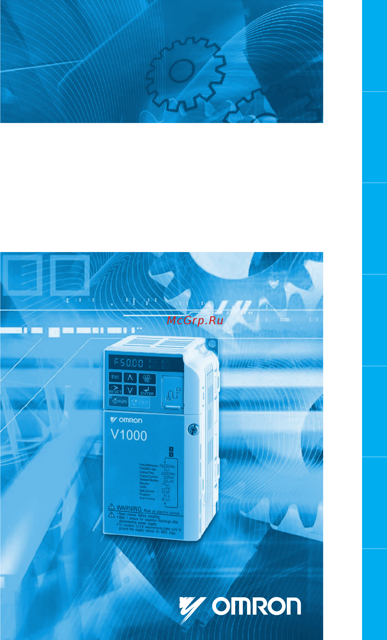
Compact Current Vector Inverter
Model: VZA
200V Class Single-phase 0.12 to 4.0/5.5 kW
200V Class 3-phase 0.12 to 15/18.5 kW
400V Class 3-phase 0.2 to 15/18.5 kW
HL@:BJK8IK>L@;<
:Xk%Ef%
@-.<$<E$'(
Note: Specifications subject to change without notice.
Cat. No. I67E-EN-01
M8I@JG<<;M.@G-, Hl`ZbJkXik>l`[\
Cat. No. I67E-EN-01
In the event that the end user of this product is to be the military and said product is to be employed in any
weapons systems or the manufacture thereof, the export will fall under the relevand regulations as stipulated in the
Foreign Exchange and Foreign Trade Regulations. Therefore, be sure to follow all procedures and submit all relevant
documentation according to any and all rules, regulations and laws may apply.
Specifications are subject to change without notice for ongoing product modifications and improvements.
© 2007 OMRON Yaskawa Motion Control. All rights reserved.
Manufacturer
Y
ASKAWA
YASKAWA ELECTRIC CORPORATION
OMRON EUROPE B.V.
Wegalaan 67-69, NL-2132 JD, Hoofddorp, The Netherlands.
Tel: +31 23 568 13 00 Fax: +31 23 568 13 88 www.omron-industrial.com
Austria
Tel: +43 (0) 2236 377 800
www.omron.at
Belgium
Tel: +32 (0) 2 466 24 80
www.omron.be
Czech Republic
Tel: +420 234 602 602
www.omron.cz
Denmark
Tel: +45 43 44 00 11
www.omron.dk
Finland
Tel: +358 (0) 207 464 200
www.omron.fi
France
Tel: +33 1 56 63 70 00
www.omron.fr
Germany
Tel: +49 (0) 2173 680 00
www.omron.de
Hungary
Tel: +36 1 399 30 50
www.omron.hu
Italy
Tel: +39 02 32 681
www.omron.it
Middle East & Africa
Tel: +31 (0) 23 568 11 00
www.omron-industrial.com
Netherlands
Tel: +31 (0) 23 568 11 00
www.omron.nl
Norway
Tel: +47 22 65 75 00
www.omron.no
Poland
Tel: +48 (0) 22 645 78 60
www.omron.com.pl
Portugal
Tel: +351 21 942 94 00
www.omron.pt
Russia
Tel: +7 495 648 94 50
www.omron.ru
Spain
Tel: +34 913 777 900
www.omron.es
Sweden
Tel: +46 (0) 8 632 35 00
www.omron.se
Switzerland
Tel: +41 (0) 41 748 13 13
www.omron.ch
Turkey
Tel: +90 216 474 00 40 Pbx
www.omron.com.tr
United Kingdom
Tel: +44 (0) 870 752 08 61
www.omron.co.uk
EnglishDeutschEspañolFrançais
0YCCÅÃÄ
Türkçe
Italiano
Содержание
- Compact current vector inverter model vza 200v class single phase 0 2 to 4 5 kw 200v class 3 phase 0 2 to 15 18 kw 400v class 3 phase 0 to 15 18 kw 1
- English deutsch español français türkçe italiano 1
- V1000 quick start guide 1
- English 2
- Quick start guide 2
- General warnings 3
- Safety instructions and general warnings 3
- Electrical shock hazard 4
- English 4
- Safety instructions and general warnings 4
- Safety warnings 4
- Sudden movement hazard 4
- Burn hazard 5
- Caution 5
- Crush hazard 5
- Fire hazard 5
- Safety instructions and general warnings 5
- Warning 5
- English 6
- Equipment hazard 6
- Notice 6
- Safety instructions and general warnings 6
- Precautions for ce low voltage directive compliance 7
- Precautions for ul cul standards compliance 7
- Precautions for using the safe disable function 7
- Safety instructions and general warnings 7
- English 8
- Installation environment 8
- Mechanical installation 8
- Upon receipt 8
- Always install the drive in an upright posi tion leave space around the unit for proper cooling as shown in the figure on the right note several units can be installed closer together than shown in the figure by using side by side mounting for details please refer to the instruction manual 9
- Dimensions 9
- Installation orientation and spacing 9
- Mechanical installation 9
- Electrical installation 10
- English 10
- Electrical installation 11
- I67e en v1000 quick start guide 11
- Main circuit use the fuses and line filters listed up in the table below when wiring the main cir cuit make sure not to exceed the given tightening torque values 11
- Tighten the main circuit terminals using the torque values provided by the table be low 11
- Wiring specification 11
- Control circuit the control terminal board is equipped with screwless terminals always use wires within the specification listed below for safe wiring it is recommended to use solid wires or flexible wires with ferrules the stripping length respectively ferrule length should be 8 mm 12
- Electrical installation 12
- Emc filter installation 12
- English 12
- This drive has been tested in accordance with european standards en61800 3 in order to comply to the emc standards wire the main circuit as described below 1 install an appropriate emc noise filter to the input side see the list above or refer to the instruction manual for details 2 place the drive and emc noise filter in the same enclosure 3 use braided shield cable for the drive and motor wiring 4 remove any paint or dirt from ground connections for minimal ground impedance 5 install an ac reactor at drives smaller than 1 kw for compliance with the en61000 3 2 refer to the instruction manual or contact your supplier for details 12
- Electrical installation 13
- Main and control circuit wiring 13
- Electrical installation 14
- English 14
- For external control power supply use a ul listed class 2 power supply use twisted pair or shielded twisted pair cables for control circuits to prevent op erating faults ground the cable shields with the maximum contact area of the shield and ground cable shields should be grounded on both cable ends 14
- I67e en v1000 quick start guide 14
- Main circuit terminals 14
- Main circuit terminals the figure below shows the control circuit terminal arrangement the drive is equipped with screwless terminals 14
- There are three dip switches s1 to s3 located on the terminal board 14
- Control circuit terminals 15
- Electrical installation 15
- I67e en v1000 quick start guide 15
- Notice the terminals hc h1 h2 are used for the safe disable function which cuts the output voltage in less than 1 ms if at least one of the inputs h1 or h2 is opened it is designed in accordance with the en954 1 safety category 3 and en61508 sil2 it and can be utilized to perform a safe stop as defined by the en60204 1 stop category 0 do not remove the wire link between hc h1 or h2 unless the safe disable function is used 15
- English 16
- Keypad operation 16
- Led operator and keys 16
- I67e en v1000 quick start guide 17
- Keypad operation 17
- Menu structure and modes 17
- The following illustration explains the operator keypad menu structure 17
- Drive setup procedure 18
- English 18
- Start up 18
- Auto tuning automatically sets up the motor data relevant drive parameters three different modes are supported 19
- Auto tuning t1 19
- Auto tuning t1 oo 19
- Before turning on the power supply make sure all wires are connected properly make sure no screws loose wire ends or tools are left in the drive after turning the power on the drive mode display should appear and no fault or alarm should be displayed 19
- Caution 19
- Control mode selection a1 02 19
- Power on 19
- Start up 19
- There are three control modes available select the control mode that best suits the applications the drive will control 19
- English 20
- For auto tuning enter the auto tuning menu and perform the steps shown in the fig ure below the number of name plate data to be entered depends on the selected type of auto tuning this example shows rotational auto tuning 20
- I67e en v1000 quick start guide 20
- If auto tuning can not be performed for some reason no load operation impossible etc then set up the maximum frequency and voltage in the e1 parameters and enter the motor data manually into the e2 parameters 20
- Notice the safe disable inputs must be closed during auto tuning 20
- Start up 20
- I o setup 21
- Reference and run source 21
- Start up 21
- English 22
- Frequency reference and acceleration deceleration times 22
- Start up 22
- Test run 22
- I67e en v1000 quick start guide 23
- Parameter table 23
- This parameter table shows the most important parameters default settings are bold type refer to the instruction manual for a complete list of parameters 23
- English 24
- I67e en v1000 quick start guide 24
- Parameter table 24
- I67e en v1000 quick start guide 25
- Parameter table 25
- English 26
- I67e en v1000 quick start guide 26
- Parameter table 26
- I67e en v1000 quick start guide 27
- Parameter table 27
- English 28
- General fault and alarms 28
- Troubleshooting 28
- I67e en v1000 quick start guide 29
- Troubleshooting 29
- An operator programming error ope occurs when an inapplicable parameter is set or an individual parameter setting is inappropriate when an ope error is dis played press the enter button to display u1 18 ope fault constant this monitor will display the parameter that is causing the ope error 30
- English 30
- Operator programing errors 30
- Troubleshooting 30
- Auto tuning errors 31
- I67e en v1000 quick start guide 31
- Troubleshooting 31
- Deutsch 32
- Kurzanleitung 32
- Allgemeine warnhinweise 33
- Sicherheitsanweisungen und allgemeine warnhinweise 33
- Englisch 34
- Gefahr eines stromschlags 34
- Sicherheitsanweisungen und allgemeine warnhinweise 34
- Sicherheitswarnungen 34
- Achtung 35
- Feuergefahr 35
- Gefahr durch plötzliche bewegung 35
- Gefahr von quetschungen 35
- Gefahr von verbrennungen 35
- Sicherheitsanweisungen und allgemeine warnhinweise 35
- Vorsicht 35
- Englisch 36
- Gefahr für die ausrüstung 36
- Hinweis 36
- Sicherheitsanweisungen und allgemeine warnhinweise 36
- Ce niederspannungsrichtlinie 37
- Sicheren halt 37
- Sicherheitsanweisungen und allgemeine warnhinweise 37
- Sicherheitshinweise für die konformität mit der 37
- Sicherheitshinweise für die konformität mit der ce niederspannungsrichtlinie 37
- Sicherheitshinweise zur erfüllung der ul cul norm 37
- Sicherheitshinweise zur verwendung der funktion zum 37
- Sicherheitshinweise zur verwendung der funktion zum sicheren halt 37
- Bei lieferung 38
- Englisch 38
- Installationsumgebung 38
- Mechanische installation 38
- Abmessungen 39
- Ausrichtung und abstände bei der installation 39
- Mechanische installation 39
- Elektrische installation 40
- Englisch 40
- Benutzen sie bei der verdrahtung der leistungsklemmen die in der unten stehenden tabelle aufgelisteten sicherungen und netzfilter stellen sie sicher dass die angegebenen anzugs drehmomentwerte nicht überschritten werden 41
- Elektrische installation 41
- Leistungsklemmen 41
- Verdrahtungsspezifikation 41
- Ziehen sie die schrauben der leistungklemmen mit den unten in der tabelle ange gebenen drehmomentwerten an 41
- Bauen sie den antrieb und den emv entstörfilter in dasselbe gehäuse ein 3 verwenden sie für die verdrahtung des antriebs und des motors kabel mit geflochtener abschirmung 4 entfernen sie farbe oder schmutz von den erdungsanschlüssen um die niedrigstmögliche erdungsimpedanz zu erreichen 5 installieren sie bei antrieben unter 1 kw eine ac drossel um en61000 3 2 zu erfüllen nähere angaben hierzu finden sie im handbuch oder wenden sie sich an ihren zulieferer 42
- Elektrische installation 42
- Englisch 42
- Installation des emv filters 42
- Steuerklemmen 42
- Elektrische installation 43
- Verdrahtung der haupt und steuerstromkreise 43
- Elektrische installation 44
- Englisch 44
- Es gibt drei dip schalter s1 bis s3 die sich auf der klemmenkarte befinden 44
- Kabelabschirmungen müssen an beiden kabelenden geerdet sein 44
- Leistungsklemmen 44
- Steuerklemmen die abbildung unten zeigt die anordnung der steuerstromklemmen der antrieb ist mit schraublosklemmen ausgestattet 44
- Verlegen sie die leitungen der steuerstromkreise getrennt von den leitungen des leistungskreises und anderen hochspannungskabeln verlegen sie die leitungen der steuerklemmen ma mb mc kontaktausgänge getrennt von den leitungen anderer steuerklemmen verwenden sie zum anschluss der externen steuerstromversorgung eine span nungsversorgung der klasse 2 ul vorschrift verwenden sie für die steuerstromkreise paarweise verdrillte oder abgeschirmte kabel um betriebsfehler zu vermeiden erden sie die kabelabschirmung mit der größtmöglichen kontaktfläche zwischen abschirmung und erdung 44
- Elektrische installation 45
- Hinweis die klemmen hc h1 h2 werden für die funktion zum sicheren halt benutzt wodurch die ausgangspannung in weniger als 1 ms abgeschaltet wird wenn mindestens einer der eingänge h1 oder h2 geöffnet ist die funktion entspricht en954 1 sicherheitskategorie 3 und en61508 sil2 sie kann zur durchführung einer notabschaltung gem en60204 1 stopp kategorie 0 verwendet werden entfernen sie nicht die drahtbrücke zwischen hc h1 oder h2 wenn die funktion sicherer halt nicht verwendet wird 45
- I67e de v1000 kurzanleitung 45
- Steuerklemmen 45
- Bedienung über die tastatur 46
- Englisch 46
- Led bedienkonsole und tasten 46
- Bedienung über die tastatur 47
- In der folgenden abbildung wird die menüstruktur der bedienkonsole erläutert 47
- Menüstruktur und betriebsarten 47
- Englisch 48
- Starten 48
- Verfahren zum einrichten des antriebs 48
- Auswahl steuermodus a1 02 49
- Autotuning t1 49
- Autotuning t1 oo 49
- Dass keine schrauben lose drahtenden oder werkzeuge im antrieb vergessen wurden 49
- Nach dem einschalten der spannungsversorgung sollte die betriebsartenanzeige des antriebs aufleuchten und es sollten keine fehler oder alarmmeldung ange zeigt werden 49
- Spannung ein 49
- Starten 49
- Vergewissern sie sich vor dem einschalten der spannungsversorgung dass alle kabel ordnungsgemäß angeschlossen sind 49
- Ein und geben sie die motordaten manuell in die parameter e2 50
- Englisch 50
- Hinweis die eingänge zum sicheren halt müssen während des autotunings geschlossen sein 50
- Starten 50
- Um das autotuning zu aktivieren öffnen sie das autotuning menü und führen sie die in der abbildung unten gezeigten schritte durch die anzahl der einzugebenden typenschilddaten hängt von der gewählten art des autotunings ab dieses beispiel zeigt autotuning mit motor drehung 50
- Wenn aus bestimmten gründen das autotuning nicht durchgeführt werden kann lastfreier betrieb unmöglich usw stellen sie die maximale frequenz und spannung in den parame tern e1 50
- E a setup 51
- Quelle für sollwert und startbefehl 51
- Starten 51
- Englisch 52
- Frequenzsollwert und beschleunigungs verzögerungszeit 52
- Starten 52
- Testlauf 52
- Diese parametertabelle zeigt die wich tigsten parameter die standardeinstel lungen sind fett gedruckt eine vollständige liste der parameter finden sie in der bedienungsanleitung 53
- I67e de v1000 kurzanleitung 53
- Parametertabelle 53
- Englisch 54
- I67e de v1000 kurzanleitung 54
- Parametertabelle 54
- I67e de v1000 kurzanleitung 55
- Parametertabelle 55
- Englisch 56
- I67e de v1000 kurzanleitung 56
- Parametertabelle 56
- I67e de v1000 kurzanleitung 57
- Parametertabelle 57
- Allgemeine fehler und alarme 58
- Englisch 58
- Fehlerbehebung 58
- Fehlerbehebung 59
- I67e de v1000 kurzanleitung 59
- Englisch 60
- Fehler bei der programmierung durch den anwender 60
- Fehlerbehebung 60
- Autotuning fehler 61
- Fehlerbehebung 61
- I67e de v1000 kurzanleitung 61
- Englisch 62
- Fehlerbehebung 62
- I67e de v1000 kurzanleitung 62
- Español 64
- Guía rápida de referencia 64
- Advertencias generales 65
- Las convenciones que aparecen a continuación se utilizan para indicar los mensa jes de seguridad que aparecen en este manual 65
- Precauciones de seguridad y advertencias generales 65
- Advertencias de seguridad 66
- Español 66
- Precauciones de seguridad y advertencias generales 66
- Riesgo de descarga eléctrica 66
- Riesgo de movimiento repentino 66
- Advertencia 67
- Precauciones de seguridad y advertencias generales 67
- Precaución 67
- Riesgo de aplastamiento 67
- Riesgo de incendio 67
- Riesgo de quemaduras 67
- Español 68
- Precauciones de seguridad y advertencias generales 68
- Riesgos para el equipo 68
- Baja tensión de la ce 69
- De seguridad 69
- La función de desconexión de seguridad del variador se ha diseñado según el es tándar en954 1 categoría de seguridad 3 y en61580 sil2 se puede utilizar para realizar una parada de seguridad según lo definido en en60204 1 categoría de pa rada 0 parada no controlada por interrupción de alimentación consulte en el ma nual de instrucciones información detallada sobre la aplicación de esta función 69
- Precauciones de seguridad y advertencias generales 69
- Precauciones para el cumplimiento de la directiva sobre 69
- Precauciones para el cumplimiento de la directiva sobre baja tensión de la ce 69
- Precauciones para el cumplimiento de los estándares ul cul 69
- Precauciones para el uso de la función de desconexión 69
- Precauciones para el uso de la función de desconexión de seguridad 69
- Al recibir el variador 70
- Entorno de instalación 70
- Español 70
- Instalación mecánica 70
- Dimensiones 71
- Instalación mecánica 71
- Orientación y distancia de instalación 71
- Español 72
- Instalación eléctrica 72
- Apriete los terminales del circuito principal según los valores de par indicados en la tabla siguiente 73
- Circuito principal utilice los fusibles y filtros de línea enumerados en la tabla siguiente al realizar el cableado del circuito principal asegúrese de no exceder los valores de par de apriete indicados 73
- Especificación de cableado 73
- I67e es guía rápida de referencia del v1000 73
- Instalación eléctrica 73
- Circuito de control 74
- Español 74
- Instalación del filtro de cem 74
- Instalación eléctrica 74
- Instale un filtro de ruido de cem adecuado en la entrada consulte la lista ante rior o el manual de instrucciones para obtener más información 2 coloque el variador y el filtro de ruido de cem en la misma caja 3 utilice cable apantallado trenzado para el cableado del variador y motor 4 elimine la pintura o suciedad de las conexiones de tierra para que se produzca una impedancia de tierra mínima 5 instale una reactancia de c a en variadores de menos de 1 kw para cumplir el estándar en61000 3 2 consulte el manual de instrucciones o póngase en contacto con el proveedor para obtener más información 74
- Cableado del circuito principal y de control 75
- Instalación eléctrica 75
- Español 76
- Hay tres interruptores dip s1 a s3 que se encuentran en la placa de terminales de control 76
- Instalación eléctrica 76
- Para la fuente de alimentación externa utilice una fuente de alimentación según el estándar ul de clase 2 utilice cable de par trenzado o cable de par trenzado apantallado para los circuitos de control para prevenir fallos en el funcionamiento conecte la pantalla de los cables a tierra con la mayor superficie de contacto posible entre la pantalla y tierra el apantallado del cable se debe conectar a tierra en ambos extremos del cable 76
- Terminales del circuito principal 76
- Terminales del circuito principal en la figura siguiente se muestra la disposición de los circuitos de control el variador dispone de terminales sin tornillos 76
- I67e es guía rápida de referencia del v1000 77
- Instalación eléctrica 77
- Los terminales hc h1 y h2 se utilizan para la función de desconexión de seguridad que interrumpe la tensión de salida en menos de 1 ms si al menos una de las entradas h1 o h2 está abierta se ha diseñado según el estándar en954 1 categoría de seguridad 3 y en61580 sil2 se puede utilizar para realizar una parada de seguridad según lo definido en en60204 1 no quite el puente de cable entre hc h1 o h2 a menos que se utilice la función de desconexión de seguridad 77
- Terminales del circuito de control 77
- Español 78
- Funcionamiento del teclado 78
- Operador led y teclas 78
- En la siguiente ilustración se explica la estructura de menús del teclado del operador 79
- Estructura de menús y modos 79
- Funcionamiento del teclado 79
- Español 80
- Procedimiento de configuración del variador 80
- Puesta en marcha 80
- Antes de conectar la alimentación asegúrese de que todos los cables están conectados correctamente asegúrese de que no hay tornillos extremos de cable sueltos o herramientas en el variador después de conectar la alimentación debe aparecer el visualizador de modo de variador y no se debe mostrar ningún fallo o alarma 81
- Autotuning t1 81
- Autotuning t1 oo 81
- Con el autotuning se configuran automáticamente los parámetros del variador rela tivos a para los datos de motor se admiten tres modos distintos 81
- Encendido 81
- Hay disponibles tres modos de control seleccione el modo de control que mejor se adapte a las aplicaciones que controlará el variador 81
- Precaución 81
- Puesta en marcha 81
- Selección de modo de control a1 02 81
- Español 82
- Nota durante el autotuning deben estar cerradas las entradas de desconexión de seguridad 82
- Para realizar el autotuning acceda al menú correspondiente y lleve a cabo los pasos que se muestran en la figura siguiente el número de los datos de placa que se deben introducir depende del tipo de autotuning seleccionado en este ejemplo se muestra el autotuning dinámico 82
- Puesta en marcha 82
- Configuración de e s 83
- Fuente de referencia y comando de marcha 83
- Puesta en marcha 83
- Español 84
- Prueba de funcionamiento 84
- Puesta en marcha 84
- Referencia de frecuencia y tiempos de aceleración deceleración 84
- En esta tabla de parámetros se mues tran los parámetros más importantes la configuración por defecto aparece en negrita consulte el manual de instruc ciones para obtener una lista completa de los parámetros 85
- I67e es guía rápida de referencia del v1000 85
- Tabla de parámetros 85
- Español 86
- I67e es guía rápida de referencia del v1000 86
- Tabla de parámetros 86
- I67e es guía rápida de referencia del v1000 87
- Tabla de parámetros 87
- Español 88
- I67e es guía rápida de referencia del v1000 88
- Tabla de parámetros 88
- I67e es guía rápida de referencia del v1000 89
- Tabla de parámetros 89
- Detección y corrección de errores 90
- Español 90
- Fallos y alarmas generales 90
- Detección y corrección de errores 91
- I67e es guía rápida de referencia del v1000 91
- O bien 91
- Detección y corrección de errores 92
- Errores de programación del operador 92
- Español 92
- Detección y corrección de errores 93
- Errores de autotuning 93
- I67e es guía rápida de referencia del v1000 93
- Detección y corrección de errores 94
- Español 94
- I67e es guía rápida de referencia del v1000 94
- Detección y corrección de errores 95
- Francais 96
- Français 96
- Guide de démarrage rapide 96
- Instructions de sécurité et mises en garde générales 97
- Mises en garde générales 97
- Avertissements de sécurité 98
- Danger d électrocution 98
- Francais 98
- Instructions de sécurité et mises en garde générales 98
- Attention 99
- Avertissement 99
- Danger d incendie 99
- Danger d écrasement 99
- Danger en cas de mouvements brusques 99
- Instructions de sécurité et mises en garde générales 99
- Danger matériels 100
- Francais 100
- Instructions de sécurité et mises en garde générales 100
- Remarque 100
- Instructions de sécurité et mises en garde générales 101
- Précautions pour la conformité à la directive ce basse tension 101
- Précautions pour le respect des normes ul cul 101
- Précautions pour utiliser la fonction de désactivation de sécurité 101
- A la réception 102
- Environnement d installation 102
- Francais 102
- Installation mécanique 102
- Dimensions 103
- Installation mécanique 103
- Installation orientation et espace 103
- Installez toujours le variateur en position droite laissez de l espace autour du variateur afin de permettre un refroidissement correct comme indiqué dans la figure à droite remarque 103
- Francais 104
- Installation électrique 104
- Caractéristiques de câblage 105
- Circuit principal utilisez les fusibles et les filtres de lignes indiqués dans le tableau ci dessous pour le câblage du circuit principal ne dépassez pas les couples de serrage prescrits 105
- Installation électrique 105
- Serrez les bornes du circuit principal en utilisant les couples indiqués dans le tableau suivant 105
- Ce variateur a été testé selon la norme européenne en61800 3 pour respecter les normes cem câblez le circuit principal comme indiqué ci après 1 installez un filtre antibruit cem approprié côté entrée reportez vous à la liste ci dessous ou au manuel d instructions pour plus de détails 2 placez le variateur et le filtre antibruit cem dans le même boîtier 3 utilisez un câble blindé tressé pour le câblage du variateur et le moteur 4 retirez toute peinture ou poussière des connexions de masse pour une impédance de masse minimale 5 installez des réactances c a sur les variateurs de moins de 1 kw pour respecter la norme en61000 3 2 reportez vous au manuel d instructions ou contactez votre fournisseur pour plus d informations 106
- Circuit de contrôle le bornier de contrôle est équipé de bornes à ressort utilisez toujours les câbles indiqués dans la liste ci dessous pour un câblage correct il est recommandé d utili ser des câbles rigides ou souples avec embouts la longueur dénudée et la lon gueur des embouts respective doivent être de 8 mm 106
- Francais 106
- Installation du filtre cem 106
- Installation électrique 106
- Câblage du circuit de contrôle et du circuit principal 107
- Installation électrique 107
- Bornes du circuit principal 108
- Bornes du circuit principal la figure ci dessous montre l agencement du bornier du circuit principal le varia teur est équipé de bornes à ressort 108
- Francais 108
- Il y a trois interrupteurs dip s1 à s3 situés sur le bornier 108
- Installation électrique 108
- Les blindages de câblage doivent être reliés à la masse au niveau des deux extrémités 108
- Pour l alimentation externe de contrôle utilisez une alimentation listée ul classe 2 utilisez des câbles à paire torsadée ou à paire torsadée blindés pour les circuits de contrôle afin d éviter tout défaut de fonctionnement mettez les blindages de câblage à la masse avec une zone de contact maximale du blindage et de la masse 108
- Bornes du circuit de contrôle 109
- I67e fr guide de démarrage rapide v1000 109
- Installation électrique 109
- Les bornes hc h1 h2 sont utilisées pour la fonction de désactivation de sécurité qui coupe la tension de sortie en moins de 1 ms lorsque l une des entrées h1 ou h2 au moins est ouverte elle a été conçue en accord avec les normes en954 1 catégorie de sécurité 3 et en61508 sil2 il est possible de l utiliser pour un arrêt de sécurité selon en60204 1 catégorie d arrêt 0 ne retirez pas la liaison de câble entre hc h1 ou h2 sauf si la fonction de désactivation de sécurité est utilisée 109
- Remarque 109
- Console et touches 110
- Fonctionnement du clavier 110
- Francais 110
- Fonctionnement du clavier 111
- I67e fr guide de démarrage rapide v1000 111
- L illustration suivante explique la structure de menu de la console 111
- Structure des menus et modes 111
- Démarrage 112
- Francais 112
- Procédure de configuration du variateur 112
- Attention 113
- Autoréglage t1 113
- Autoréglage t1 oo 113
- Avant d alimenter vérifiez que tous les câbles sont branchés correctement vérifiez qu aucune vis ou outil n a été oublié dans le variateur ou que des cosses de câbles sont mal banchées après la mise sous tension l affichage du mode du variateur doit apparaître et aucune panne ou alarme ne doit être signalée 113
- Démarrage 113
- L autoréglage règle automatiquement les données moteur des paramètres concer nés du variateur trois modes sont pris en charge 113
- Mise sous tension 113
- Sélection du mode de contrôle a1 02 113
- Vous disposez de trois modes de contrôle sélectionnez le mode de contrôle le mieux adapté aux applications que le variateur va devoir contrôler 113
- Démarrage 114
- Francais 114
- I67e fr guide de démarrage rapide v1000 114
- Pour l autoréglage entrez dans le menu autoréglage et exécutez les étapes indiquées dans la figure ci dessous le nombre de données de la plaque construc teur à saisir dépend du type d autoréglage sélectionné cet exemple montre un autoréglage en rotation 114
- Remarque les entrées de désactivation de sécurité doivent être fermées pendant l autoréglage 114
- S il n est pas possible d effectuer un autoréglage fonctionnement sans charge impos sible etc réglez la fréquence et la tension maximum dans les paramètres e1 et entrez les données du moteur manuellement dans les paramètres e2 114
- Configuration d e s 115
- Démarrage 115
- Référence et source run 115
- Démarrage 116
- Francais 116
- Référence de fréquence et temps d accélération de décélération 116
- Test de fonctionnement 116
- Ce tableau indique les paramètres les plus importants les paramètres par défaut sont en gras reportez vous au manuel d instructions pour obtenir la liste complète des paramètres 117
- I67e fr guide de démarrage rapide v1000 117
- Tableau des paramètres 117
- Francais 118
- I67e fr guide de démarrage rapide v1000 118
- Tableau des paramètres 118
- I67e fr guide de démarrage rapide v1000 119
- Tableau des paramètres 119
- Francais 120
- I67e fr guide de démarrage rapide v1000 120
- Tableau des paramètres 120
- I67e fr guide de démarrage rapide v1000 121
- Tableau des paramètres 121
- Dépannage 122
- Erreurs et alarmes générales 122
- Francais 122
- Dépannage 123
- I67e fr guide de démarrage rapide v1000 123
- Dépannage 124
- Erreurs de programmation de la console 124
- Francais 124
- Une erreur de programmation de la console ope se produit lorsqu un paramètre con figuré n est pas applicable ou qu un paramètre individuel est inapproprié lorsqu une erreur ope s affiche appuyez sur la touche enter pour afficher u1 18 constante d erreur ope l écran affiche alors le paramètre à l origine de l erreur ope 124
- Dépannage 125
- Erreurs d autoréglage 125
- I67e fr guide de démarrage rapide v1000 125
- Guida rapida 126
- Italiano 126
- Avvertenze generali 127
- Istruzioni sulla sicurezza e avvertenze generali 127
- Avvertenze sulla sicurezza 128
- Istruzioni sulla sicurezza e avvertenze generali 128
- Italiano 128
- Pericolo di movimenti improvvisi 128
- Pericolo di scosse elettriche 128
- Attenzione 129
- Avvertenza 129
- Istruzioni sulla sicurezza e avvertenze generali 129
- Pericolo di bruciature 129
- Pericolo di incendi 129
- Pericolo di rotture 129
- Avviso 130
- Istruzioni sulla sicurezza e avvertenze generali 130
- Italiano 130
- Pericolo per le apparecchiature 130
- Di sicurezza 131
- Istruzioni sulla sicurezza e avvertenze generali 131
- Precauzioni per l uso della funzione disattivazione 131
- Precauzioni per l uso della funzione disattivazione di sicurezza 131
- Precauzioni per la conformità agli standard ul cul 131
- Precauzioni per la conformità alla direttiva per le basse 131
- Precauzioni per la conformità alla direttiva per le basse tensioni ce 131
- Tensioni ce 131
- Alla ricezione 132
- Ambiente di installazione 132
- Installazione meccanica 132
- Italiano 132
- Dimensioni 133
- Installare sempre l inverter in posizione verti cale lasciare spazio intorno all inverter per consentire un raffreddamento appropriato come indicato nella figura a destra nota è possibile installare più unità a una distanza inferiore rispetto a quella mostrata nella figura utiliz zando il montaggio affiancato per informazioni dettagliate fare riferi mento al manuale di istruzioni 133
- Installazione meccanica 133
- Posizione corretta di installazione 133
- Installazione elettrica 134
- Italiano 134
- Circuito principale utilizzare i fusibili e i filtri di linea riportati nella tabella seguente durante il cablaggio del circuito principale verificare che i valori di coppia di serraggio specificati non siano stati superati 135
- I67e it guida rapida v1000 135
- Installazione elettrica 135
- Specifiche per il cablaggio 135
- Stringere i terminali del circuito principale utilizzando i valori di coppia riportati nella tabella seguente 135
- Circuito di comando la scheda del terminale di controllo è dotata di terminali senza viti utilizzare sem pre cavi che rispettino le specifiche riportate di seguito per un cablaggio sicuro si consiglia di utilizzare fili rigidi o flessibili con boccole la lunghezza dello strippaggio in caso di impiego di una boccola deve essere di 8 mm 136
- Installazione elettrica 136
- Installazione filtro emc 136
- Italiano 136
- Tale unità è stata testata in base agli standard europei en61800 3 per rispettare la con formità agli standard emc cablare il circuito principale come descritto di seguito 1 installare un filtro antidisturbo emc adatto sul lato di ingresso consultare l elenco precedente oppure fare riferimento al manuale di istruzioni per informa zioni dettagliate 2 posizionare l unità e il filtro antidisturbo nello stesso quadro 3 utilizzare un cavo con schermatura intrecciata per il cablaggio dell inverter e del motore 4 rimuovere qualsiasi traccia di vernice o sporco dai collegamenti a terra per un impedenza di terra minima 5 installare una reattanza c a sulle unità inferiori a 1 kw per la conformità a en61000 3 2 per informazioni dettagliate fare riferimento al manuale di istruzioni oppure contattare il proprio fornitore 136
- Cablaggio dei circuiti di controllo e principale 137
- Installazione elettrica 137
- I67e it guida rapida v1000 138
- Installazione elettrica 138
- Italiano 138
- Per l alimentazione di controllo esterna utilizzare un sistema di alimentazione classe 2 conforme agli standard ul utilizzare cavi schermati a doppini intrecciati oppure cavi a doppini intrecciati per i circuiti di controllo in grado di prevenire errori di funzionamento collegare a terra le schermature del cavo utilizzando un area di contatto molto ampia collegare a terra le schermature in corrispondenza di entrambe le estremità del cavo 138
- Sono presenti tre dip switch s1 s3 posizionati sulla morsettiera 138
- Terminali circuito principale 138
- Terminali circuito principale la figura seguente mostra la disposizione dei terminali dei circuiti di controllo l unità è dotata di terminali senza viti 138
- Avviso i terminali hc h1 h2 vengono utilizzati per la funzione disattivazione di sicurezza che interrompe la tensione di uscita in meno di 1 ms se è aperto almeno uno degli ingressi h1 o h2 tale funzione è progettata in conformità a en954 1 categoria di sicurezza 3 e en61508 sil2 e può essere utilizzata per eseguire un arresto di sicurezza come definito da en60204 1 categoria di arresto 0 non rimuovere il collegamento dei cavi tra hc h1 o h2 a meno che non venga utilizzata la funzione disattivazione di sicurezza 139
- I67e it guida rapida v1000 139
- Installazione elettrica 139
- Terminali del circuito di controllo 139
- Funzionamento tastierino 140
- Italiano 140
- Tasti e console di programmazione led 140
- Funzionamento tastierino 141
- I67e it guida rapida v1000 141
- La seguente illustrazione spiega la struttura del menu del tastierino della console di programmazione 141
- Struttura del menu e modalità 141
- Italiano 142
- Procedura di configurazione dell inverter 142
- Accensione 143
- Attenzione 143
- Autotuning t1 143
- Autotuning t1 oo 143
- L autotuning imposta automaticamente i parametri dell inverter relativi ai dati del motore sono supportate tre diverse modalità 143
- Prima di attivare l alimentazione verificare che tutti i cavi siano collegati correttamente verificare che sull unità non siano state lasciate viti estremità di fili sciolti o strumenti una volta attivata l alimentazione dovrebbe essere visualizzata la modalità dell inverter e non dovrebbero apparire errori o allarmi 143
- Selezione modalità di controllo a1 02 143
- Sono disponibili tre modalità di controllo selezionare la modalità di controllo più adatta alle applicazioni che verranno controllate dall unità 143
- Avviso gli ingressi disattivazione di sicurezza devono essere chiusi durante l autotuning 144
- I67e it guida rapida v1000 144
- Italiano 144
- Per l autotuning accedere al menu autotuning ed eseguire gli step illustrati nella figura seguente il numero di dati sulla targa deve essere inserito in base al tipo di autotuning selezionato in questo esempio viene illustrato l autotuning dinamico 144
- Qualora per qualche ragione funzionamento in assenza di carico non consentito e così via non fosse possibile eseguire l autotuning impostare la tensione e la fre quenza massime nei parametri e1 e immettere manualmente i dati del motore nei parametri e2 144
- Configurazione degli i o 145
- Sorgente di riferimento e del comando run 145
- Decelerazione 146
- Frequenza di riferimento e tempi di accelerazione 146
- Frequenza di riferimento e tempi di accelerazione decelerazione 146
- Italiano 146
- Marcia di prova 146
- I67e it guida rapida v1000 147
- Nella seguente tabella dei parametri sono riportati tutti i parametri più importanti le impostazioni predefinite sono in grassetto per un elenco completo dei parametri fare riferimento al manuale di istruzioni 147
- Tabella dei parametri 147
- I67e it guida rapida v1000 148
- Italiano 148
- Tabella dei parametri 148
- I67e it guida rapida v1000 149
- Tabella dei parametri 149
- I67e it guida rapida v1000 150
- Italiano 150
- Tabella dei parametri 150
- I67e it guida rapida v1000 151
- Tabella dei parametri 151
- Errori e allarmi generali 152
- Italiano 152
- Soluzione dei problemi 152
- I67e it guida rapida v1000 153
- Soluzione dei problemi 153
- Errori di programmazione console 154
- Italiano 154
- Soluzione dei problemi 154
- Un errore di programmazione console ope si verifica quando viene impostato un parametro inapplicabile oppure l impostazione di un parametro singolo è inappro priata quando viene visualizzato un errore ope premere il tasto enter per visualizzare u1 18 costante errore ope questo monitor visualizzerà il parametro che causa l errore ope 154
- Errori autotuning 155
- I67e it guida rapida v1000 155
- Soluzione dei problemi 155
- Быстрому запуску 156
- Инструкция по 156
- Русский 156
- Основные предупреждения 157
- Правила безопасности и основные предупреждения 157
- В настоящем руководстве для обозначения различных типов опасности используются следующие предупреждающие надписи 158
- Опасность поражения электрическим током 158
- Правила безопасности и основные предупреждения 158
- Предупреждения об опасности 158
- Русский 158
- Внимание 159
- Опасность внезапного движения 159
- Опасность ожога 159
- Опасность падения 159
- Опасность пожара 159
- Правила безопасности и основные предупреждения 159
- Предупреждение 159
- Замечание 160
- Опасность повреждения оборудования 160
- Правила безопасности и основные предупреждения 160
- Русский 160
- Низковольтному оборудованию се 161
- Обеспечение соответствия директиве по 161
- Обеспечение соответствия директиве по низковольтному оборудованию се 161
- Обеспечение соответствия требованиям ul cul 161
- Правила безопасности и основные предупреждения 161
- Указания по использованию функции защитного отключения 161
- Механический монтаж 162
- Проверка при получении 162
- Русский 162
- Условия эксплуатации 162
- Всегда монтируйте привод в вертикальном положении для улучшения охлаждения оставьте достаточное свободное пространство вокруг прибора как показано на рисунке справа примечание при установке несколь ких приборов в ряд зазоры между ними могут быть меньше чем указано на рисунке подробную информацию смотрите в руководстве по эксплуатации 163
- Габаритные размеры 163
- Механический монтаж 163
- Расположение при монтаже и зазоры 163
- Русский 164
- Электрический монтаж 164
- I67e ru v1000 инструкция по быстрому запуску 165
- Величины моментов затяжки затягивайте винты клемм силовой цепи с указанным моментом затяжки 165
- Подключение электрических цепей 165
- Силовые цепи при подключении силовых цепей используйте только предохранители и сетевые фильтры перечисленные в таблице ниже следите за тем чтобы не были превышены указанные моменты затяжки 165
- Электрический монтаж 165
- Монтаж эмс фильтра 166
- Привод прошел испытания согласно европейскому стандарту en61800 3 для выполнения требований по эмс при подключении силовых цепей необходимо соблюдать следующие условия указанные ниже 1 установите на входе инвертора соответствующий эмс фильтр подавления помех подробную информацию смотрите в перечне выше или обратитесь к руководству по эксплуатации 2 привод и фильтр эмс должны размещаться в одном шкафу 3 для подключения привода и двигателя необходимо использовать кабель с экранирующей оплеткой 4 для снижения сопротивления цепи заземления очистите от краски и грязи места подключения проводников заземления 5 на приводах до 1 квт устанавливайте дроссель переменного тока для соответствия нормам en61000 3 2 более подробную информацию смотрите в руководстве по эксплуатации или обратитесь к своему поставщику 166
- Русский 166
- Цепи управления клеммник для подключения цепей управления оснащен безвинтовыми зажимами обязательно применяйте провода соответствующие приведенным ниже параметрам для надежности подключения рекомендуется использовать жесткие одножильные провода или гибкие провода с наконечниками длина зачищаемого отрезка провода должна составлять 8 мм с учетом длины наконечника 166
- Электрический монтаж 166
- Подключение силовых цепей и цепей управления 167
- Электрический монтаж 167
- Русский 168
- Электрический монтаж 168
- Hc h1 h2 это входы защитного отключения данная функция отключает выходное напряжение не позже чем через 1 мс после размыкания любого из входов h1 или h2 она отвечает требованиям категории безопасности 3 по en954 1 и sil2 по en61508 и может применяться для выполнения защитного отключения по стандарту en60204 1 категория безопасного останова 0 если функция защитного отключения не используется не удаляйте перемычки между hc h1 и h2 169
- I67e ru v1000 инструкция по быстрому запуску 169
- Замечание 169
- Клеммы схемы управления 169
- На клеммной плате имеются три dip переключателя s1 s3 169
- Электрический монтаж 169
- Пульт со светодиодной индикацией и клавиши 170
- Русский 170
- Управление с клавиатуры 170
- I67e ru v1000 инструкция по быстрому запуску 171
- Структура меню и режимы 171
- Структура меню пульта управления показана на следующем рисунке 171
- Управление с клавиатуры 171
- Запуск 172
- Процедура настройки привода 172
- Русский 172
- Автонастройка t1 173
- Автонастройка t1 оо 173
- Включение питания 173
- Возможны три метода регулирования выберите метод регулирования наиболее подходящий для вашей задачи 173
- Выбор метода регулирования a1 02 173
- Запуск 173
- Предупреждение 173
- Прежде чем включить питание проверьте правильность электрических соединений убедитесь в том что внутри привода не оставлены винты инструменты и обрезки провода после включения питания должен отобразиться режим привода при этом не должно отображаться никаких ошибок или предупреждений 173
- При автонастройке автоматически задаются значения параметров привода соответствующие характеристикам двигателя возможны три режима 173
- Для выполнения автонастройки войдите в меню автонастройка и выполните действия показанные на следующем рисунке количество вводимых паспортных параметров двигателя зависит от выбранного типа автонастройки ниже приведен пример для автонастройки с вращением 174
- Если по каким либо причинам автонастройка не может быть выполнена например невозможна работа без нагрузки задайте максимальную частоту и напряжение параметры e1 и вручную задайте характеристики двигателя параметры e2 174
- Замечание во время выполнения автонастройки входы защитного отключения должны быть замкнуты 174
- Запуск 174
- Русский 174
- Запуск 175
- Настройка входов выходов 175
- Способы ввода задания частоты и команды ход 175
- Задание частоты и время разгона торможения 176
- Запуск 176
- Пробный запуск 176
- Русский 176
- В таблице перечислены наиболее важные параметры исходные заводские значения выделены жирным шрифтом полный перечень параметров смотрите в руководстве по эксплуатации 177
- Таблица параметров 177
- Русский 178
- Таблица параметров 178
- I67e ru v1000 инструкция по быстрому запуску 179
- Таблица параметров 179
- Русский 180
- Таблица параметров 180
- I67e ru v1000 инструкция по быстрому запуску 181
- Таблица параметров 181
- Русский 182
- Таблица параметров 182
- Основные сообщения об ошибках и предупреждения 183
- Поиск и устранение неисправностей 183
- Сообщения об ошибках и предупреждения указывают на наличие проблем в работе привода или системы в целом предупреждение сопровождается отображением кода предупреждения на дисплее и миганием индикатора alm при этом выход привода может не отключаться при возникновении ошибки на дисплей выводится код ошибки и непрерывно светится индикатор alm при этом выход привода немедленно отключается и двигатель останавливается выбегом для снятия предупреждения или сброса ошибки выясните причину устраните ее а затем произведите сброс привода нажатием клавиши reset сброс или снятием и повторной подачей напряжения питания замечание здесь перечислены только самые важные предупреждения и ошибки полный перечень можно найти в руководстве по эксплуатации 183
- Поиск и устранение неисправностей 184
- Русский 184
- Ошибка программирования ope возникает в случае задания неприменимого параметра или неправильной настройки значения отдельного параметра если происходит ошибка программирования нажмите клавишу enter для вывода параметра u1 18 параметр вызвавший ope в этом случае на дисплее будет отображен параметр вызвавший ошибку ope 185
- Ошибки программирования 185
- Поиск и устранение неисправностей 185
- Ошибки автонастройки 186
- Поиск и устранение неисправностей 186
- Русский 186
- I67e ru v1000 инструкция по быстрому запуску 187
- Поиск и устранение неисправностей 187
- H ı zl ı başlang ı ç k ı lavuzu 188
- Türkçe 188
- Genel uyar ı lar 189
- Genel uyarılar 189
- Güvenlik talimatlar ı ve genel uyar ı lar 189
- Güvenlik talimatları ve genel uyarılar 189
- Ani hareket tehlikesi 190
- Elektrik çarpma tehlikesi 190
- Emniyet uyar ı lar ı 190
- Emniyet uyarıları 190
- Güvenlik talimatlar ı ve genel uyar ı lar 190
- Türkçe 190
- Dìkkat 191
- Güvenlik talimatlar ı ve genel uyar ı lar 191
- Yang ı n tehlikesi 191
- Yanma tehlikesi 191
- Çarpma tehlikesi 191
- Bìldìrìm 192
- Ekipman tehlikesi 192
- Güvenlik talimatlar ı ve genel uyar ı lar 192
- Türkçe 192
- Ce düşük gerilim yönetmeliği uyumluluğu için uyar ı lar 193
- Ce düşük gerilim yönetmeliği uyumluluğu için uyarılar 193
- Güvenli devre d ı ş ı fonksiyonu için uyar ı lar 193
- Güvenli devre dı ı fonksiyonu için uyarılar 193
- Güvenlik talimatlar ı ve genel uyar ı lar 193
- Ul cul stndartlar ı uyumluluğu için uyar ı lar 193
- Ul cul stndartları uyumluluğu için uyarılar 193
- Ald ı ktan sonra 194
- Aldıktan sonra 194
- Mekanik montaj 194
- Montaj ortam ı 194
- Montaj ortamı 194
- Türkçe 194
- Boyutlar 195
- Mekanik montaj 195
- Montaj yönü ve boşluklar 195
- Sürücüyü daima dik olarak monte edin ünite çevresinde sağdaki şekilde gösterildiği şekilde yeterli soğutma için alan b ı rak ı n not yan yana montaj kullan ı larak birden fazla ünite şekilde gösterilenden daha yak ı n monte edilebilir detaylar için lütfen kullanma k ı lavuzuna bak ı n 195
- Elektriksel montaj 196
- Türkçe 196
- Ana devre ana devreyi kablolarken aşağ ı daki tabloda listelenmiş sigortalar ı ve hat filtrelerini kullan ı n verilen s ı kma torklar ı n ı aşmad ı ğ ı n ı zdan emin olun 197
- Ana devre terminallerini aşağ ı daki tabloda verilen s ı kma değerleri ile s ı k ı n 197
- Elektriksel montaj 197
- I67e tr v1000 h ı zl ı başlang ı ç k ı lavuzu 197
- Kablolama özellikleri 197
- Elektriksel montaj 198
- Emc filtre montaj ı 198
- Emc filtre montajı 198
- Türkçe 198
- Ana devre ve kontrol devresi kablolama 199
- Elektriksel montaj 199
- Ana devre terminalleri 200
- Ana devre terminalleri aşağ ı daki şekil kontrol devresi terminal düzenini gösterir sürücü vidas ı z terminallerle donat ı lm ı şt ı r 200
- Elektriksel montaj 200
- Harici güç kaynağ ı için ul standartlar ı na uygun s ı n ı f 2 güç kaynağ ı kullan ı n kontrol devreleri için çal ı şma hatalar ı n ı önlemek amac ı yla bükülmüş çift veya korumal ı bükülmüş çift kablo kullan ı n kablo korumalar ı n ı koruman ı n ve toprağ ı n maksimum temas alan ı ile topraklay ı n kablo korumalar ı kablonun her iki ucunda da topraklanmal ı d ı r 200
- Terminal kart ı nda üç adet dip switch s1 ila s3 bulunur 200
- Türkçe 200
- Bi ldi ri m terminaller hc h1 h2 güvenli devre d ı ş ı b ı rakma fonksiyonu için kullan ı l ı r bu fonksiyon h1 veya h2 girişlerinden biri aç ı ld ı ğ ı nda ç ı k ı ş gerilimini 1 ms den k ı sa sürede keser en954 1 güvenlik kategorisi 3 ve en61508 sil2 ile uyumlu olarak dizayn edilmiştir en60204 1 durdurma kategorisi 0 ile tan ı mlanan güvenli duruşu sağlamak için kullan ı labilir güvenli devre d ı ş ı fonksiyonu kullan ı lmad ı kça hc h1 veya h2 aras ı ndaki kabloyu ç ı kartmay ı n 201
- Elektriksel montaj 201
- I67e tr v1000 h ı zl ı başlang ı ç k ı lavuzu 201
- Kontrol devre terminalleri 201
- Led operatör ve tuşlar 202
- Tuş tak ı m ı çal ı şmas ı 202
- Tuş takımı çalışması 202
- Türkçe 202
- Aşağ ı daki çizim operatör tuş tak ı m ı menü yap ı s ı n ı aç ı klar 203
- I67e tr v1000 h ı zl ı başlang ı ç k ı lavuzu 203
- Menü yap ı s ı ve modlar ı 203
- Menü yapısı ve modları 203
- Tuş tak ı m ı çal ı şmas ı 203
- Başlatma 204
- Sürücü ayarlama prosedürü 204
- Türkçe 204
- Başlatma 205
- Dìkkat 205
- Güç aç ı k 205
- Güç açık 205
- Güç kaynağ ı n ı açmadan önce tüm kablolar ı n düzgün şekilde bağland ı ğ ı ndan emin olun sürücü içinde vida gevşek kablo ucu veya tak ı m b ı rak ı lmad ı ğ ı ndan emin olun gücü açt ı ktan sonra sürüş modu ekran ı gösterilmeli ve hata ya da alarm gösterilmemelidir 205
- Kontrol modu seçimi a1 02 205
- Kullanabileceğiniz üç kontrol modu vard ı r sürücünün kontrol edeceği uygulamaya en iyi uyan kontrol modunu seçin 205
- Otomatik ayarlama sürücü ile ilişkili motor versini otomatik olarak ayarlar üç farkl ı mod desteklenir 205
- Otomatik ayarlama t1 205
- Otomatik ayarlama t1 oo 205
- Başlatma 206
- Türkçe 206
- Başlatma 207
- I o ayarlama 207
- Referans ve çal ı şma kaynağ ı 207
- Referans ve çalışma kaynağı 207
- Başlatma 208
- Frekans referans ı ve h ı zlanma yavaşlama süreleri 208
- Frekans referansı ve hızlanma yava lama süreleri 208
- Test çal ı şmas ı 208
- Test çalışması 208
- Türkçe 208
- Bu parametre tablosu en önemli parametreleri gösterir varsay ı lan ayarlar koyu renklidir parametre listesinin tamam ı için kullanma k ı lavuzuna bak ı n 209
- I67e tr v1000 h ı zl ı başlang ı ç k ı lavuzu 209
- Parametre tablosu 209
- Parametre tablosu 210
- Türkçe 210
- I67e tr v1000 h ı zl ı başlang ı ç k ı lavuzu 211
- Parametre tablosu 211
- Parametre tablosu 212
- Türkçe 212
- I67e tr v1000 h ı zl ı başlang ı ç k ı lavuzu 213
- Parametre tablosu 213
- Genel hatalar ve alarmlar 214
- Sorun giderme 214
- Türkçe 214
- I67e tr v1000 h ı zl ı başlang ı ç k ı lavuzu 215
- Sorun giderme 215
- Operatör programlama hatalar ı 216
- Operatör programlama hataları 216
- Operatör programlama hatas ı ope bir parametre uygulanamad ı ğ ı nda veya bir parametrenin ayar ı uygun olmad ı ğ ı nda oluşur bir ope hatas ı görüntülendiğinde enter tuşuna basarak u1 18 ope hata sabiti görüntüleyin bu ope hatas ı na sebep olan parametreyi gösterecektir 216
- Sorun giderme 216
- Türkçe 216
- I67e tr v1000 h ı zl ı başlang ı ç k ı lavuzu 217
- Otomatik ayarlama hatalar ı 217
- Otomatik ayarlama hataları 217
- Sorun giderme 217
- Compact current vector inverter model vza 200v class single phase 0 2 to 4 5 kw 200v class 3 phase 0 2 to 15 18 kw 400v class 3 phase 0 to 15 18 kw 218
- English deutsch español français türkçe italiano 218
Похожие устройства
- Omron VZA25P5BAA Инструкция по эксплуатации
- Omron VZA27P5BAA Инструкция по эксплуатации
- Omron VZA2011BAA Инструкция по эксплуатации
- Omron VZA2015BAA Инструкция по эксплуатации
- Omron VZA40P2BAA Инструкция по эксплуатации
- Omron VZA40P4BAA Инструкция по эксплуатации
- Omron VZA40P7BAA Инструкция по эксплуатации
- Omron VZA41P5BAA Инструкция по эксплуатации
- Omron VZA42P2BAA Инструкция по эксплуатации
- Omron VZA43P0BAA Инструкция по эксплуатации
- Omron VZA44P0BAA Инструкция по эксплуатации
- Omron VZA45P5BAA Инструкция по эксплуатации
- Omron VZA47P5BAA Инструкция по эксплуатации
- Omron VZA4011BAA Инструкция по эксплуатации
- Omron 3G3RX-A2004-E1F Инструкция по эксплуатации
- Omron 3G3RX-A2007-E1F Инструкция по эксплуатации
- Omron 3G3RX-A2015-E1F Инструкция по эксплуатации
- Omron 3G3RX-A2022-E1F Инструкция по эксплуатации
- Omron 3G3RX-A2037-E1F Инструкция по эксплуатации
- Omron 3G3RX-A2055-E1F Инструкция по эксплуатации