
OLIMEX A20-MICRO-S16 Инструкция по эксплуатации онлайн
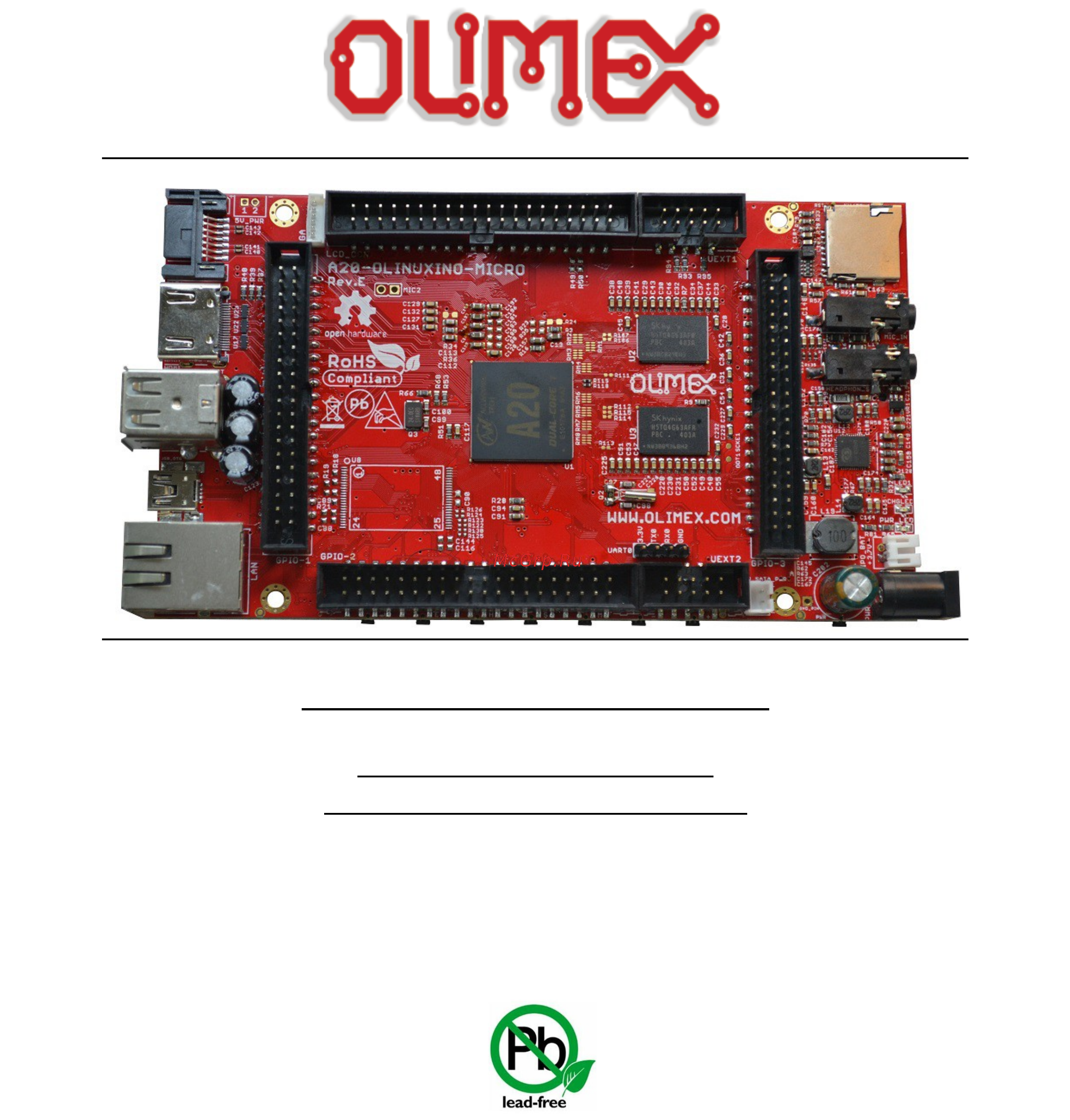
A20-OLinuXino-MICRO
Open-source single-board
Android/Linux mini-computer
USER’S MANUAL
Revision O, March 2015
Designed by OLIMEX Ltd, 2015
All boards produced by Olimex LTD are ROHS compliant
Содержание
- A20 olinuxino micro 1
- Android linux mini computer 1
- Open source single board 1
- User s manual 1
- Disclaimer 2
- There is no warranty for the design materials and the components used to create a20 olinuxino micro they are considered suitable only for a20 olinuxino micro 2
- Chapter 1 overview 5 3
- Chapter 2 setting up the olinuxino board 8 3
- Chapter 3 a20 olinuxino micro board description 19 3
- Chapter 4 the allwinner a20 embedded processor 21 3
- Chapter 5 control circuity 23 3
- Disclaimer 2 3
- Table of contents 3
- Chapter 6 connectors and pinout 24 4
- Chapter 7 schematics 45 4
- Chapter 8 revision history and support 47 4
- Chapter 1 overview 5
- Features 5
- Introduction to the chapter 5
- Board variants 6
- Board version used in the manual 6
- Target market and purpose of the board 6
- Organization 7
- Chapter 2 setting up the olinuxino board 8
- Electrostatic and electrical polarity warning 8
- Introduction to the chapter 8
- Requirements 8
- Powering the board 9
- Button functions 10
- Prebuilt software 10
- Interacting with the board 11
- Hdmi monitor 12
- Ssh via ethernet 12
- Ssh via mini usb cable in debian 12
- Vga monitor 12
- Changing the default image resolution 13
- Lcd display 13
- All lcd displays made by olimex have at least a 0 lcd connector going for an lcd output you would also need need and a cable to attach the display to the board the cable is sold separately 15
- Cable idc40 15cm 15cm long cable suitable for 0 step connectors product page cable 40 40 10cm 10cm long cable suitable for 0 5 step connectors product page 15
- Connecting and calibrating a display 15
- One of the ways to interact with the board is via an external display with or without touchscreen component the 40 pin male connector lcd_con has the typical 0 pin step all olimex displays have corresponding 40 pin male connector you would only need a 0 female female cable for the hardware connection 15
- Reboot 15
- Script fex note that script bin fex contains configuration settings and definitions not only for the video output but also for the pin descriptions and names power setting and much more if you really want to modify and customize the default images to change port functions port names to disable specific peripherals you would need to be able to edit the script files please refer to the following web page for more information http linux sunxi org fex_guide 15
- The cable used for connection depends on the specific board you are using and more specifically it depends on the pitch of the lcd connector of the board we have two cables both 40 pins ones but one for the bigger pitch 0 and the other for the smaller one 0 5 each of the displays listed in the table above has two connectors suitable for both cables 15
- The displays recommended for the board at the moment of writing might be found in the table below 15
- The displays whose names contain ts include a resistive touch screen component 15
- This will convert script fex to script bin and the script bin file will be written to the microsd card 15
- Android calibration 16
- Debian calibration 16
- Gpio under debian 16
- I2c and spi under debian 17
- Software support 17
- Chapter 3 a20 olinuxino micro board description 19
- Introduction to the chapter 19
- Layout top view 19
- At the bottom of the board there are mainly buttons and the large sd mmc connector 20
- Layout bottom view 20
- Chapter 4 the allwinner a20 embedded processor 21
- Introduction to the chapter 21
- The processor 21
- Block diagram 22
- Chapter 5 control circuity 23
- Clocks 23
- Introduction to the chapter 23
- Power supply circuit 23
- Chapter 6 connectors and pinout 24
- Communication with the a20 24
- Introduction to the chapter 24
- Usb otg communication nand firmware repair update 24
- Consider table below when connecting the usb serial cable f according to the wire color code the rx line of the cable green wire should go to tx line of the target board the tx line of the cable red wire should go to the rx line of the target board the blue wire should go to the target s gnd line 26
- Note that by default only uart0 is defined as a port suitable for serial debug you can use our usb serial cable f for debugging uext1 and uext2 are not defined by default 26
- The uart0 might be used for uart communication by default it is typically used for serial terminal debug the uexts are typically used for connecting additional modules 26
- The uext connectors are used as an interface for the olimex s uext modules usually boards with mod prefix in their commercial names for more information on uext please visit https www olimex com products modules uext resources uext pdf 26
- Uart0 uext1 uext2 interface 26
- Sd card connectors 27
- Sd mmc1 slot 28
- Sd mmc1 slot is the smaller microsd card slot located on the top of the board 28
- The schematic related to the sd mmc1 microsd connector is shown below 28
- This slot is typically used for booting the os due to the larger capacities of the microsd cards compared to sd or mmc cards it is suggested to have an sd card with a proper linux android image especially if you have ordered a version of the board without nand memory it is also recommended to use class 10 10mbyte sec card for faster read write operations lower class cards especially higher capacity ones might slow down the whole system 28
- Additionally there are the wp and cp switches that are responsible respectively for sensing whether the card is locked for reading and whether there is a card inserted 29
- Note that by default this connector is not suitable for booting os such support is possible but not implemented in the official software releases 29
- Sd mmc slot 29
- The schematic related to the sd mmc1 sd mmc connector is shown below 29
- The sd mmc2 slot is located on the back of the pcb and works with the larger sd and mmc cards the connector was placed by a popular demand 29
- Mic_in headphones connectors 30
- Pwr jack 30
- The connector can interface standard 3 mm phone connector also known stereo plug or audio plug 31
- The default audio output is set to the hdmi connector for displays and monitors with built in audio speakers if you wish to use audio out you need to first disconnect the hdmi boot the board connect the audio out device speakers and finally connect the hdmi 31
- The part of the schematic related to the usb_otg is shown below 31
- The socket can interface standard 3 mm phone connector also known stereo plug or audio plug 31
- The sy6280 responsible for the usb_otg is enabled by usb0 drv processor pin c12 thus the usb_otg is also controlled by the same signal 31
- The usb_otg features low loss power distribution switch sy6280 which protects the board in case the devices you have plugged to the usb_otg attempt to draw more current than 523ma combined the maximum current available on the 5v usb_otg is exactly 523ma 31
- There are two parts of a successful otg device host mode switch and usage hardware part and 31
- Usb_otg connector 31
- Software part 32
- The connector case is also grounded 32
- The hardware part is the cable to use the otg as a host you would need a mini usb to usb adapter cable do not confuse micro and mini usb to use it as a device simple 32
- The software part is loading a kernel module responsible for the behavior of the board while in device mode if such software is not enabled or missing in the official distribution you would need respectively either to load the module or rebuild the kernel to enable the module there are several modules that you might need depending on what your goals are 32
- Usb_host connector 33
- 10 100mbps operation full half duplex operation supports auto crossover detection adaptive equalization ieee 802 802 u compliant supports ieee 802 u clause 28 1 v operation with 3 v io signal tolerance and much more 34
- Auto eth0 iface eth0 inet dhcp 34
- Auto eth0 iface eth0 inet static address 192 68 netmask 255 55 55 gateway 192 68 54 34
- Etc network interfaces 34
- Ethernet 34
- For dhcp you need to enable auto detection and dhcp as shown below 34
- For setting a static address please follow the pattern below 34
- If you use linux then the ethernet connector might be used for ssh connection to the board if you lack any other option for debugging it might be hard to guess the correct ip of the board since it has dhcp enabled by default especially if you are in a large network it is good idea to check the default settings by exploring the linux image settings those are usually stored in 34
- The eeprom memory may be used to store the mac address 34
- The ethernet connector is grounded according to the standard check gnd1 and gnd2 lines on the schematics 34
- The gnd is common for both levels of the usb_host 34
- The lan connectivity is handled by realtek s rtl8201cp some of the features of this 10 100mbit controller are 34
- Ifconfing a dhclient eth as seen after after the ifconfing command 35
- Important in some debian images it is possible that the ethernet doesn t get auto detected during boot up this is done on purpose because if there is auto detection enabled and you don t want to use the ethernet connector or you have forgotten to plug a cable the start up would be greatly delayed this might be problem in the first start up to users counting only on ssh connection you can enable the ethernet after a successful boot up with 35
- Important you can configure static dhcp given ip addresses in etc network interfaces 35
- Hdmi connector 36
- Note that there are different linux images depending whether the hdmi tv works at 50hz or 60hz refresh rate if you board runs android there is a specific option to set the appropriate hdmi output 36
- Pin 14 of the hdmi is not mandatory in hdmi 1 1 c it is reserved pin in hdmi 1 it is optional 36
- The part of the schematic that describes the hdmi module is shown below 36
- Back view of the 15 pin connector 37
- Please note that you would need a specific android image for the vga output with proper display and output settings we don t provide such image ready at the moment 37
- The vga output has been tested only with the official debian linux image so far and it works fine after selecting the proper mode by executing change_display sh 37
- Vga connector 37
- You would probably need an adapter cable for the vga display 6 pin connector to 15 pin female rgb cable you can make the cable or the connection yourself or you can purchase the olimex made cable https www olimex com products components cables a20 vga cable note that you also have to change the script under debian as explained in chapter 2 calibrating a display 37
- Sata connector and power 38
- The part of the schematic describing the sata module is shown below 38
- Gpio 1 general purpose input output 40pin connector 39
- Gpio ports 39
- Most of the pins are already defined in default operating system images some of them can be used as gpios i2c or spi without much of a problem information on the software usage of gpio ports might be found in chapters 2 gpio under debian and 2 i2c and spi under debian 39
- The gpio 1 plastic connector has 14 pins the signal layout is described below 39
- The yellow part of the table shows all the signals shared with the 6 pin vga connector 39
- There are three gpio ports which are used generally to access unused by the board s peripherals pins however there are exceptions some of the pins might be used to easily peripherals or their levels 39
- Gpio 2 general purpose input output 40pin connector 40
- The gpio pins are led out on a separate 40pin connecter they allow the user to attach additional hardware check readings or perform hardware debug the gpio 2 connector numbers are printed at the bottom of the board for your convenience 40
- Gpio 3 connector features the signals of axp152 on a convenient header the signals available might be used to implement power controls on the board for instance turning off the device at specific voltage level or detecting levels 41
- Gpio 3 general purpose input output 40pin connector 41
- Pb14 ms0 tms gpio 3 26 pb15 ck0 tck gpio 3 28 pb16 do0 tdo gpio 3 30 pb17 di0 tdi gpio 4 32 41
- The jtag signals might also be accessed at this header 41
- The yellow part of the table shows the jtag signals 41
- These signals might be conveniently accessed on gpio 3 connector these jtag signals might be found at processor port pb the pins of the connector are respectively gpio 3 26 gpio 3 28 gpio 3 30 gpio 4 32 more specifically 41
- You would also need vdd and gnd which might be found on various places on the board this information should be sufficient to establish a hardware connection the connection would depend 41
- Important you need additional 40pin ribbon cable to connect an olimex display and the lcd_con 43
- Lcd_con 40pin connector 43
- The lcd connector is suitable for a number of olimex displays and touchscreen panels with different native resolution the smallest available is the 4 one called lcd olinuxino 4 ts 43
- The lcd_con pins are led out on a separate 40pin connecter for the ease of connecting an lcd we have tested the ability of the board to interact with such a display they allow the user to attach additional hardware check readings or perform hardware debug 43
- Important 44
- Jumper description 44
- Please note that most the jumpers on the board are smt type if you feel insecure of your soldering cutting technique it is better not to try to adjust the jumpers since it is possible to damage the board 44
- To use android with display or resolution different than hdmi and 1024 600 default settings you need to upload new android image to the board these images are available here https www olimex com wiki a20 olinuxino micro using an operating system nand flash in debian linux you would need to start a start a shell script to change the built in the image resolution settings start it with change_display_a20_olinuxino sh and follow the instructions please refer to chapter 2 changing the default image resolution for more details 44
- With native screen resolution of 480 272 through the 7 one named lcd olinuxino 7ts with 800 480 to the 1024 600 10 lcd olinuxino 10ts 44
- Additional hardware components 45
- Chapter 7 schematics 46
- Eagle schematic 46
- Introduction to the chapter 46
- Physical dimensions 47
- Chapter 8 revision history and support 48
- Document revision 48
- In this chapter you will find the current and the previous version of the document you are reading also the web page for your device is listed be sure to check it after a purchase for the latest available updates and examples 48
- Introduction to the chapter 48
- Board revision 50
- Remember to check the schematics and the board design files to compare the differences 50
- Useful web links and purchase codes 51
- Frequently asked questions 52
- For product support hardware information and error reports mail to support olimex com all document or hardware feedback is welcome note that we are primarily a hardware company and our software support is limited please consider reading the paragraph below about the warranty of olimex products 55
- Olimex 2015 a20 olinuxino micro user s manual 55
- Page 55 of 55 55
- Product support 55
- The full text might be found at https www olimex com wiki gtc warranty for future reference 55
Похожие устройства
- OLIMEX A20-SOM Инструкция по эксплуатации
- OLIMEX A20-SOM204-1G Инструкция по эксплуатации
- OLIMEX A20-SOM204-1G-M Инструкция по эксплуатации
- OLIMEX A20-204-1G16M16GMC Инструкция по эксплуатации
- OLIMEX A20-SOM-E16GS16M Инструкция по эксплуатации
- OLIMEX A20-SOM-EVB Инструкция по эксплуатации
- OLIMEX A20-SOM-EVB-8GB Инструкция по эксплуатации
- OLIMEX A20-SOM-N8GB Инструкция по эксплуатации
- OLIMEX A33-OLINUXINO Инструкция по эксплуатации
- OLIMEX A33-OLINUXINO-4GB Инструкция по эксплуатации
- OLIMEX A33-OLINUXINO-N8G Инструкция по эксплуатации
- OLIMEX A64-1G Инструкция по эксплуатации
- OLIMEX A64-1GE16GW Инструкция по эксплуатации
- OLIMEX A64-1G4GW Инструкция по эксплуатации
- OLIMEX A64-1GS16M Инструкция по эксплуатации
- OLIMEX A64-2GE8G-IND Инструкция по эксплуатации
- OLIMEX AM3352-SOM Инструкция по эксплуатации
- OLIMEX AM3352-SOM512MIND Инструкция по эксплуатации
- OLIMEX AM3352-SOMEVBIND Инструкция по эксплуатации
- OLIMEX AM3352-SOM-IND Инструкция по эксплуатации