
Icom AT-180 Инструкция по эксплуатации онлайн
Содержание
Похожие устройства
- Ardo TLN 106 SA Инструкция по эксплуатации
- Icom BC-137 Инструкция по эксплуатации
- PocketBook 360 Plus Grey Инструкция по эксплуатации
- Ardo TLN 106 EW Инструкция по эксплуатации
- PocketBook Pro 622 Black Инструкция по эксплуатации
- Icom BC-143 Инструкция по эксплуатации
- Ardo TLN 125 LW Инструкция по эксплуатации
- Wexler Book T7004 White+чехол Инструкция по эксплуатации
- Icom IC-B144 Инструкция по эксплуатации
- Ardo TLN 105 LW Инструкция по эксплуатации
- Icom BC-146 Инструкция по эксплуатации
- Apple MacBookPro MC975RS/A Инструкция по эксплуатации
- Ardo TLN 105 SW Инструкция по эксплуатации
- Apple MacBookPro MC976RS/A Инструкция по эксплуатации
- Icom HM-127 Инструкция по эксплуатации
- Ardo TLN 85 SW Инструкция по эксплуатации
- Icom IC-PW1 Инструкция по эксплуатации
- Ardo TLN 85 EW Инструкция по эксплуатации
- Icom PS-125 Инструкция по эксплуатации
- Ardo TLN 65 EW Инструкция по эксплуатации
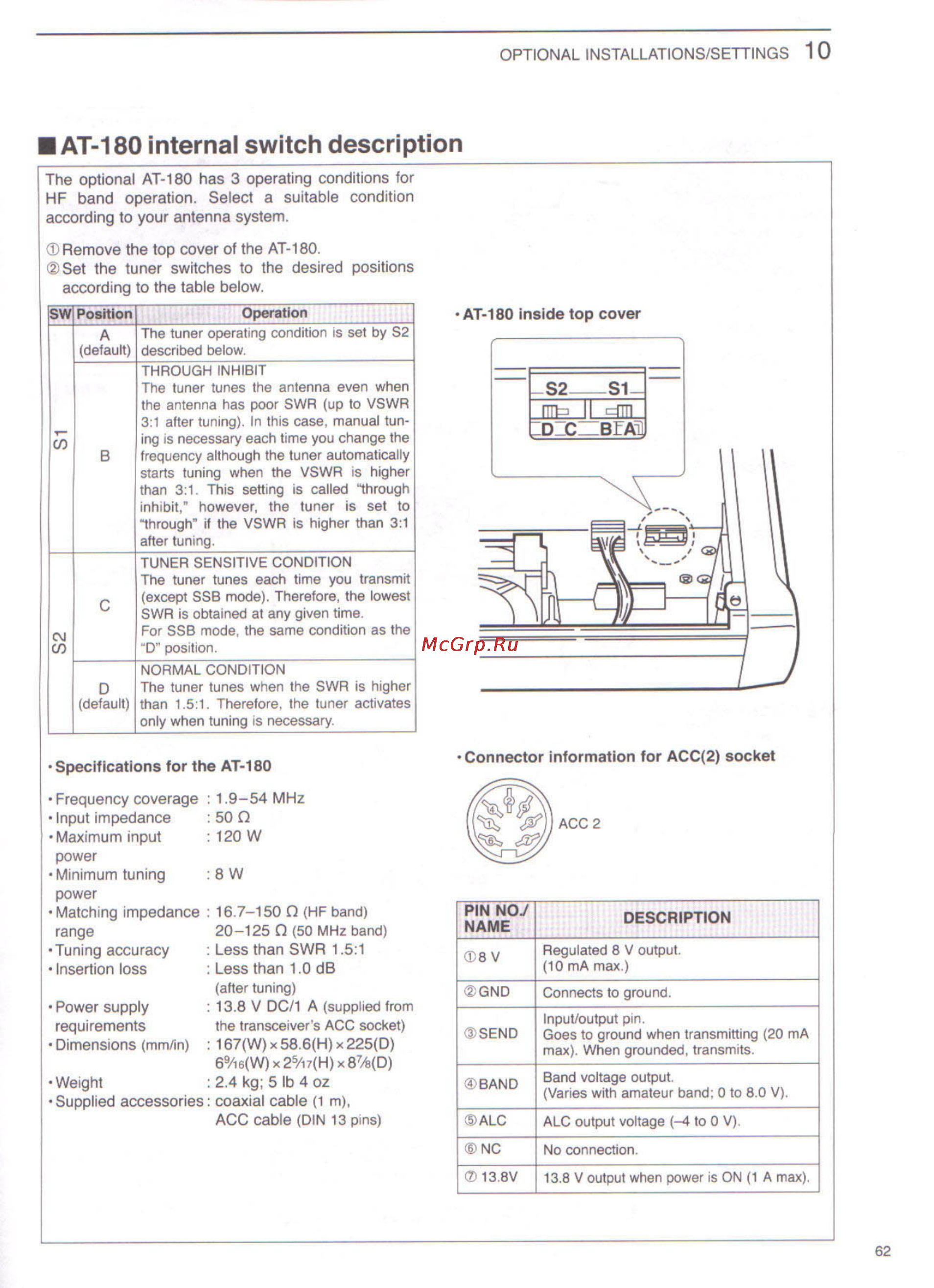
OPTIONAL INSTALLATIONS SETTINGS 10 AT 180 internal switch description The optional AT 180 has 3 operating conditions for HF band operation Select a suitable condition according to your antenna system Remove the top cover of the AT 180 Set the tuner switches to the desired positions according to the table below ____________ Operation____________ The tuner operating condition is set by S2 A default described below THROUGH INHIBIT The tuner tunes the antenna even when the antenna has poor SWR up to VSWR 3 1 after tuning In this case manual tun ing is necessary each time you change the frequency although the tuner automatically starts tuning when the VSWR is higher than 3 1 This setting is called through inhibit however the tuner is set to through if the VSWR is higher than 3 1 after tuning CM œ TUNER SENSITIVE CONDITION The tuner tunes each time you transmit r except SSB mode Therefore the lowest SWR is obtained at any given time For SSB mode the same condition as the D position NORMAL CONDITION D The tuner tunes when the SWR is higher default than 1 5 1 Therefore the tuner activates only when tuning is necessary Specifications for the AT 180 Frequency coverage Input impedance Maximum input power Minimum tuning power Matching impedance range Tuning accuracy Insertion loss Connector information for ACC 2 socket 1 9 54 MHz 50 Q 120 W 8W 16 7 150 Q HF band 20 125 Q 50 MHz band PIN NO NAME Less than SWR 1 5 1 Less than 1 0 dB 8V Regulated 8 V output 10 mA max after tuning GND Connects to ground SEND Input output pm Goes to ground when transmitting 20 mA max When grounded transmits BAND Band voltage output Varies with amateur band 0 to 8 0 V ALC ALC output voltage 4 to 0 V NC No connection 13 8V 13 8 V output when power is ON 1 A max Power supply 13 8 V DC 1 A supplied from the transceiver s ACC socket requirements Dimensions mm in 167 W x 58 6 H x 225 D 69 i6 W x25 i7 H x 87a D Weight 2 4 kg 5 lb 4 oz Supplied accessories coaxial cable 1 m ACC cable DIN 13 pins DESCRIPTION 62