
Daikin EHVH04S18CB3VF Схема онлайн
Addendum to the documentation set
1
*4P412945-1 0000000N*
EHVH04CB3VF
Addendum to the documentation set
EHVH08CB3VF
We advise to first carefully read this addendum and only then to consult delivered manuals and proceed with installation of the unit.
For this floor standing low temperature heat pump EHVH04CB3VF or EHVH08CB3VF, instructions in the manuals delivered with the unit are these
of the EHVH04CB3V or EHVH08CB3V.
All delivered manuals as well as the Installer reference guide and User reference guide referred to in delivered manuals apply, but there are some
exceptions and attention points for the “F”-version units.
These exceptions and attention points are described in this addendum.
Differences mainly relate to
1) water piping and refrigerant piping connections (see pictures in this addendum);
2) the built-in 12 l flow-through vessel under the domestic hot water tank (which impacts on the minimum water volume of the installation);
3) lay-out of the internal piping;
4) impact of these differences on technical specification drawings. The correct versions are therefore added to this addendum.
There is no difference for everything related to the user interface, the software or the operation of the unit. All information in the delivered manual
related hereto is therefore correct.
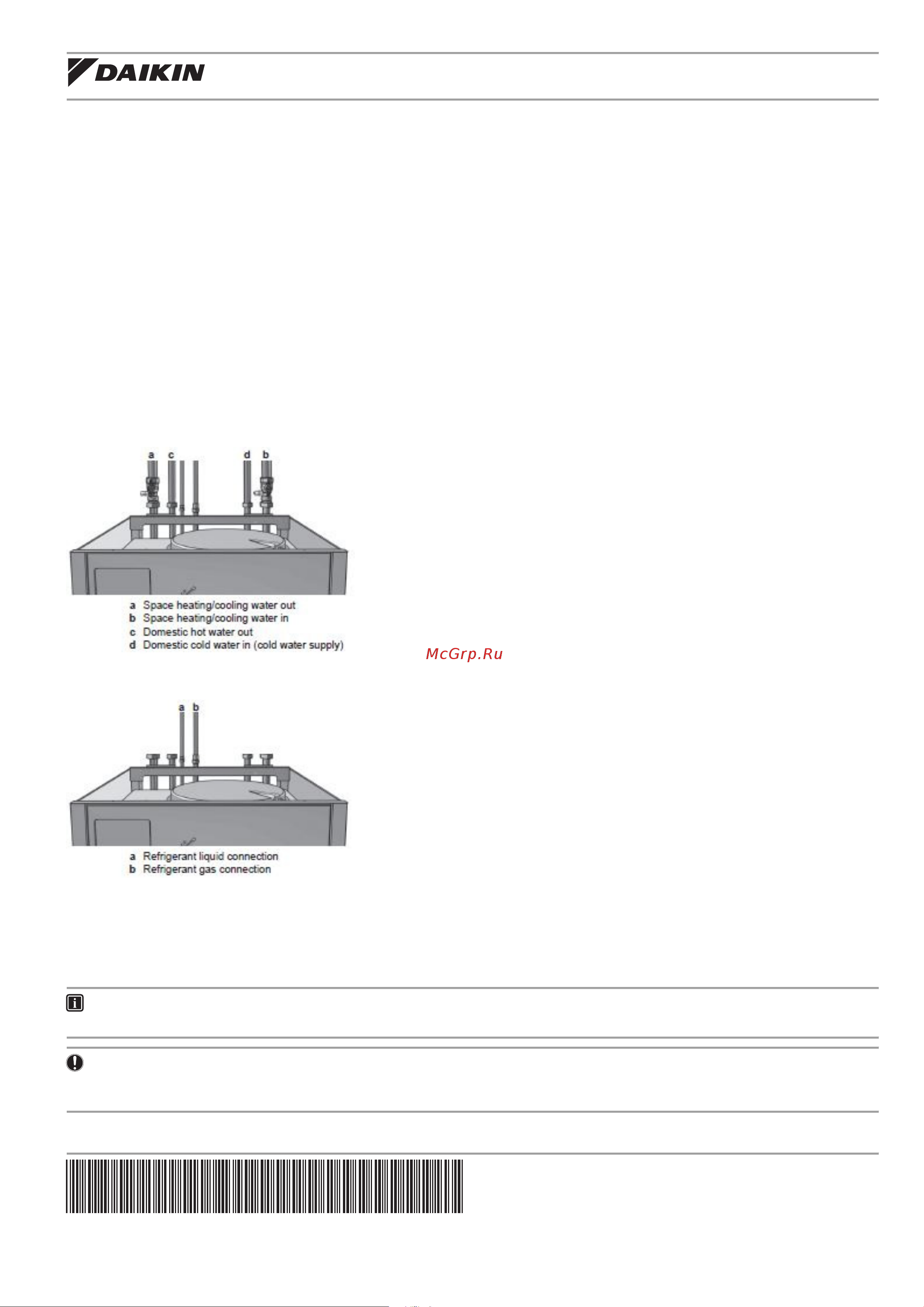
1. Water piping connections and refrigerant piping connections
The following picture illustrates the water piping connections of your unit (chapter “To connect the water piping”). Analogous pictures in the
EHVH04/08CB3V manual are to be neglected.
The following picture illustrates the refrigerant piping connections of your unit (chapter “To connect the refrigerant piping to the indoor unit”).
Analogous pictures in the EHVH04/08CB3V manual are to be neglected as well.
2. Minimum water volume (chapter “To check the water volume and flow rate)
ONLY applicable for EHVH04+08S18CB3VF
The system does not require a minimum water volume. Since an extra flow-through vessel is built into the unit, the total water volume in the
installation can be 0 l. It is however required that when all heat emitters are closed, the user interface displays a minimum water flow of 15 l/min.
INFORMATION
Critical processes or rooms with a high heat load may require extra water.
NOTICE
When circulation in each space heating loop is controlled by remote controlled valves, it is important that a minimum water flow of 15 l/min is
guaranteed, even if all valves are closed.
Содержание
- Addendum to the documentation set 1
- A a flow sensor b backup heater 4 impact of these differences on technical specification drawings chapter technical data of the installer reference guide referred to in delivered manuals piping diagram indoor unit 2
- Addendum to the documentation set 4p412945 1 2015 6 2
- D077572 1a page 2 2
- Lay out of internal piping 2
- Allows isolation of the indoor unit water circuit side from the residential water circuit side 3
- Allows readout of the water pressure in the water circuit 3
- C d e f 3
- Circulates the water in the water circuit 3
- Components indoor unit 3
- Contains the main electronic and electrical parts of the indoor unit 3
- Controls whether the water is used for space heating or the domestic hot water tank 3
- Determines the water and refrigerant temperature at various points in the circuit 3
- Empties the full tank 3
- Gives feedback to the interface about the actual flow based on this information and other the interface adjusts the pump speed 3
- P412945 1 2015 6 addendum to the documentation set 3
- Prevents excessive water pressure in the water circuit by opening at 3 bar 3
- Provides additional heating in case of cold outdoor temperatures also serves as backup in case of malfunctioning of the outdoor unit 3
- Remaining air in the water circuit will be automatically removed via the air purge valve 3
- Removes dirt from the water to prevent damage to the pump or blockage of the heat exchanger 3
- The protector activates when the temperature of the backup heater becomes too high 3
- Addendum to the documentation set 4p412945 1 2015 6 4
- D087616 1 4
- Dimensions and service space indoor unit dimensions pay special attention towards position of water piping connections and of refrigerant piping connections 4
- G h i d j g 4
- L b a k 4
- Note 1 typical field installation is according to local and national regulations 4
- Service space service space service space of ehvh04cb3v f or ehvh08cb3v f units is same as service space of ehvh04cb3v and ehvh08cb3v units and therefore not considered in this addendum 4
Похожие устройства
- Daikin EHVH08S18CB3VF Инструкция по эксплуатации
- Daikin EHVH08S18CB3VF Схема
- Daikin EKMBUHBA6V3 Инструкция по эксплуатации
- Daikin EBHQ006BBV3 Инструкция по эксплуатации
- Daikin EBHQ006BBV3 Приложение к руководству для дополнительного оборудования
- Daikin EBHQ006BBV3 Инструкция по монтажу
- Daikin EBHQ008BBV3 Инструкция по эксплуатации
- Daikin EBHQ008BBV3 Приложение к руководству для дополнительного оборудования
- Daikin EBHQ008BBV3 Инструкция по монтажу
- Foodatlas Постмикс LEF-4\5 Foodatlas Eco Инструкция по эксплуатации
- Foodatlas Постмикс LEF-4\5 Foodatlas Eco Сертификат
- Foodatlas Постмикс LEF-3\5 Foodatlas Eco Инструкция по эксплуатации
- Foodatlas Постмикс LEF-3\5 Foodatlas Eco Сертификат
- Foodatlas H001 Инструкция по эксплуатации
- Foodatlas H001 Сертификат
- Foodatlas PS-1 Инструкция по эксплуатации
- Foodatlas PS-1 Сертификат
- Foodatlas SM-1388 Инструкция по эксплуатации
- Foodatlas SM-1388 Сертификат
- Daikin EBLQ05C2V3 Руководство по монтажу