![Makita HM0871C [17/17] P 17 17](/img/pdf.png)
Makita HM0871C [17/17] P 17 17
![Makita HM0871C [17/17] P 17 17](/views2/1844696/page17/bg11.png)
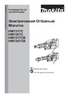
Wiring diagram
P 17/ 17
Fig. D-3
Handle
Lead Unit
Fig. D-4
Polyethylene Tube Ø8-30
Connector
for connecting to Switch
for connecting to Terminal block
Pass the Lead wires of Lead unit through Polyethylene tube illustrated below.
Lead unit’s Lead wires
Lead unit’s Lead wires have to
be put on both side of Boss,
And connect them to Switch
and Terminal.
Lead unit’s Lead wires bundled
with Polyethylene tube has to put
under Terminal block.
Boss
Terminal block
Sponge sheet
Connector of
Lead unit
Put the following Lead wires
of Lead unit into Sponge sheet.
* Lead wire (black) for connecting to Switch
* Lead wire (black) for connecting to Terminal
block
* Lead wire (white) for connecting to Switch
The Lead wires have
to be tightened in this
area.
Polyethylene
tube
Содержание
- Echnical information p.1
- Necessary repairing tools p.2
- Lubrications p.2
- Caution repair the machine in accordance with instruction manual or safety instructions p.2
- P 2 17 p.2
- P 3 17 p.3
- Epair 3 disassembly assembly 3 1 chuck section p.3
- P 4 17 p.4
- Disassembly assembly 3 2 tool holder section p.4
- P 5 17 p.5
- Disassembly assembly 3 2 tool holder section cont p.5
- 3 active dynamic vibration absorber exclusively for hm0871c p.5
- P 6 17 p.6
- Disassembly assembly 3 3 active dynamic vibration absorber exclusively for hm0871c cont p.6
- P 7 17 p.7
- Disassembly assembly 3 4 piston striker cylinder p.7
- P 8 17 p.8
- Disassembly assembly 3 4 piston striker cylinder cont p.8
- P 9 17 p.9
- Disassembly assembly 3 5 crank shaft p.9
- P 10 17 p.10
- Disassembly assembly 3 5 crank shaft p.10
- P 11 17 p.11
- Disassembly assembly 3 5 crank shaft cont p.11
- 6 cylinder section p.11
- P 12 17 p.12
- Disassembly assembly 3 7 controller p.12
- 8 armature p.12
- P 13 17 p.13
- Disassembly assembly 3 8 armature cont p.13
- P 14 17 p.14
- 9 handle section p.14
- P 15 17 p.15
- Maintenance program p.15
- Disassembly assembly 3 10 fastening torque p.15
- Ircuit diagram p.16
- P 16 17 p.16
- Note in wiring p.16
- Iring diagram p.16
- P 17 17 p.17
- Lead unit p.17
- Iring diagram p.17
- Handle p.17
Похожие устройства
-
 Makita HM1307CBРуководства пользователя
 -
Makita HM1317CРуководства пользователя
-
Makita HM1307CРуководства пользователя
-
Makita HM1317CBРуководство пользователя
-
 Makita HM1214CРуководства пользователя
 -
 Makita HM002GZ03Инструкция
 -
 Makita HM002GZ03Деталировка
 -
 Makita HM001GZ02Инструкция
 -
 Makita HM001GZ02Деталировка
 -
 Makita HM0871CТехническое описание
 -
 Makita HM0871CИнструкция по эксплуатации
 -
 Makita HK1820Техническое описание