![Makita HM0871C — инструкция по разборке и сборке цилиндра и его компонентов [8/17]](/img/pdf.png)
Makita HM0871C — инструкция по разборке и сборке цилиндра и его компонентов [8/17]
![Makita HM0871C [8/17] P 8 17](/views2/1844696/page8/bg8.png)
P 8/ 17
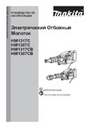
Fig. 17
Fig. 18
DISASSEMBLING
[3] DISASSEMBLY/ASSEMBLY
[3]-4 Piston, Striker, Cylinder (cont.)
Remove Cylinder section by tapping Barrel using
plastic hammer. Pay attention to the tapped position.
Ring 20, Rubber ring 20, Flat washer 23, Guide ring,
Slide sleeve are removed from Cylinder section.
(4) Separate Cylinder section from Barrel. The parts on Tool holder side can be removed from Cylinder 32 as per the right
illustration in Fig. 17.
(5) Pressing down Ring 36, remove Ring spring 34 (A) from Groove (A) on Cylinder 32 with 1R291.
The components of Cylinder section can be separated by removing Ring spring 34 (B) and (C). (Fig. 18.)
Barrel
Barrel
Ring 20
fit to the long drum side
of Impact bolt
Guide ring
Slide sleeve
Cylinder 32
Rubber ring 20
Flat washer 23
Cylinder Section
Ring 36
Groove (A)
on Cylinder 32
Ring spring 34
1R291
Compression
spring 37
Cylinder guide
Repair
Cylinder 32
Ring spring 34 (A)
groove(A)
groove(B)
groove(C)
Ring spring 34 (B)
Ring spring 34 (C)
Ring 36
Compression
spring 37
Cylinder guide
O ring 46
Ring washer 34
(See Fig. 15.)
Содержание
- Echnical information p.1
- Necessary repairing tools p.2
- Lubrications p.2
- Caution repair the machine in accordance with instruction manual or safety instructions p.2
- P 2 17 p.2
- P 3 17 p.3
- Epair 3 disassembly assembly 3 1 chuck section p.3
- P 4 17 p.4
- Disassembly assembly 3 2 tool holder section p.4
- P 5 17 p.5
- Disassembly assembly 3 2 tool holder section cont p.5
- 3 active dynamic vibration absorber exclusively for hm0871c p.5
- P 6 17 p.6
- Disassembly assembly 3 3 active dynamic vibration absorber exclusively for hm0871c cont p.6
- P 7 17 p.7
- Disassembly assembly 3 4 piston striker cylinder p.7
- P 8 17 p.8
- Disassembly assembly 3 4 piston striker cylinder cont p.8
- P 9 17 p.9
- Disassembly assembly 3 5 crank shaft p.9
- P 10 17 p.10
- Disassembly assembly 3 5 crank shaft p.10
- P 11 17 p.11
- Disassembly assembly 3 5 crank shaft cont p.11
- 6 cylinder section p.11
- P 12 17 p.12
- Disassembly assembly 3 7 controller p.12
- 8 armature p.12
- P 13 17 p.13
- Disassembly assembly 3 8 armature cont p.13
- P 14 17 p.14
- 9 handle section p.14
- P 15 17 p.15
- Maintenance program p.15
- Disassembly assembly 3 10 fastening torque p.15
- Ircuit diagram p.16
- P 16 17 p.16
- Note in wiring p.16
- Iring diagram p.16
- P 17 17 p.17
- Lead unit p.17
- Iring diagram p.17
- Handle p.17
Похожие устройства
-
 Makita HM1307CBРуководства пользователя
 -
Makita HM1317CРуководства пользователя
-
Makita HM1307CРуководства пользователя
-
Makita HM1317CBРуководство пользователя
-
 Makita HM1214CРуководства пользователя
 -
 Makita HM002GZ03Инструкция
 -
 Makita HM002GZ03Деталировка
 -
 Makita HM001GZ02Инструкция
 -
 Makita HM001GZ02Деталировка
 -
 Makita HM0871CТехническое описание
 -
 Makita HM0871CИнструкция по эксплуатации
 -
 Makita HK1820Техническое описание
Подробное руководство по разборке и сборке цилиндра, включая удаление и замену ключевых компонентов. Узнайте, как правильно обращаться с деталями для эффективного ремонта.