![AMERICAN DJ Stinger Star [5/14] Special note line termination](/img/pdf.png)
AMERICAN DJ Stinger Star [5/14] Special note line termination
![AMERICAN DJ Stinger Star [5/14] Special note line termination](/views2/2012546/page5/bg5.png)
ADJ Products, LLC - www.adj.com - Stinger Star Instruction Manual Page 9ADJ Products, LLC - www.adj.com - Stinger Star Instruction Manual Page 8
5-Pin XLR DMX Connectors.
Some manufactures use 5-pin XLR
connectors for DATA transmission in place of 3-pin. 5-pin XLR xtures
may be implemented in a 3-pin XLR DMX line. When inserting stan-
dard 5-pin XLR connectors in to a 3-pin line a cable adaptor must be
used, these adaptors are readily available at most electric stores. The
chart below details a proper cable conversion.
Conductor 5-Pin XLR Male (In)3-Pin XLR Female (Out)
Pin 1
Pin 5 - Do Not Use
Pin 4 - Do Not Use
Pin 3
Pin 2
Pin 1
Pin 3
Pin 2
Not Used
Not Used
Data True (+ signal)
Data Compliment (- signal)
Ground/Shield
3-Pin XLR to 5-Pin XLR Conversion
Stinger Star DMX Set Up
The unit should be mounted using a mounting clamp (not provided),
axing it to the mounting bracket that is provided with the unit.
Always ensure that the unit is rmly xed to avoid vibration and slip-
ping while operating. Always ensure that the structure to which you
are attaching the unit is secure and is able to support a weight of 10
times the unit’s weight. Also, always use a safety cable that can hold
12 times the weight of the unit when installing the xture.
The equipment must be installed by a professional, and it must be
installed in a place where it is out of the reach of people’s grasp.
Stinger Star Installation
Stinger Star DMX Set Up
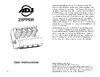
Notice: Be sure to follow gures two and three when making your own
cables. Do not use the ground lug on the XLR connector. Do not con-
nect the cable’s shield conductor to the ground lug or allow the shield
conductor to come in contact with the XLR’s outer casing. Grounding
the shield could cause a short circuit and erratic behavior.
DMX512 IN
3-PIN XLR
SOUND
REMOTE
CONTROL
INPUT
POWER
INPUT OUTPUT
SOUND
REMOTE
CONTROL
INPUT
POWER
INPUT OUTPUT
SOUND
REMOTE
CONTROL
INPUT
POWER
INPUT OUTPUT
DMX512
DMX+,DMX-,COMMON
1
2
3
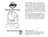
Termination reduces signal errors and
avoids signal transmission problems
and interference. It is always advisable
to connect a DMX terminal, (Resistance
120 Ohm 1/4 W) between PIN 2 (DMX-)
and PIN 3 (DMX +) of the last fixture.
1
2
3
1
2
3
DMX +
DMX -
COMMON
DMX512 OT
3-PIN XLR
Figure 2
Figure 3
1 Ground
1 Ground
XLR Male Socket
XLR Pin Conguration
3 Hot
2 Cold
2 Cold
3 Hot
XLR Female Socket
Pin 3 = Data True (positive)
Pin 2 = Data Compliment (negative)
Pin 1 = Ground
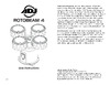
Special Note: Line Termination.
When longer runs of cable are
used, you may need to use a terminator on the last unit to avoid erratic
behavior. A terminator is a 110-120 ohm 1/4 watt resistor which is con-
nected between pins 2 and 3 of a male XLR connector (DATA + and
DATA -). This unit is inserted in the female XLR connector of the last
unit in your daisy chain to terminate the line. Using a cable terminator
(ADJ part number Z-DMX/T) will decrease the possibilities of erratic
behavior.
DMX512 IN
3-PIN XLR
SOUND
REMOTE
CONTROL
INPUT
POWER
INPUT OUTPUT
SOUND
REMOTE
CONTROL
INPUT
POWER
INPUT OUTPUT
SOUND
REMOTE
CONTROL
INPUT
POWER
INPUT OUTPUT
DMX512
DMX+,DMX-,COMMON
1
2
3
Termination reduces signal errors and
avoids signal transmission problems
and interference. It is always advisable
to connect a DMX terminal, (Resistance
120 Ohm 1/4 W) between PIN 2 (DMX-)
and PIN 3 (DMX +) of the last fixture.
1
2
3
1
2
3
DMX +
DMX -
COMMON
DMX512 OT
3-PIN XLR
Figure 4
Содержание
- User instructions p.1
- Stinger star p.1
- Warning p.2
- Unpacking p.2
- Introduction p.2
- Customer support p.2
- Caution p.2
- Stop and read all laser safety data operation instructions and laser safety p.3
- Power supply p.4
- Dmx 512 p.4
- Data compliment signal p.5
- Conductor 5 pin xlr male in 3 pin xlr female out p.5
- When longer runs of cable are used you may need to use a terminator on the last unit to avoid erratic behavior a terminator is a 110 120 ohm 1 4 watt resistor which is con nected between pins 2 and 3 of a male xlr connector data and data this unit is inserted in the female xlr connector of the last unit in your daisy chain to terminate the line using a cable terminator adj part number z dmx t will decrease the possibilities of erratic behavior p.5
- Be sure to follow figures two and three when making your own cables do not use the ground lug on the xlr connector do not con nect the cable s shield conductor to the ground lug or allow the shield conductor to come in contact with the xlr s outer casing grounding the shield could cause a short circuit and erratic behavior p.5
- The unit should be mounted using a mounting clamp not provided affixing it to the mounting bracket that is provided with the unit always ensure that the unit is firmly fixed to avoid vibration and slip ping while operating always ensure that the structure to which you are attaching the unit is secure and is able to support a weight of 10 times the unit s weight also always use a safety cable that can hold 12 times the weight of the unit when installing the fixture the equipment must be installed by a professional and it must be installed in a place where it is out of the reach of people s grasp p.5
- Stinger star installation p.5
- Stinger star dmx set up p.5
- Special note line termination p.5
- Some manufactures use 5 pin xlr connectors for data transmission in place of 3 pin 5 pin xlr fixtures may be implemented in a 3 pin xlr dmx line when inserting stan dard 5 pin xlr connectors in to a 3 pin line a cable adaptor must be used these adaptors are readily available at most electric stores the chart below details a proper cable conversion p.5
- Pin xlr to 5 pin xlr conversion p.5
- Pin xlr dmx connectors p.5
- Pin 5 do not use p.5
- Pin 4 do not use p.5
- Notice p.5
- Not used p.5
- Ground shield p.5
- Data true signal p.5
- Stinger star cad drawing p.6
- Europe version p.6
- Us version p.6
- Stinger star rear layout p.6
- Stinger star laser warning labels p.6
- This will let select your desired dmx channel mode p.7
- System menu when making adjustments press enter to confirm your setup then press and hold the menu button for at least 3 seconds to exit without making any adjust ments press the menu button the display will lock after 30 seconds press the menu button for 3 seconds to unlock p.7
- Show modes 0 6 factory programs p.7
- Show mode speed p.7
- Dmx address setting p.7
- With this function you can have the led display turn off after 10 seconds p.8
- This will let you set unit as a master or slave in a master slave configuration p.8
- This will activate strobing p.8
- This mode can be used as a precaution mode that in case the dmx signal is lost interrupted or power is lost the operating mode chosen in the setup is the running mode the fixture will go into when the dmx signal is lost you can also set this as the operating mode you would like the unit to return to when power is applied p.8
- Sound active mode p.8
- In this mode you can adjust the sound sensitiv ity p.8
- Show mode p.9
- Press the menu button until rset is displayed press the enter button and the unit will reset itself p.9
- With this function you can display the running time of the unit p.9
- Use this function to display the software version of the unit p.9
- Universal dmx control p.9
- This function will run a self test program p.9
- This function will reverse the display 180º p.9
- This function will reset the unit p.9
- The display will show the software version p.9
- Sound active mode p.9
- Uc ir airstream control p.10
- Master slave set up p.10
- Master slave operation p.10
- Laser horizontal position 0 127 select horizontal position 128 255 horizontal move slow fast 12 laser vertical position 0 127 select vertical position 128 255 vertical move slow fast 13 laser path 0 255 select laser path 14 laser path speed 0 255 path speed slow fast p.12
- Fixture cleaning p.12
- Channel value function p.12
- Stinger star notes p.13
- Adj products llc www adj com stinger star instruction manual page 24 adj products llc www adj com stinger star instruction manual page 25 p.13
- Stinger star warranty p.13
- Specifications and improvements in the design of this unit and this manual are subject to change without any prior written notice p.14
- Please note p.14
- Model stinger star p.14
- Auto sensing voltage this fixture contains a automatic voltage switch which will auto sense the voltage when it is plugged into the power source p.14
- Adj products llc 6122 s eastern ave los angeles ca 90040 usa tel 323 582 2650 fax 323 725 6100 web www adj com e mail info americandj com p.14
- A d j supply europe b v junostraat 2 6468 ew kerkrade the netherlands service adjgroup eu www adj com tel 31 45 546 85 00 fax 31 45 546 85 99 p.14
Похожие устройства
-
 AMERICAN DJ Dotz TPAR SystemРуководство по эксплуатации
 -
 AMERICAN DJ Stinger GoboРуководство по эксплуатации
 -
 AMERICAN DJ ZipperРуководство по эксплуатации
 -
 AMERICAN DJ Rotobeam 4Руководство по эксплуатации
 -
 AMERICAN DJ BOOM BOX FX3Руководство по эксплуатации
 -
 ADJ Hydro Beam X1Руководство по эксплуатации
 -
 Involight LDF100Руководство по эксплуатации
 -
 AMERICAN DJ Focus Spot ONEРуководство по эксплуатации
 -
 Involight LED PAR984WРуководство по эксплуатации
 -
 Antari M-7Руководство по эксплуатации
 -
 STAGG SLI KINGPAR22Руководство по эксплуатации
 -
 ADJ Par Z MoveРуководство по эксплуатации