
Scythe Ninja PLUS Rev. B Инструкция по эксплуатации онлайн
Содержание
- 7 isä cpu0a7äß lz ttÿ 1
- I kff 4 w 1
- Installation guide 1
- L 4 5 fs m èdff t è l o 1
- L iifs l l 9 flt è l o 1
- Socket 754 939 940 am2 1
- V f k f1zixyfflt ccpu0 1
- Yyb04o lâzætèl o b nß il 1
- 7m4ffi 2
- Cooler fan 2
- Cpu 37g i ît c4i àj ôl te tirt l o 2
- J 5iclga 775 j1wéâî7 7 wi ytt l âffl y4 lz c sl ctè 2
- Lga 775 2
- Sca cv r ksigoi iîl i fo as i tÿlx 2
- St 5s è tlc wyi s effl ct l 2
- V f kcæufti fccpurozitaia io j x jt îs l 8ottîv 2
- Vftsi kffil iil j 7 xoä ys liia r tèl o 2
- Yj r rzj stèt 2
Похожие устройства
- Sony VAIO VPCF13Z0E Инструкция по эксплуатации
- Pioneer PDP-436 SXE Инструкция по эксплуатации
- Sony VAIO VPCF13S8E Инструкция по эксплуатации
- Scythe Kama Angle Rev. B Инструкция по эксплуатации
- Denon DVD-1720 S Инструкция по эксплуатации
- Sony VAIO VPCF23K1E Инструкция по эксплуатации
- Scythe Ninja 2 Инструкция по эксплуатации
- Denon AVR-1906 S Инструкция по эксплуатации
- Sony VAIO VPCF23C5E Инструкция по эксплуатации
- Scythe Ninja Mini Инструкция по эксплуатации
- Astell&Kern AK100 II 64GB Smoky Blue Инструкция по эксплуатации
- Sony VAIO VPCF23B9E Инструкция по эксплуатации
- Scythe Andy Samurai Master Инструкция по эксплуатации
- Astell&Kern AK120 128GB Titan Инструкция по эксплуатации
- Sony VAIO VPCF23A9E Инструкция по эксплуатации
- Scythe Kama Angle Инструкция по эксплуатации
- Astell&Kern AK120 II 128GB Stone Silver Инструкция по эксплуатации
- Scythe Shuriken Инструкция по эксплуатации
- Sony VAIO VPCF22S8E Инструкция по эксплуатации
- Astell&Kern AK240 256GB Gunmetal Инструкция по эксплуатации
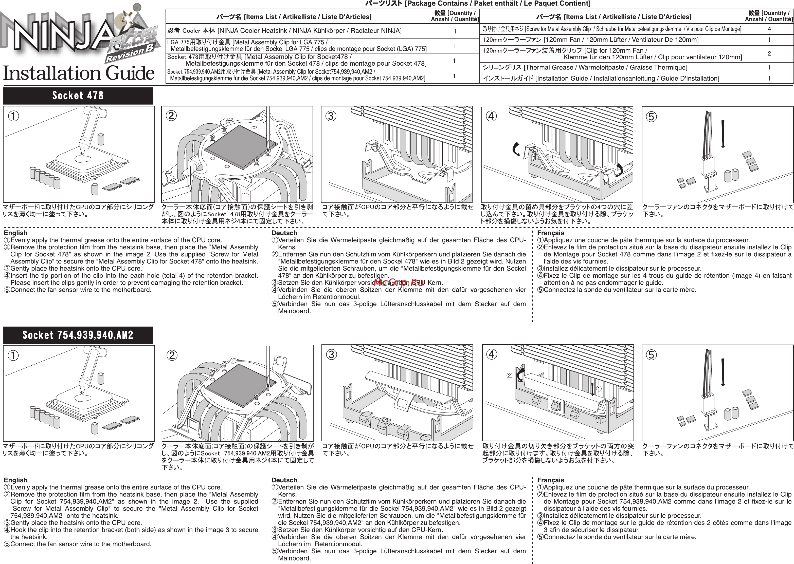
A UXb Package Contains Paket enthält Le Paquet Contient Items List Artikelliste Liste D Articles Cooler Installation Guide NINJA Cooler Heatsink NINJA Kühlkörper Radiateur NINJA Quantity Anzahl Quantité 1 LGA 775ffl VMlt Metal Assembly Clip for LGA 775 1 Metallbefestigungsklemme für den Sockel LGA 775 clips de montage pour Socket LGA 775 Socket 478ffi kJFt Metal Assembly Clip for Socket478 1 Metallbefestigungsklemme für den Sockel 478 clips de montage pour Socket 478 Socket 754 939 940 AM2Wm Metal Assembly Clip for Socket754 939 940 AM2 1 Metallbefestigungsklemme für die Sockel 754 939 940 AM2 clips de montage pour Socket 754 939 940 AM2 V f K F1zI xyFflt cCPU0 A 00 91 Socket T 7 iSÄ CPU0a7äß lz tTÿ Items List Artikelliste Liste D Articles Sts Quantity Anzahl Quantité 4 Montage Screw for Métal Assembly Clip Schraube für MétalIbefestigungsklemme Vis pour Clip de 5F J 120mm 7 j yyy 120mm Fan 120mm Lüfter Ventilateur De 120mm 120mm Clip for 120mm Fan Klemmefürden 120mm Lüfter Clip pour ventilateur 120mm Thermal Grease Wârmeleitpaste Graisse Thermique OXf JL TF Installation Guide Installationsanleitung Guide D Installation WFtlF Ä0gtö yyb04O LÂZÆTèl o b nß il Lh L 4 5 fs M èdff T È L o 1 2 1 1 7 7 77 0 i KfF 4 W TÈl English Deutsch Français Evenly apply the thermal grease onto the entire surface of the CPU core Remove the protection film from the heatsink base then place the Metal Assembly Clip for Socket 478 as shown in the image 2 Use the supplied Screw for Metal Assembly Clip to secure the Metal Assembly Clip for Socket 478 onto the heatsink Gently place the heatsink onto the CPU core Insert the tip portion of the clip into the each hole total 4 of the retention bracket Please insert the clips gently in order to prevent damaging the retention bracket Connect the fan sensor wire to the motherboard Verteilen Sie die Wärmeleitpaste gleichmäßig auf der gesamten Fläche des CPUKerns Entfernen Sie nun den Schutzfilm vom Kühlkörperkern und platzieren Sie danach die Metallbefestigungsklemme für den Sockel 478 wie es in Bild 2 gezeigt wird Nutzen Sie die mitgelieferten Schrauben um die Metallbefestigungsklemme für den Sockel 478 an den Kühlkörper zu befestigen Setzen Sie den Kühlkörper vorsichtig auf den CPU Kern Verbinden Sie die oberen Spitzen der Klemme mit den dafür vorgesehenen vier Löchern im Retentionmodul Verbinden Sie nun das 3 polige Lüfteranschlusskabel mit dem Stecker auf dem Mainboard Appliquez une couche de pâte thermique sur la surface du processeur Enlevez le film de protection situé sur la base du dissipateur ensuite installez le Clip de Montage pour Socket 478 comme dans l image 2 et fixez le sur le dissipateur à l aide des vis fournies Installez délicatement le dissipateur sur le processeur Fixez le Clip de montage sur les 4 trous du guide de rétention image 4 en faisant attention à ne pas endommager le guide Connectez la sonde du ventilateur sur la carte mère Socket 754 939 940 AM2 Fie y 4 t fcc P u 0 m e U El J le Socket 754 939 940 AM2ffi V lfé L iifS L L 9 FLT è l o Tèl o English Deutsch Français Evenly apply the thermal grease onto the entire surface of the CPU core Remove the protection film from the heatsink base then place the Metal Assembly Clip for Socket 754 939 940 AM2 as shown in the image 2 Use the supplied Screw for Metal Assembly Clip to secure the Metal Assembly Clip for Socket 754 939 940 AM2 onto the heatsink Gently place the heatsink onto the CPU core Hook the clip into the retention bracket both side as shown in the image 3 to secure the heatsink Connect the fan sensor wire to the motherboard Verteilen Sie die Wärmeleitpaste gleichmäßig auf der gesamten Fläche des CPUKerns Entfernen Sie nun den Schutzfilm vom Kühlkörperkern und platzieren Sie danach die MetalIbefestigungsklemme für die Sockel 754 939 940 AM2 wie es in Bild 2 gezeigt wird Nutzen Sie die mitgelieferten Schrauben um die Metallbefestigungsklemme für die Sockel 754 939 940 AM2 an den Kühlkörper zu befestigen Setzen Sie den Kühlkörper vorsichtig auf den CPU Kern Verbinden Sie die oberen Spitzen der Klemme mit den dafür vorgesehenen vier Löchern im Retentionmodul Verbinden Sie nun das 3 polige Lüfteranschlusskabel mit dem Stecker auf dem Mainboard Appliquez une couche de pâte thermique sur la surface du processeur Enlevez le film de protection situé sur la base du dissipateur ensuite installez le Clip de Montage pour Socket 754 939 940 AM2 comme dans l image 2 et fixez le sur le dissipateur à l aide des vis fournies Installez délicatement le dissipateur sur le processeur Fixez le Clip de montage sur le guide de rétention des 2 côtés comme dans l image 3 afin de sécuriser le dissipateur Connectez la sonde du ventilateur sur la carte mère