
Suzuki GSX1400 (2002) Инструкция по эксплуатации онлайн
Содержание
- Chassis 1
- Electrical system 1
- Engine 1
- Fl system 1
- Foreword 1
- General information 1
- Group index 1
- Oil cooling and lubrication system 1
- Periodic maintenance 1
- Servicing information 1
- Suzuki motor corporation 1
- Component parts and work to be done 2
- Howto use this manual 2
- Looking for 2
- To locate what you are 2
- Symbol 3
- Symbol definition symbol definition 3
- Abbreviations may be used in this manual 4
- General information 6
- A warning 7
- General precautions 7
- Indicates special information to make maintenance easier or instructions clearer 7
- Warning caution note 7
- À warning 7
- Serial number location 9
- Suzuki gsx1400k2 2002 model 9
- A warning 10
- Brake fluid 10
- Engine oil 10
- Front fork oil 10
- Fuel and oil recommendation 10
- Break in procedures 11
- Cylinder identification 11
- Information labels 12
- Specifications 13
- Country and area codes 15
- Periodic maintenance 16
- I inspect and adiust dean lubricate or replace as necessary r replace t tighten 17
- Notes more frequent servicing may be performed on motorcycles that are used under severe conditions 17
- Periodic maintenance chart 17
- Periodic maintenance schedule 17
- Lubrication points 18
- Air cleaner 19
- Maintenance and tune up procedures 19
- Note r type spark plug pas a resistor located at the center electrode to prevent radio noise 20
- Spark plug 20
- Caution 21
- Valve clearance 21
- In order to check the valve clearance or to adjust tappet clearance clearance read ings should not be taken with tho cam in any other position than these two positions 23
- Note the cam must be at positions o 23
- The clearance specification is for cold state to turn the crankshaft for clearance checking be sure to use a wrench and rotate in the normal running direction all spark plugs should be removed 23
- Note be sure to apply engine oh to tappet shim top and bottom laces 25
- When seating the tappet shim be sure to lace figure pnnted surface to the tappet 25
- Column 26
- Example 26
- How to use this chart 26
- Ii measure present shim 26
- Iii match clearance in verteal colurrn with present shim size in horizontal 26
- Intake side 26
- Measure vatvo deararco engine is cold 26
- Oooocm 26
- Present shim sizo 1 70 mm 26
- Sh m sizo io bo used 1 80 mm 26
- Tappet shim no 12892 05c00 xxx 26
- Tappet shim selection table intake 26
- Tappet shim set 12800 05620 26
- Valve clearance is 0 23 mm 26
- Tappet shim no 12892 05c00 xxx 27
- Tappet shim selection table exhaust 27
- Engine oil and oil filter 28
- Engine idle speed 29
- Fuel hose 29
- Note make this ad ustment when the engine is hot 29
- Note to properly tighten the oil fitter use the special tool never tighten the oil filter by hand 29
- Note major adjustment can be made at the throttle body skie adjuster 30
- Throttle cable play 30
- Throttle valve synchronization 30
- A warning 31
- Clutch 31
- Drive chain 32
- Note when replacing the drive chain replace the drive chain and sprockets as a set 32
- A warning 34
- Caution 34
- Caution 35
- Note while bleeding the brake system replenish the brake fluid in the reservoir as necessary make sure that there is always some fluid visible in the reservoir 36
- Note the only difference between bleeding the front and rear brakes is that the rear master cylinder is actuated by a pedal 37
- Steering 38
- Exhaust pipe bolt and nut 39
- Front fork 39
- Rear suspension 39
- Chassis bolts and nuts 40
- Before testing the engine for compression pressure make sure 42
- Compression pressure check 42
- Compression test procedure 42
- Have the engine warmed up before testing make sure that the battery is fully charged 42
- That the cylinder head nuts are tightened to the specified torque values and the valves are properly a 42
- Oil pressure check 43
- Engine 44
- Engine center 45
- Engine components removable with engine in place 45
- Engine left side 45
- Engine right side 45
- Item removal inspection 45
- Reinstallation 45
- Engine removal 46
- Engine removal and installation 46
- I caution 49
- Engine installation 51
- Note hang the drive chain on the dnveshaft when instating the engine 51
- Cautio 54
- Engine disassembly 54
- Caution 55
- Note when loosening the cylinder head bolts and nuts loosen each bolt little by little diagonally 56
- Note if it is difficult to pull out the push rod use a magnetic hand or a wire 59
- Note do not drop the circlip the pin and the washer into the crank case 60
- Note loosen the crank journal bolts in the descending order of the number on crankcase 63
- 22 engine 65
- Caution _______________________________________ 65
- Engine components inspection and service 65
- Pair valve 65
- Camshaft 66
- Cylinder head cover 66
- Engine 66
- 24 engine 67
- Note do not rotate the camshaft with the plastigauge in place 67
- Cam chain guide 68
- Cam chain tension adjuster 68
- Cam chain tensioner 68
- Engine 3 25 68
- 26 engine 69
- Caution 69
- Cylinder head and valve 69
- Engine 3 27 70
- Note if valve guides have to be removed for replacement after inspect ing related parts carry out the steps shown in valve guide servic ing ct 3 29 70
- 28 engine 71
- Engine 3 29 72
- Note discard the removed valve guide subassemblies only oversized valve guides are available as replacement parts part no 11h5 18d72 72
- Note insert the reamer from the combustion chamber and always turn the reamer handle clockwise 72
- Note install the valve guide until the ring contacts with the cylinder head 72
- 30 engine 73
- Note ihe valve seat cutters n 121 n 122 and n 111 are included in ute valve seat cutter set 09916 21111 73
- Engine 3 31 74
- Note cu only the minimum amount necessary from the seat to pre vent the possibility of the valve stem becoming too close to the camshaft 74
- 32 engine 75
- Note after servicing the valve seats be sure to check the valve clear ance after the cylinder head has been reinstalled t2 6 75
- Note alter cutting the 15 30 and 60 angles it is possible that the valve seat 45 is too narrow ii so recut the valve seat to the correct width 75
- Cautio 76
- Caution 76
- Caution i 76
- Engine 3 33 76
- Cylinder 77
- M engine 77
- Engine 3 35 78
- Piston and piston ring 78
- 38 engine 79
- Clutch 80
- Engine 3 37 80
- Note wipe off engine oil from the clutch driven plates with a dean rag 80
- Note wipe off engine oil from the dutch drive plates with a clean rag 80
- 38 engine 81
- Gearshift system 81
- Note when installing the gearshift shaft return spring position the stop per of the gearshift arm between the shaft return spring ends 81
- Back torque limiter 82
- Engine 3 39 82
- Generator 83
- Note be sure to install the grommet to the generator cover 83
- Oil pump 83
- Starter clutch 83
- Wo engine 83
- Crank balancer 84
- Engine 3 41 84
- Oil pressure regulator 84
- Oil strainer 84
- 42 engine 85
- Transmission 85
- Before installing the gears apply engine oil to the driveshaft and countershaft 86
- Before installing the oil seal apply grease to oil seal 86
- Engine 3 43 86
- Note rotate the bearings by hand to inspect for smooth rotation re place the bearings if there is anything unusual 86
- 44 engine 87
- Note when reassembling the transmission attention must be given to the locations and positions of washers and circlips ihe cross sectional view shows the correct position of the gears bushings washers and circlips 87
- Crankshaft and conrod 88
- Engine 3 45 88
- Здд 88
- 16 engine 89
- Caution 90
- Engine 3 47 90
- 48 engine 91
- Cautio 91
- Crankshaft journal bearing 92
- Engine 3 49 92
- I caution i 92
- 50 engine 93
- Note upper and lower crankshaft journal bearings are the same 93
- Crankshaft thrust bearing 94
- Engine 3 51 94
- Note pull the crankshaft to the left side so that there is no clearance on the right side thrust bearing 94
- 52 engine 95
- Note right side thrust hearing has the same specification as the green ol lelt side thrust bearing 95
- Crankcase oil pan 96
- Engine 3 53 96
- Caution 97
- M engine 97
- Engine 3 55 98
- 56 engine 99
- Engine reassembly 99
- Note apply engine oil to each running and sliding part before reas sembling 99
- Note the gearshift forks no 1 and are the same 99
- Engine 3 57 100
- Note right thrust bearing has green painttng 100
- 58 engine 101
- Engine 3 59 102
- Engine 103
- Note after the crankcase bolts have been tightened check if the crank shaft and transmission rotate smoothly 103
- Note fit the copper washer to the bolt 103
- Note fit the copper washer to the crankcase bolt 103
- Note hold the crankshaft so as not to rotate during the crank balancer installing 103
- Engine 3 1 104
- Engine 105
- Note fit the gasket washer to the oil pan mt 105
- Engine 3 63 106
- 1 engine 107
- Note fit the gasket washer to the bolts 107
- Engine 3 65 108
- Note be careful not to drop the washer and the pn into the crankcase 108
- Note pinch the gearshift arm stopper with return spring ends 108
- Note the chamfer side of the thrust washer faces inner side 108
- 66 engine 109
- Note be sure to engage the oil pump drive and driven gears pnmary drive and driven gears 109
- Note the convex side ol the washer faces outside 109
- Engine w 110
- Note insert the outermost no drive plate claws to the other slits of clutch housing as shown 110
- Engine 111
- Note tighten the clutch spring set bolts diagonally 111
- Engine 3 69 112
- 70 engine 113
- Note install the engine ground lead wire and clamp to the bolt 113
- Engine 3 71 114
- Note 1st ring and 2nd ring differ tn shape 114
- Note be sure to install the pistons in the cylinders from which they were removed in disassembly refer to the cylinder numbers 1 through 4 scribed on the piston 114
- Note end gap of the drclip should not be aligned with the cutaway in the piston pin bore 114
- Note side designations top and bottom are not applied to the spacer and side rails you can position each either way 114
- 72 engine 115
- Note do not over tighten the special tool bands or the pistons entry into the cylinders will be difficult 115
- Engine 3 73 116
- Note fit the copper washer to the bolt nut 116
- 74 engine 117
- Note before installing the camshaft check that the tappets are installed correctly 117
- Note the cam chain should now be on all three sprockets be careful not to move the crankshaft until the camshaft journal holders and cam chain tension ad uster are secured 117
- 76 engine 119
- Note click sound is heard when the cam chain tension adjuster cap bolt is installed 119
- Note damage to head or camshaft journal holder thrust surfaces may result if the camshaft journal holders are not drawn down evenly 119
- Engine 3 77 120
- Note fit the gasket washer to the starter clutch cover bol 120
- 78 engine 121
- Note be sure to check the valve clearance c t 2 6 121
- Fl system 122
- R system 4 1 123
- 2 r system 124
- Connector coupler 124
- Precautions in servicing 124
- Ecm various sensors 125
- Fl system 4 3 125
- 4 r system 126
- Electrical circuit inspection procedure 126
- Fl system 4 5 127
- 6 r system 128
- Note if the circuit to be checked branches to other parts as shown disconnect all connectors coupiers of those parts otherwise di agnosis wih be misled 128
- Note when connecting the multi circuit tester install fine copper wires o d is below 0 mm to the back side of the lead wire coupler and connect the probes of tester to them 129
- Use a fine copper wire the outer diameter being below 0 mm to prevent the rubber of the water proof coupler from dam age 129
- Using testers 129
- Fl system technical features 130
- Injection time injection volume 130
- Compensation of injection time volume 131
- Injection stop control 131
- Fuel delivery system 132
- Fuel pump 133
- Fuel injector 134
- Fuel pressure regulator 134
- Fuel pump control system 135
- Ecm fl control unit 136
- Injection timing 136
- Sensors 137
- Fl system parts location 141
- Fl system diagram 143
- Self diagnosis function 145
- User mode 145
- Caution 146
- Dealer mode 146
- Fail safe function 148
- Customer complaint analysis 149
- Fl system troubleshooting 149
- Note the above form is a standard sample it should be modified according to conditions characteristic of each market 149
- Self diagnosis reset procedure 150
- Self diagnostic procedures 150
- C24 or c25 151
- Malfunction code and defective condition 151
- Cil cmp sensor circuit malfunction 153
- C12 ckp sensor circuit malfunction 154
- C13 iap sensor circuit malfunction 155
- Note note that atmospheric pressure varies depending on weather conditions as well as altitude take that into consideration when inspecting voltage 155
- C14 tp sensor circuit malfunction 157
- C15 eot sensor circuit malfunction 159
- C21 iat sensor circuit malfunction 160
- Note iat sensor resistance measurement method is the same way as that of the eot sensor refer to page 5 11 tor details 160
- C22 ap sensor circuit malfunction 161
- Note note that atmospheric pressure varies depending on weather conditions as well as altitude take that into consideration when inspecting voltage 161
- C23 to sensor circuit malfunction 163
- 028 stv actuator circuit malfunction 164
- C24 or c25 ignition system malfunction 164
- C29 stp sensor circuit malfunction 165
- C31 gear position gp switch circuit malfunction 167
- C32 c33 c34 or c35 fuel injection malfunction 168
- C41 fp relay circuit malfunction 169
- C42 ig switch circuit malfunction 169
- Caution 170
- Fuel system 170
- Fuel tank installation 170
- Fuel tank removal 170
- Fuel pressure inspection 171
- Fuel pump inspection 172
- Note the battery must be in fully charged condition 172
- Fuel pump and fuel filter removal 173
- Fuel pump relay inspection 173
- Remove the nut 173
- Fuel mesh filter inspection and cleaning 174
- Note if the fuel mesh nier is clogged with marry sediment or rust re place the fuel filter cartridge with a new one 174
- Fuel pump and fuel mesh filter installation 175
- Construction 176
- Note apply a small quantity of the thread lock 1342 to the thread portion of the fuel pump mounting bolt 176
- Throttle body and stv actuator 176
- Throttle body removal 177
- Caution 178
- Disconnect the fuel injector lead wire couplers 178
- Throttle body disassembly 178
- Note prior to disassembly mark the stp sensor s original position with a paint or scribe for accurate renstaffation 179
- Note prior to disassembly mark the tp sensor s original position with a paint or scribe for accurate reinstaflation 179
- Caution 180
- Inspection 181
- Note before installing the cover apply grease lightly to the dust seal 181
- Throttle body cleaning 181
- Throttle body reassembly 181
- Note apply grease a to the screw end and spring if necessary 182
- Caution 183
- Caution i 183
- Note apply grease a to the shaft end if necessary stp sensor and tp sensor resemble each other very closely in external appearance make sure to check the color of cou pler before connecting 184
- Stp sensor adjustment 184
- To adjust the tp sensor install the throttle body assembly to the engne and after warming up engine cj 4 64 184
- Fuel injector inspection 186
- Fuel injector installation 186
- Fuel injector removal 186
- Throttle body installation 186
- Tp sensor adjustment 186
- Caution j 187
- Fast idle adjustment 187
- Fast idle inspection 187
- Note if fast idle fine adjustment is required or the screw has been removed the following adjustment will be come necessary 187
- After balancing the four valves set the idle rpm to 1 100 rpm 188
- Note before balancing the throttle valves calibrate each vacuum bal ancer gauge 188
- Note during balancing the throttle valves always set the engine rpm at 1 100 rpm using throttle stop screw 188
- Note minor adjustment can be made by the throttle grip side adjuster ft 2 15 188
- Throttle cable adjustment 188
- Throttle valve synchronization 188
- Ckp sensor inspection 189
- Ckp sensor removal installation 189
- Iap sensor inspection 189
- Iap sensor removal installation 189
- Sensors 189
- Stp sensor inspection 189
- Stp sensor removal installation 189
- Tp sensor inspection 189
- Tp sensor removal installation 189
- Ap sensor inspection 190
- Ap sensor removal installation 190
- Cmp sensor inspection 190
- Cmp sensor removal installation 190
- Eot sensor inspection 190
- Eot sensor removal installation 190
- Iat sensor inspection 190
- Iat sensor removal installation 190
- Note when installing the to sensor bring the upper letter on it to the top 190
- To sensor inspection 190
- To sensor removal installation 190
- Oil cooling and lubrication system 191
- Cylinder head oil cooling circuit 192
- Oil cooling system lubrication system 192
- Cylinder head cooling system chart 193
- Engine lubrication circuit 194
- Engine lubrication system chart 196
- Oil cooler and oil hose 197
- Oil cooler inspection and cleaning 197
- Oil cooler removal 197
- Cooling fan 198
- Note apply grease a io the o ring 198
- Oil cooler installation 198
- Oil hose oil pipe inspection 198
- Removal 198
- Cooling fan thermo switch 199
- Inspection 199
- Installation 199
- Note when making above test it is not necessary to remove the cool ing ian 199
- Removal 199
- Caution 200
- Inspection 200
- Installation 200
- Inspection 201
- Installation 201
- Oil temperature sensor 201
- Removal 201
- Chassis 203
- Construction 205
- Exterior parts 205
- Removal 206
- Remounting 207
- Fastener removal and reinstallation 208
- Note to prevent the paw from damage insert the fastener all the way into the installation hole 208
- Construction 209
- Front wheel 209
- Caution i 210
- Inspection and disassembly 210
- Note after removing the front wheel fit the calipers temporarily to the original positions 210
- Removal 210
- Caution 211
- Reassembly and remounting 212
- The sealed cover of the bearing must face outside 213
- A warning 214
- Note before tightening the two axle pinch bolts on the right front fork teg move the front fork up and down 4 or 5 times 214
- Note push he pistons all the way into the caliper and remount the calipers 214
- Construction 215
- Front fork 215
- Note be caretui not to damage the inner tube 218
- Inspection 219
- Note stamped mark on the o l seal should lace outside 220
- Reassembly and remounting 220
- Caution 221
- Note always keep the oil level over the cartridge top end or air may enter the cartridge during this procedure 221
- Note refill the front fork oil up to the top of the outer tube to find air bubbles while bleeding air 221
- Take extream attention to pump out air completely 221
- Fork spring 222
- Note when adjusting the fork oil level remove the fork spring and com press the inner tube fully 222
- The small end of the fork spring should be at the bottom of the front fork 222
- Note fit the protection of the front fork protecter to the depression of the front fork outer tube 223
- Note after install the brake calipers front brake should be efficient by pumping the front brake lever 224
- A warning 225
- Note make sure to check the 1st dick position by last click sound when tumning in the adiuster 225
- Suspension setting 225
- Construction 226
- Steering and handlebar 226
- Removal and disassembly 227
- Disconnect the clutch switch lead wires 228
- Note the handlebar balancer mounting screws should be slightly loos ened 228
- Note hold the steering stem lower bracket to prevent it from falling 229
- Remove the steering stem nut with the steering stem nut wrench 229
- Caution 230
- Inspection and disassembly 230
- Note this adjustment will vary from motorcycle to motorcycle 231
- Front fork 232
- Hghtty after installing handlebars it should be tightend to the specified torque 232
- Note tighten the handlebar holder nut 232
- Note hoki the front fork legs move them back and forth and make sure that the steering is not loose 234
- Steering tension adjustment 234
- Construction 235
- Rear wheel 235
- Caution 236
- Note before removing the rear sprocket mounting drum slightly loosen the rear sprocket nuts 236
- Removal 236
- Inspection and disassembly 237
- Reassembly and remounting 239
- Note make sure that the brake disc is dean and free of any greasy matter 241
- Note stamped mark on the sprocket should lace outside 241
- Construction 243
- Rear shock absorber 243
- Dismount the rear shock absorber s upper side from the frame 244
- Removal 244
- A warning 245
- Inspection 245
- Rear shock absorber scrapping procedure 245
- Remounting 245
- À warning 245
- A warning 246
- Be sure that the damping adjusters are firmly located in a detent and not between positions 246
- Caution 246
- Rebound side 246
- Suspension setting 246
- Bering 247
- N m kglm ibft 247
- Rear swingarm construction 247
- Removal 248
- Remove the chain case 248
- Inspection and disassembly 249
- Reassembly 250
- Final inspection and adjustment 251
- Remounting 251
- Caution 252
- Construction 252
- Front brake 252
- Brake fluid replacement 253
- Brake pad replacement 253
- Caution 253
- Note alter replacing the brake pads pump the brake lever few times to chock for proper brake operation and then check the brake fluid level 253
- A warning 254
- Caliper removal and disassembly 254
- Caution 254
- Note place a rag underneath the union bolt on the brake caliper to catch any spilt brake fluid 254
- Note slightly loosen the caliper housing bolts before removing the cali per mounting bolts to facilitate later disassembly 254
- Caliper inspection 255
- Cauper reassembly and remounting 255
- Caution 255
- Brake disc inspection 256
- Caution 256
- Note before remounting the caliper push the piston all the way into the caliper 256
- Caution 257
- Master cylinder removal and disassembly 257
- Master cylinder inspection 258
- Master cylinder reassembly and 258
- Remounting 258
- Caution 259
- Inspection after reassembly 259
- Rear brake 260
- Brake fluid replacement 261
- Brake pad replacement 261
- Noie after replacing the brake pads pump the brake pedal terr times to operate the brake correctly and then check the brake fluid level 261
- A warning 262
- Caliper removal and disassembly 262
- Caution 262
- Caution_______________________________________ 262
- Note slightly loosen the caliper housing bolts to facilitate later dis assembly before removing the catiper mounting bolts 262
- Caliper inspection 263
- Caliper reassembly and remounting 263
- Note completely dean up the thread of the caliper housing and hous ing dolts before applying thread lock 263
- Master cylinder removal and disassembly 264
- Cautio 265
- Caution 265
- Master cylinder inspection 265
- Master cylinder reassembly and remounting 265
- A warning 267
- Caution 267
- Clutch release cylinder and master cylinder 267
- Construction 267
- Caution 268
- Clutch fluid replacement 268
- Clutch release cylinder removal and disassembly 268
- Note completely wipe oil any clutch huid adhering to any part of mo torcycle the fluid reacts chemcany with paint plastics rubber materials etc 268
- Clutch release cylinder inspection 269
- Clutch release cylinder reassembly and remounting 269
- Caution 270
- Clutch master cylinder removal and disassembly 270
- Clutch master cylinder inspection 271
- Caution 272
- Clutch master cylinder reassembly and remounting 272
- Inspection 273
- Note when removing the tire in the case of repair or inspection mark the tire with a chalk to indicate the tire position relative to the valve position even though the tire is refitted to the original position after repair ing puncture the tire may have to be balanced again since such a repair can cause imbalance 273
- Tire and wheel 273
- Tire removal 273
- Caution 274
- Note to properly install the valve into the valve hole apply a special tire lubricant or neutral soapy liquid to the valve 274
- Tire installation 274
- Valve installation 274
- Caution 275
- À warning 275
- Electrical system 276
- Cautions in servicing 277
- Connector 277
- Coupler 277
- Semi conductor equipped part 277
- Battery 278
- Caution 278
- Connecting the battery 278
- Using the multi circuit tester 278
- Wiring procedure 278
- Location of electrical components 279
- Charging system 281
- Troubleshooting 281
- Inspection 282
- Note when making above test it is not necessary to remove the gen erator 283
- Note when making this test be sure that the battery is in lutly charged condition 283
- Note if the tester reads under 1 v when the tester probes are not connected replace the battery of multi circuit tester 285
- Starter system and side stand ignition interlock system 286
- Troubleshooting 286
- Starter motor removal and disassembly 287
- _____1__ 287
- Starter motor inspection 288
- Starter motor reassembly 288
- Caution i 289
- Starter relay inspection 289
- Note if the tester reads under 1 v when the tester probes are not connected replace its battery 290
- Side stand ignition interlock system parts inspection 290
- Caution 291
- Note when connecting the multi circuit tester install the copper wire 291
- O d is below 0 mm to the back side of the lead wire coupler and connect the probes of tester to them 291
- Prevent the rubber of the water proof coupler from damage 291
- Use the copper wire its outer diameter is below 0 mm to 291
- Note if the multi circuit tester reads under 1 v when the tester probes are not connected replace its battery 292
- Gnition system 293
- A warning 295
- Caution 295
- Inspection 295
- Note do not disconnect the ignition coil primary wire coupler 295
- Note make sure that all couplers and spark plugs are connected prop erly and the battery used is in fully charged condition 295
- Icautipn 296
- Note make sure that all of the couplers are connected properly and the battery used is in fully charged condition 296
- Caution ___________________________________________ 298
- Combination meter 298
- Removal and disassembly 298
- Inspection 299
- Note before inspecting the oil pressure switch check if the engine oil level is enough c7 2 13 300
- Note the highest tester reading voltage 12 v while testing ts same as battery voltage 302
- Headlight brake light taillight and turn signal light 303
- Caution 304
- Fuel pump relay 304
- Note mako sure that the battery is fully charged refer to the page 7 17 for the side stand relay and diode in spection 304
- Relays 304
- Starter relay 304
- Switches 304
- Turn signal side stand relay 304
- O о o о 305
- As the sealed caps of battery filler holes 306
- Battery 306
- Container 306
- Do not remove or pierce the sealed area 306
- Initial charging 306
- Note after filling the electrolyte completely use the removed cap 306
- Of the electrolyte 306
- Specifications 306
- Sômfaior noerguttspaie 306
- Caution 307
- Note if no air bubbles are coming up from a filler port tap the bottom of the electrolyte container two or three limes never remove the container from the battery 307
- Note initial charging for a new battery is recommended if two years have elapsed since the date of manufacture 307
- Servicing 307
- Caution 308
- Recharging operation 308
- Servicing information 309
- Fl system malfunction code and defective condition 310
- Troubleshooting 310
- Engine 312
- Cooling system 317
- Chassis 318
- Brakes 319
- Electrical 320
- Remedy 320
- Battery 321
- Remedy 321
- Ai mt 3 323
- I e2 don ijco tech gp 323
- R kw i a 323
- Rs eoi co 323
- Switch 323
- Sîa st vmif vcc th 323
- Rear feeder 324
- Wiring harness cable and hose routing 324
- Wiring harness routing 324
- High tension cord routing 325
- Engine electrical parts set up 326
- Clutch hose routing 327
- Throttle cable routing 328
- Fuel pump fuel level gauge set up 329
- Front brake hose routing 330
- Rear brake hose routing 331
- Fuel cor kling hose 334
- Fuel hose routing 334
- View of a 334
- Fuel tank set up 335
- Of th clamp rd to remain atxxit 10 mm 0 d 335
- Throttle body set up 336
- View of a 336
- Fair valve 337
- Iap sensor 337
- Pair air supply system hose routing 337
- Pair hose 337
- Pair hose l 337
- Pair hose r 337
- Special tools 338
- Engine 341
- Main gallery 341
- Tightening torque 341
- Fl system 342
- Chassis 343
- Item n m kgf m ib ft 343
- Tightening torque chart 344
- Camshaft cylinder head 345
- Service data 345
- Valve guide 345
- Cylinder piston piston ring 346
- Clutch 347
- Conrod crankshaft 347
- Item std spec limit 347
- Oil pump 347
- Injector fuel pump fuel pressure regulator 348
- Transmission drive chain 348
- Fl sensors secondary throttle valve actuator 349
- Item std spec note 349
- Electrical 350
- Throttle body 350
- Brake wheel 351
- Wattage 351
- Suspension 352
- Fuel oil 353
Похожие устройства
- Efco IP 3000 HS Инструкция по эксплуатации
- Suzuki GS1150 (1984-1995) Инструкция по эксплуатации
- Efco IP 1360S Инструкция по эксплуатации
- Suzuki GSX1100 (1984-1995) Инструкция по эксплуатации
- Efco IP 1210S Инструкция по эксплуатации
- Suzuki GSX750ES (1984-1986) Инструкция по эксплуатации
- Efco TR 1551 Инструкция по эксплуатации
- Efco Stark 42 BP Инструкция по эксплуатации
- Suzuki GSX250F (1991) Инструкция по эксплуатации
- Efco DS 3200T Инструкция по эксплуатации
- Suzuki GSF1200 BANDIT (2001) Инструкция по эксплуатации
- Efco DS 3800T Инструкция по эксплуатации
- Suzuki GSF600 BANDIT (1999) Инструкция по эксплуатации
- Efco 8550 BOSS Инструкция по эксплуатации
- Suzuki GSF 400 (1991-1993) Инструкция по эксплуатации
- Suzuki GS1000 (1980) Инструкция по эксплуатации
- Efco PA 1100 Инструкция по эксплуатации
- Suzuki GS500E (1989-1997) Инструкция по эксплуатации
- Efco PA 1050 Инструкция по эксплуатации
- Suzuki DRZ400 (2000-2007) Инструкция по эксплуатации
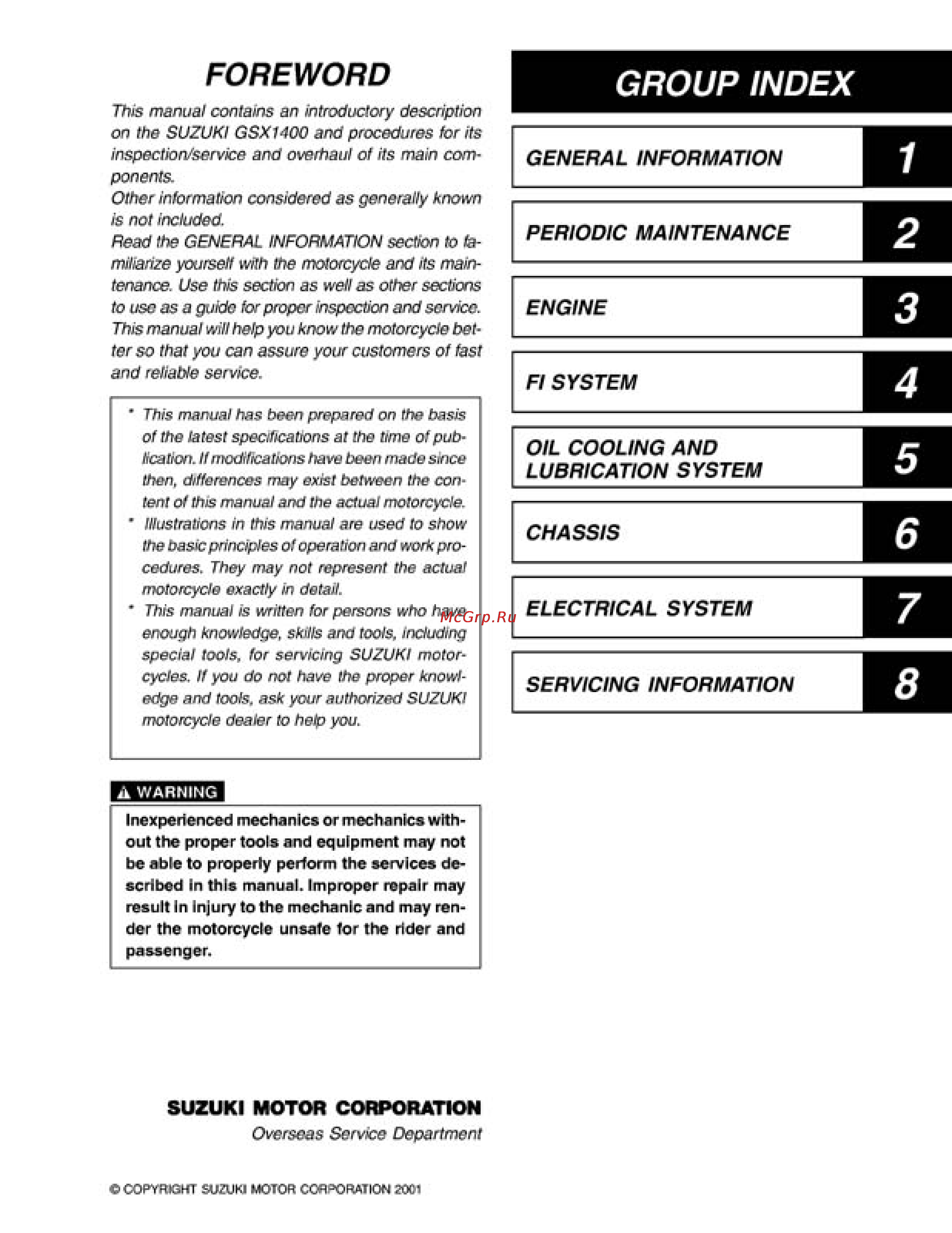
FOREWORD GROUP INDEX This manual contains an introductory description on the SUZUKI GSXI400 and procedures tor its inspection service and overhaul of its main com ponents Other information considered as generally known is not included Read the GENERAL INFORMATION section to fa miliarize yourself with the motorcycle and its main tenance Use this section as well as other sections to use as a guide for proper inspection and service This manual will help you know the motorcycle bet ter so that you can assure your customers of fast and reliable service This manual has been prepared on the basis of the latest specifications at the time of pub lication If modifications have been made since then differences may exist between the con tent of this manual and the actual motorcycle Illustrations in this manual are used to show the basic principles of operation and work pro cedures They may not represent the actual motorcycle exactly in detail This manual is written for persons who have enough knowledge skills and tools including special tools for servicing SUZUKI motor cycles If you do not have the proper knowl edge and tools ask your authorized SUZUKI motorcycle dealer to help you A WARNING Inexperienced out the mechanics proper tools or and mechanics equipment may with not be able to properly perform the services de scribed In this manual Improper repair may result In Injury to the mechanic and may ren der the motorcycle unsafe for the rider and passenger SUZUKI MOTOR CORPORATION Overseas Service Department COPYRIGHT SUZUKI MOTOR CORPORATION 2001 GENERAL INFORMATION PERIODIC MAINTENANCE ENGINE Fl SYSTEM OIL COOLING AND LUBRICATION SYSTEM CHASSIS ELECTRICAL SYSTEM SERVICING INFORMATION