![Tp-Link TL-SG5426 [364/499] Show interfaces status](/img/pdf.png)
Tp-Link TL-SG5426 [364/499] Show interfaces status


![Tp-Link TL-SG5426 [364/499] Show interfaces status](/views2/1042695/page364/bg16c.png)
Interface Commands
4-123
4
Command Mode
Privileged Exec
Command Usage
Statistics are only initialized for a power reset. This command sets the base
value for displayed statistics to zero for the current management session.
However, if you log out and back into the management interface, the statistics
displayed will show the absolute value accumulated since the last power reset.
Example
The following example clears statistics on port 5.
show interfaces status
This command displays the status for an interface.
Syntax
show interfaces status [interface]
interface
• ethernet unit/port
- unit - Stack unit. (Range: Unit 1)
- port - Port number. (Range: 1-26)
• port-channel channel-id (Range: 1-4)
• vlan vlan-id (Range: 1-4094)
Default Setting
Shows the status for all interfaces.
Command Mode
Normal Exec, Privileged Exec
Command Usage
If no interface is specified, information on all interfaces is displayed. For a
description of the items displayed by this command, see “Displaying
Connection Status” on page 3-76.
Console#clear counters ethernet 1/5
Console#
Содержание
- Port gigabit managed switch p.1
- Tl sg5426 p.1
- Copyright trademarks p.2
- Fcc statement p.3
- Ce mark warning p.3
- Contents p.4
- Tables p.18
- Figures p.22
- This switch provides a broad range of features for layer 2 switching it includes a management agent that allows you to configure the features listed in this manual the default configuration can be used for most of the features provided by this switch however there are many options that you should configure to maximize the switch s performance for your particular network environment p.26
- Table 1 1 key features p.26
- Key features p.26
- Chapter 1 introduction p.26
- Introduction p.27
- Description of software features p.27
- Description of software features p.28
- Be used to provide independent priorities for delay sensitive data and best effort data p.29
- Introduction p.29
- Description of software features p.30
- The switch s system defaults are provided in the configuration file factory_default_config cfg to reset the switch defaults this file should be set as the startup configuration file page 3 19 p.31
- The following table lists some of the basic system defaults p.31
- Table 1 2 system defaults p.31
- System defaults p.31
- Introduction p.31
- Table 1 2 system defaults continued p.32
- System defaults p.32
- Table 1 2 system defaults continued p.33
- Introduction p.33
- Connecting to the switch p.34
- Configuration options p.34
- Chapter 2 initial configuration p.34
- Required connections p.35
- Initial configuration p.35
- Remote connections p.36
- Console connection p.36
- Basic configuration p.36
- Setting passwords p.37
- Setting an ip address p.37
- Manual configuration p.37
- Initial configuration p.37
- Dynamic configuration p.38
- Basic configuration p.38
- At the interface configuration mode prompt use one of the following commands p.38
- Initial configuration p.39
- Enabling snmp management access p.39
- Community strings for snmp version 1 and 2c clients p.39
- Trap receivers p.40
- Basic configuration p.40
- Configuring access for snmp version 3 clients p.41
- Saving configuration settings p.41
- Initial configuration p.41
- Using the web interface p.43
- Chapter 3 configuring the switch p.43
- Navigating the web browser interface p.44
- Home page p.44
- Configuring the switch p.44
- Tl sg5426 p.45
- The web agent displays an image of the switch s ports the mode can be set to display different information for the ports including active i e up or down duplex i e half or full duplex or flow control i e with or without flow control clicking on the image of a port opens the port configuration page as described on page 3 78 p.45
- Panel display p.45
- Notes 1 p.45
- Navigating the web browser interface p.45
- Configuration options p.45
- Configurable parameters have a dialog box or a drop down list once a configuration change has been made on a page be sure to click on the apply button to confirm the new setting the following table summarizes the web page configuration buttons p.45
- Main menu p.46
- Configuring the switch p.46
- Using the onboard web agent you can define system parameters manage and control the switch and all its ports or monitor network conditions the following table briefly describes the selections available from this program p.46
- Navigating the web browser interface p.47
- Configuring the switch p.48
- Navigating the web browser interface p.49
- Configuring the switch p.50
- Navigating the web browser interface p.51
- Displaying system information p.52
- Configuring the switch p.52
- Basic configuration p.52
- Managing system files p.53
- The main board and management software as well as the power status of the system p.54
- Displaying switch hardware software versions p.54
- Basic configuration p.54
- Figure 3 4 switch information p.55
- Configuring the switch p.55
- Cli use the following command to display version information p.55
- Web click system switch information p.55
- Displaying bridge extension capabilities p.56
- Basic configuration p.56
- Setting the switch s ip address p.57
- Configuring the switch p.57
- Web click system ip configuration select the vlan through which the management station is attached set the ip address mode to static enter the ip address subnet mask and gateway then click apply p.58
- Manual configuration p.58
- Figure 3 6 manual ip configuration p.58
- Cli specify the management interface ip address and default gateway p.58
- Basic configuration p.58
- Using dhcp bootp p.59
- Configuring the switch p.59
- Managing firmware p.60
- Enabling jumbo frames p.60
- Basic configuration p.60
- Configuring the switch p.61
- The file name should not contain slashes or p.61
- Downloading system software from a server p.61
- Saving or restoring configuration settings p.62
- Basic configuration p.62
- The file name should not contain slashes or p.63
- Downloading configuration settings from a server p.63
- Configuring the switch p.63
- Console port settings p.64
- Basic configuration p.64
- Configuring the switch p.65
- Telnet status enables or disables telnet access to the switch default enabled telnet port number sets the tcp port number for telnet on the switch default 23 login timeout sets the interval that the system waits for a user to log into the cli if a login attempt is not detected within the timeout interval the connection is terminated for the session range 0 300 seconds default 300 seconds p.66
- Telnet settings p.66
- Exec timeout sets the interval that the system waits until user input is detected if user input is not detected within the timeout interval the current session is terminated range 0 65535 seconds default 600 seconds password threshold sets the password intrusion threshold which limits the number of failed logon attempts when the logon attempt threshold is reached the p.66
- Command attributes p.66
- Cli enter line configuration mode for the console then specify the connection parameters as required to display the current console port settings use the show line command from the normal exec level p.66
- Basic configuration p.66
- You can access the onboard configuration program over the network using telnet i e a virtual terminal management access via telnet can be enabled disabled and other various parameters set including the tcp port number timeouts and a password these parameters can be configured via the web or cli interface p.66
- Configuring the switch p.67
- Web click system log logs p.68
- The switch allows you to control the logging of error messages including the type of events that are recorded in switch memory logging to a remote system log syslog server and displays a list of recent event messages p.68
- The logs page allows you to scroll through the logged system and event messages the switch can store up to 2048 log entries in temporary random access memory ram i e memory flushed on power reset and up to 4096 entries in permanent flash memory p.68
- Displaying log messages p.68
- Configuring event logging p.68
- Cli enter line configuration mode for a virtual terminal then specify the connection parameters as required to display the current virtual terminal settings use the show line command from the normal exec level p.68
- Basic configuration p.68
- System log configuration p.69
- Configuring the switch p.69
- Set the level of event messages to be logged to ram and flash memory then click apply p.70
- Remote log configuration p.70
- Basic configuration p.70
- Simple mail transfer protocol p.71
- Configuring the switch p.71
- Basic configuration p.72
- Resetting the system p.73
- Renumbering the system p.73
- Configuring the switch p.73
- Setting the system clock p.74
- Configuring sntp p.74
- Basic configuration p.74
- Setting the time zone p.75
- Configuring the switch p.75
- Simple network management protocol p.76
- Setting community access strings p.76
- Specifying trap managers and trap types p.77
- Configuring the switch p.77
- Simple network management protocol p.78
- Enabling snmp agent status p.78
- Configuring snmpv3 management access p.79
- Setting the local engine id p.79
- Configuring the switch p.79
- Specifying a remote engine id p.80
- Simple network management protocol p.80
- Configuring snmpv3 users p.80
- Configuring the switch p.81
- Web click snmp snmpv3 users click new to configure a user name in the new user page define a name and assign it to a group then click add to save the configuration and return to the user name list to delete a user check the box next to the user name then click delete to change the assigned group of a user click change group in the actions column of the users table and select the new group p.82
- Simple network management protocol p.82
- Figure 3 29 configuring snmpv3 users p.82
- Cli use the snmp server user command to configure a new user name and assign it to a group p.82
- Configuring the switch p.83
- Configuring remote snmpv3 users p.83
- Simple network management protocol p.84
- Configuring snmpv3 groups p.84
- Notify view the configured view for notifications range 1 64 characters p.85
- Configuring the switch p.85
- Simple network management protocol p.86
- Web click snmp snmpv3 groups click new to configure a new group in the new group page define a name assign a security model and level and then select read and write views click add to save the new group and return to the groups list to delete a group check the box next to the group name then click delete p.87
- Figure 3 31 configuring snmpv3 groups p.87
- Configuring the switch p.87
- Cli use the snmp server group command to configure a new group specifying the security model and level and restricting mib access to defined read and write views p.87
- Simple network management protocol p.88
- Setting snmpv3 views p.88
- User authentication p.89
- Configuring user accounts p.89
- Configuring the switch p.89
- User authentication p.90
- Configuring the switch p.91
- Configuring local remote logon authentication p.91
- User authentication p.92
- Configuring the switch p.93
- Cli specify all the required parameters to enable logon authentication p.94
- User authentication p.94
- Configuring the switch p.95
- Configuring https p.95
- When you log onto the web interface using https for secure access a secure sockets layer ssl certificate appears for the switch by default the certificate that netscape and internet explorer display will be associated with a warning that the site is not recognized as a secure site this is because the certificate has not been signed by an approved certification authority if you want this warning to be replaced by a message confirming that the connection to the switch is secure you must obtain a unique certificate and a private key and password from a recognized certification authority p.96
- When you have obtained these place them on your tftp server and use the following command at the switch s command line interface to replace the default unrecognized certificate with an authorized one p.96
- User authentication p.96
- The switch must be reset for the new certificate to be activated to reset the switch type p.96
- Replacing the default secure site certificate p.96
- For maximum security we recommend you obtain a unique secure sockets layer certificate at the earliest opportunity this is because the default certificate for the switch is not unique to the hardware you have purchased p.96
- Cli this example enables the http secure server and modifies the port number p.96
- Caution p.96
- Configuring the switch p.97
- Configuring the secure shell p.97
- User authentication p.98
- Configuring the switch p.99
- Configuring the ssh server p.99
- User authentication p.100
- Generating the host key pair p.100
- Web click security ssh host key settings select the host key type from the drop down box select the option to save the host key from memory to flash if required prior to generating the key and then click generate p.101
- Configuring the switch p.101
- Cli this example generates a host key pair using both the rsa and dsa p.101
- Algorithms stores the keys to flash memory and then displays the host s public keys p.101
- User authentication p.102
- Configuring port security p.102
- Configuring the switch p.103
- Configuring 802 x port authentication p.103
- User authentication p.104
- Displaying 802 x global settings p.104
- Command attributes p.105
- Cli this example shows the default global setting for 802 x p.105
- Cli this example enables 802 x globally for the switch p.105
- 802 x system authentication control sets the global setting for 802 x default disabled p.105
- Web select security 802 x configuration enable 802 x globally for the switch and click apply p.105
- Web click security 802 x information p.105
- The 802 x protocol provides port authentication the 802 x protocol must be enabled globally for the switch system before port settings are active p.105
- Figure 3 40 802 x global configuration p.105
- Figure 3 39 802 x global information p.105
- Configuring the switch p.105
- Configuring 802 x global settings p.105
- Waits before re transmitting an eap packet range 1 65535 default 30 seconds p.106
- User authentication p.106
- Configuring port settings for 802 x p.106
- User authentication p.108
- Cli this example sets the 802 x parameters on port 2 for a description of the additional fields displayed in this example see show dot1x on page 4 86 p.108
- Web select security 802 x statistics select the required port and then click query click refresh to update the statistics p.109
- This switch can display statistics for dot1x protocol exchanges for any port p.109
- Displaying 802 x statistics p.109
- Configuring the switch p.109
- Configuring access control lists p.110
- Access control lists p.110
- Setting the acl name and type p.111
- Configuring the switch p.111
- Configuring an extended ip acl p.112
- Configuring a standard ip acl p.112
- Access control lists p.112
- Configuring the switch p.113
- Access control lists p.114
- Configuring the switch p.115
- Configuring a mac acl p.115
- Binding a port to an access control list p.116
- Access control lists p.116
- Filtering ip addresses for management access p.117
- Configuring the switch p.117
- Access control lists p.118
- Port configuration p.119
- Displaying connection status p.119
- Configuring the switch p.119
- Shows the current speed and duplex mode auto or fixed choice p.120
- Port configuration p.120
- Configuring the switch p.121
- Configuring interface connections p.121
- Port configuration p.122
- Creating trunk groups p.123
- Configuring the switch p.123
- Statically configuring a trunk p.124
- Statically configured p.124
- Port configuration p.124
- Active links p.124
- Enabling lacp on selected ports p.125
- Configuring the switch p.125
- Port configuration p.126
- Then the port admin key must be set to the same value for a port to be allowed to join a channel group p.127
- System priority lacp system priority is used to determine link aggregation group lag membership and to identify this device to other switches during lag negotiations range 0 65535 default 32768 ports must be configured with the same system priority to join the same lag p.127
- Set port actor this menu sets the local side of an aggregate link i e the ports on this switch p.127
- Ports assigned to a common port channel must meet the following criteria ports must have the same lacp system priority ports must have the same lacp port admin key p.127
- Port port number range 1 26 p.127
- Note if the port channel admin key lacp admin key 4 135 is not set through the cli when a channel group is formed i e it has a null value of 0 this key is set to the same value as the port admin key used by the interfaces that joined the group lacp admin key as described in this section and on 4 134 p.127
- However if the port channel admin key is set p.127
- Dynamically creating a port channel p.127
- Configuring the switch p.127
- Configuring lacp parameters p.127
- Command attributes p.127
- Cli the following example enables lacp for ports 1 to 6 just connect these ports to lacp enabled trunk ports on another switch to form a trunk p.127
- This device after you have completed setting the port lacp parameters click apply p.128
- Port configuration p.128
- Cli the following example configures lacp parameters for ports 1 4 ports 1 4 are used as active members of the lag p.129
- You can display statistics for lacp protocol messages p.129
- Table 3 7 lacp port counters p.129
- Marker sent number of valid marker pdus transmitted from this channel group p.129
- Marker received number of valid marker pdus received by this channel group p.129
- Lacpdus sent number of valid lacpdus transmitted from this channel group p.129
- Lacpdus received number of valid lacpdus received on this channel group p.129
- Field description p.129
- Displaying lacp port counters p.129
- Configuring the switch p.129
- Table 3 7 lacp port counters continued p.130
- Port configuration p.130
- Marker unknown pkts number of frames received that either 1 carry the slow protocols ethernet type value but contain an unknown pdu or 2 are addressed to the slow protocols group mac address but do not carry the slow protocols ethernet type p.130
- Marker illegal pkts number of frames that carry the slow protocols ethernet type value but contain a badly formed pdu or an illegal value of protocol subtype p.130
- Figure 3 54 lacp port counters information p.130
- Field description p.130
- Cli the following example displays lacp counters p.130
- Web click port lacp port counters information select a member port to display the corresponding information p.130
- You can display configuration settings and the operational state for the local side of an link aggregation p.131
- Long timeout periodic transmission of lacpdus uses a slow transmission rate lacp activity activity control value with regard to this link 0 passive 1 active p.131
- Displaying lacp settings and status for the local side p.131
- Configuring the switch p.131
- Web click port lacp port internal information select a port channel to display the corresponding information p.132
- Port configuration p.132
- Figure 3 55 lacp port internal information p.132
- Cli the following example displays the lacp configuration settings and operational state for the local side of port channel 1 p.132
- You can display configuration settings and the operational state for the remote side of an link aggregation p.133
- Web click port lacp port neighbors information select a port channel to display the corresponding information p.133
- Displaying lacp settings and status for the remote side p.133
- Configuring the switch p.133
- Setting broadcast storm thresholds p.134
- Port configuration p.134
- Cli specify any interface and then enter the threshold the following disables broadcast storm control for port 1 and then sets broadcast suppression at 500 packets per second for port 2 p.135
- Web click port port trunk broadcast control set the threshold mark the enabled field for the desired interface and click apply p.135
- Figure 3 57 port broadcast control p.135
- Configuring the switch p.135
- Port configuration p.136
- Configuring port mirroring p.136
- Rate limit configuration p.137
- Configuring the switch p.137
- Configuring rate limits p.137
- You can display standard statistics on network traffic from the interfaces group and ethernet like mibs as well as a detailed breakdown of traffic based on the rmon mib interfaces and ethernet like statistics display errors on the traffic passing through each port this information can be used to identify potential problems with the switch such as a faulty port or unusually heavy loading rmon statistics provide access to a broad range of statistics including a total count of different frame types and sizes passing through each port all values displayed have been accumulated since the last system reboot and are shown as counts per second statistics are refreshed every 60 seconds by default p.138
- Showing port statistics p.138
- Port configuration p.138
- Cli this example sets the rate limit level for input traffic passing through port 3 p.138
- Configuring the switch p.139
- Port configuration p.140
- Configuring the switch p.141
- Address table settings p.142
- Setting static addresses p.142
- Displaying the address table p.143
- Configuring the switch p.143
- Web click address table dynamic addresses specify the search type i e mark the interface mac address or vlan checkbox select the method of sorting the displayed addresses and then click query p.144
- Figure 3 62 configuring a dynamic address table p.144
- Cli this example also displays the address table entries for port 1 p.144
- Address table settings p.144
- Spanning tree algorithm configuration p.145
- Configuring the switch p.145
- Changing the aging time p.145
- Spanning tree algorithm configuration p.146
- Configuring the switch p.147
- Spanning tree algorithm configuration p.148
- Displaying global settings p.148
- Configuring the switch p.149
- Configuring global settings p.150
- This command displays global sta settings followed by settings for each por p.150
- Spanning tree algorithm configuration p.150
- Configuring the switch p.151
- Spanning tree algorithm configuration p.152
- Web click spanning tree sta configuration modify the required attributes and click apply p.153
- Figure 3 65 configuring spanning tree p.153
- Configuring the switch p.153
- Cli this example enables spanning tree protocol sets the mode to rstp and then configures the sta and rstp parameters p.153
- Spanning tree algorithm configuration p.154
- Displaying interface settings p.154
- Configuring the switch p.155
- Web click spanning tree sta port information or sta trunk information p.156
- The amount of frame flooding required to rebuild address tables during reconfiguration events does not cause the spanning tree to reconfigure when the interface changes state and also overcomes other sta related timeout problems however remember that edge port should only be enabled for ports connected to an end node device admin link type the link type attached to this interface point to point a connection to exactly one other bridge shared a connection to two or more bridges auto the switch automatically determines if the interface is attached to a point to point link or to shared media p.156
- Spanning tree algorithm configuration p.156
- Figure 3 66 displaying spanning tree port information p.156
- Cli this example shows the sta attributes for port 5 p.156
- Configuring the switch p.157
- Configuring interface settings p.157
- Spanning tree algorithm configuration p.158
- Configuring the switch p.159
- Configuring multiple spanning trees p.159
- Spanning tree algorithm configuration p.160
- The mstp port information and mstp trunk information pages display the current status of ports and trunks in the selected mst instance p.161
- Mst instance id instance identifier to configure default 0 p.161
- Displaying interface settings for mstp p.161
- Configuring the switch p.161
- Command attributes p.161
- Cli this example sets sta attributes for port 1 followed by settings for each port p.161
- Spanning tree algorithm configuration p.162
- Configuring the switch p.163
- Configuring interface settings for mstp p.163
- Cli this displays sta settings for instance 0 followed by settings for each port the settings for instance 0 are global settings that apply to the ist the settings for other instances only apply to the local spanning tree p.163
- You can configure the sta interface settings for an mst instance using the mstp port configuration and mstp trunk configuration pages p.163
- The following attributes are read only and cannot be changed p.163
- Sta state displays current state of this port within the spanning tree p.163
- For additional information p.163
- Field attributes p.163
- Spanning tree algorithm configuration p.164
- Vlan configuration p.165
- Ieee 802 q vlans p.165
- Configuring the switch p.165
- Vlan configuration p.166
- Assigning ports to vlans p.166
- Configuring the switch p.167
- Vlan configuration p.168
- Forwarding tagged untagged frames p.168
- Enabling or disabling gvrp global setting p.168
- Configuring the switch p.169
- Displaying current vlans p.169
- Displaying basic vlan information p.169
- Vlan configuration p.170
- Creating vlans p.171
- Configuring the switch p.171
- You can also use the vlan static membership by port page to configure vlan groups based on the port index page 3 131 however note that this configuration page can only add ports to a vlan as tagged members p.172
- Web click vlan 802 q vlan static list to create a new vlan enter the vlan id and vlan name mark the enable checkbox to activate the vlan and then click add p.172
- Vlan configuration p.172
- Use the vlan static table to configure port members for the selected vlan index assign ports as tagged if they are connected to 802 q vlan compliant devices or untagged they are not connected to any vlan aware devices or configure a port as forbidden to prevent the switch from automatically adding it to a vlan via the gvrp protocol notes 1 p.172
- Figure 3 74 configuring a vlan static list p.172
- Cli this example creates a new vlan p.172
- Adding static members to vlans vlan index p.172
- Configuring the switch p.173
- Vlan configuration p.174
- Adding static members to vlans port index p.174
- Configuring the switch p.175
- Vlan id assigned to untagged frames received on the interface default 1 p.175
- Ingress filtering does not affect vlan independent bpdu frames such as gvrp or stp however they do affect vlan dependent bpdu frames such as gmrp p.175
- Configuring vlan behavior for interfaces p.175
- Configuring ieee 802 q tunneling p.176
- Configuring the switch p.177
- Configuring ieee 802 q tunneling p.178
- Configuring the switch p.179
- Enabling qinq tunneling on the switch p.180
- Configuring ieee 802 q tunneling p.180
- Configuring the switch p.181
- Adding an interface to a qinq tunnel p.181
- Configuring ieee 802 q tunneling p.182
- Configuring the switch p.183
- Cli this example sets port 1 to tunnel access mode indicates that the tpid used for 802 q tagged frames is 9100 hexadecimal and sets port 2 to tunnel uplink mode p.183
- Configuring private vlans p.184
- Configuring ieee 802 q tunneling p.184
- Enabling private vlans p.184
- Protocol vlans p.185
- Protocol vlan group configuration p.185
- Configuring uplink and downlink ports p.185
- Configuring the switch p.185
- Configuring protocol vlan interfaces p.186
- Configuring ieee 802 q tunneling p.186
- Setting the default priority for interfaces p.187
- Layer 2 queue settings p.187
- Configuring the switch p.187
- Class of service configuration p.187
- Mapping cos values to egress queues p.188
- Figure 3 84 port priority configuration p.188
- Cli this example assigns a default priority of 5 to port 3 p.188
- Class of service configuration p.188
- 2 0 3 4 5 6 7 p.188
- Web click priority default port priority or default trunk priority modify the default priority for any interface then click apply p.188
- This switch processes class of service cos priority tagged traffic by using four priority queues for each port with service schedules based on strict or weighted round robin wrr up to eight separate traffic priorities are defined in ieee 802 p the default priority levels are assigned according to recommendations in the ieee 802 p standard as shown in the following table p.188
- Table 3 11 mapping cos values to egress queues p.188
- Web cl p.189
- Traffic clas p.189
- The priority levels recommended in the ieee 802 p standard for various network applications are shown in the following table however you can map the priority levels to the switch s output queues in any way that benefits application traffic for your own network p.189
- Select a port or trunk for the current mapping of cos values to output queues to be displayed assign priorities to the traffic classes i e output queues then click apply p.189
- Priority cos value range 0 7 where 7 is the highest priority p.189
- Output queue buffer range 0 3 where 3 is the highest cos priority queue p.189
- Configuring the switch p.189
- Command attributes p.189
- Selecting the queue mode p.190
- Enabling cos p.190
- Class of service configuration p.190
- Setting the service weight for traffic classes p.191
- Configuring the switch p.191
- Selecting ip precedence dscp priority p.192
- Mapping layer 3 4 priorities to cos values p.192
- Layer 3 4 priority settings p.192
- Class of service configuration p.192
- Mapping ip precedence p.193
- Configuring the switch p.193
- Web click priority ip precedence priority select an entry from the ip precedence priority table enter a value in the class of service value field and then click apply p.194
- Mapping specific values for ip precedence is implemented as an interface configuration command but any changes will apply to the all interfaces on the switch p.194
- Figure 3 90 mapping ip precedence priority values p.194
- Cli the following example globally enables ip precedence service on the switch maps ip precedence value 1 to cos value 0 on port 1 and then displays the ip precedence settings p.194
- Class of service configuration p.194
- The dscp is six bits wide allowing coding for up to 64 different forwarding behaviors the dscp retains backward compatibility with the three precedence bits so that non dscp compliant will not conflict with the dscp mapping based on network policies different kinds of traffic can be marked for different kinds of forwarding the dscp default values are defined in the following table note that all the dscp values that are not specified are mapped to cos value 0 p.195
- Mapping dscp priority p.195
- Dscp priority table shows the dscp priority to cos map class of service value maps a cos value to the selected dscp priority value note that 0 represents low priority and 7 represent high priority p.195
- Configuring the switch p.195
- Command attributes p.195
- Web click priority ip dscp priority select an entry from the dscp table enter a value in the class of service value field then click apply p.195
- You can also map network applications to class of service values based on the ip port number i e tcp udp port number in the frame header some of the more common tcp service ports include http 80 ftp 21 telnet 23 and pop3 110 p.196
- Web click priority ip port priority status set ip port priority status to enabled p.196
- Mapping ip port priority p.196
- Ip port priority status enables or disables the ip port priority ip port priority table shows the ip port to cos map ip port number tcp udp set a new ip port number class of service value sets a cos value for a new ip port note that 0 represents low priority and 7 represent high priority p.196
- Figure 3 92 ip port priority status p.196
- Command attributes p.196
- Cli the following example globally enables dscp priority service on the switch maps dscp value 0 to cos value 1 on port 1 and then displays the dscp priority settings p.196
- Class of service configuration p.196
- Quality of service p.197
- Configuring the switch p.197
- Quality of service p.198
- Configuring quality of service parameters p.198
- Configuring a class map p.198
- Configuring the switch p.199
- Quality of service p.200
- Creating qos policies p.201
- Configuring the switch p.201
- Quality of service p.202
- Web click qos diffserv policy map to display the list of existing policy maps to add a new policy map click add policy to configure the policy rule settings click edit classes p.203
- Figure 3 95 configuring policy maps p.203
- Configuring the switch p.203
- Cli this example creates a policy map called rd policy sets the average bandwidth the 1 mbps the burst rate to 1522 bps and the response to reduce the dscp value for violating packets to 0 p.203
- Quality of service p.204
- Attaching a policy map to ingress queues p.204
- Multicast filtering p.205
- Layer 2 igmp snooping and query p.205
- Configuring the switch p.205
- Multicast filtering p.206
- Configuring igmp snooping and query parameters p.206
- Configuring the switch p.207
- Cli this example modifies the settings for multicast filtering and then displays the current status p.207
- Web click igmp snooping igmp configuration adjust the igmp settings as required and then click apply the default settings are shown below p.207
- The igmp snooping immediate leave feature enables a layer 2 lan interface to be removed from the multicast forwarding table without first sending an igmp group specific query to the interface upon receiving a group specific igmpv2 leave message the switch immediately removes the interface from the layer 2 forwarding table entry for that multicast group unless a multicast router was learned on the port p.207
- Igmp immediate leave improves bandwidth management for all hosts in a switched network p.207
- Figure 3 97 igmp configuration p.207
- Enabling igmp immediate leave p.207
- Multicast filtering p.208
- Displaying interfaces attached to a multicast router p.208
- Specifying static interfaces for a multicast router p.209
- Configuring the switch p.209
- Multicast filtering p.210
- Displaying port members of multicast services p.210
- Configuring the switch p.211
- Assigning ports to multicast services p.211
- Multicast filtering p.212
- Igmp filtering and throttling p.212
- Configuring the switch p.213
- Enabling igmp filtering and throttling p.213
- Multicast filtering p.214
- Configuring igmp filtering and throttling for interfaces p.214
- When you have created an igmp profile number you can then configure the multicast groups to filter and set the access mode p.215
- Web click igmp snooping igmp filter throttling port configuration or igmp filter throttling trunk configuration select a profile to assign to an interface then set the throttling number and action click apply p.215
- Figure 3 104 igmp filter and throttling port configuration p.215
- Each profile has only one access mode either permit or deny when the access mode is set to permit igmp join reports are processed when a multicast group falls within the controlled range when the access mode is set to p.215
- Configuring the switch p.215
- Configuring igmp filter profiles p.215
- Command usage p.215
- Cli this example assigns igmp profile number 19 to port 1 and then sets the throttling number and action the current igmp filtering and throttling settings for the interface are then displayed p.215
- Multicast filtering p.216
- Multicast filtering p.217
- Configuring global mvr settings p.217
- Multicast vlan registration p.218
- Configuring the switch p.218
- Displaying mvr interface status p.219
- Configuring the switch p.219
- Web click mvr port or trunk information p.220
- Multicast filtering p.220
- Figure 3 107 mvr port information p.220
- Cli this example shows information about interfaces attached to the mvr vlan p.220
- Displaying port members of multicast groups p.221
- Configuring the switch p.221
- Multicast filtering p.222
- Configuring mvr interface status p.222
- Configuring the switch p.223
- Assigning static multicast groups to interfaces p.223
- Configuring general dns service parameters p.224
- Configuring domain name service p.224
- Configuring the switch p.225
- Configuring domain name service p.226
- Configuring static dns host to address entries p.226
- Web select dns static host table enter a host name and one or more corresponding addresses then click apply p.227
- Figure 3 112 dns static host table p.227
- Configuring the switch p.227
- Cli this example maps two address to a host name and then configures an alias host name for the same addresses p.227
- Displaying the dns cache p.228
- Configuring domain name service p.228
- Dhcp snooping p.229
- Configuring the switch p.229
- Dhcp snooping configuration p.230
- Dhcp snooping p.230
- Dhcp snooping vlan configuration p.231
- Dhcp snooping information option configuration p.231
- Configuring the switch p.231
- Dhcp snooping port configuration p.232
- Dhcp snooping p.232
- Dhcp snooping binding information p.233
- Configuring the switch p.233
- Ip source guard port configuration p.234
- Ip source guard p.234
- Static ip source guard binding configuration p.235
- Configuring the switch p.235
- Ip source guard p.236
- Dynamic ip source guard binding information p.236
- Switch clustering p.237
- Configuring the switch p.237
- Switch clustering p.238
- Cluster configuration p.238
- Configuring the switch p.239
- Cluster member configuration p.239
- Switch clustering p.240
- Cluster member information p.240
- Configuring the switch p.241
- Cluster candidate information p.241
- Using the command line interface p.242
- Console connection p.242
- Chapter 4 command line interface p.242
- Accessing the cli p.242
- Telnet connection p.243
- Command line interface p.243
- Minimum abbreviation p.244
- Keywords and arguments p.244
- Getting help on commands p.244
- Entering commands p.244
- Command completion p.244
- Showing commands p.245
- If you enter a at the command prompt the system will display the first level of keywords for the current command class normal exec or privileged exec or configuration class global acl interface line or vlan database you can also display a list of valid keywords for a specific command for example the command show displays a list of possible show commands p.245
- Command line interface p.245
- Using command history p.246
- Understanding command modes p.246
- Partial keyword lookup p.246
- Negating the effect of commands p.246
- Entering commands p.246
- To enter privileged exec mode enter the following user names and passwords p.247
- Table 4 1 command modes p.247
- Exec commands p.247
- Command prompt only a limited number of the commands are available in this mode you can access all commands only from the privileged exec command mode or administrator mode to access privilege exec mode open a new console session with the user name and password admin the system will now display the console command prompt you can also enter privileged exec mode from within normal exec mode by entering the enable command followed by the privileged level password super page 4 26 p.247
- Command line interface p.247
- Interface configuration these commands modify the port configuration such as speed duplex and negotiation line configuration these commands modify the console port and telnet configuration and include command such as parity and databits vlan configuration includes the command to create vlan groups p.248
- Global configuration these commands modify the system level configuration and include commands such as hostname and snmp server community access control list configuration these commands are used for packet filtering p.248
- For example you can use the following commands to enter interface configuration mode and then return to privileged exec mode p.248
- Entering commands p.248
- Configuration commands are privileged level commands used to modify switch settings these commands modify the running configuration only and are not saved when the switch is rebooted to store the running configuration in non volatile storage use the copy running config startup config command p.248
- Configuration commands p.248
- To enter the other modes at the configuration prompt type one of the following commands use the exit or end command to return to the privileged exec mode p.248
- To enter the global configuration mode enter the command configure in privileged exec mode the system prompt will change to console config which gives you access privilege to all global configuration commands p.248
- The configuration commands are organized into different modes p.248
- Table 4 2 configuration modes p.248
- Table 4 3 command line processing p.249
- Commands are not case sensitive you can abbreviate commands and parameters as long as they contain enough letters to differentiate them from any other currently available commands or parameters you can use the tab key to complete partial commands or enter a partial command followed by the character to display a list of possible matches you can also use the following editing keystrokes for command line processing p.249
- Command line processing p.249
- Command line interface p.249
- The system commands can be broken down into the functional groups shown belo p.250
- Table 4 4 command groups p.250
- Command groups p.250
- The access mode shown in the following tables is indicated by these abbreviations p.251
- Table 4 5 line commands p.251
- Line commands p.251
- Command line interface p.251
- Acl access control list configuration mst multiple spanning tree cm class map configuration ne normal exec gc global configuration pe privileged exec ic interface configuration pm policy map configuration lc line configuration vc vlan database configuration p.251
- You can access the onboard configuration program by attaching a vt100 compatible device to the server s serial port these commands are used to set communication parameters for the serial port or telnet i e a virtual terminal p.251
- Line commands p.252
- Password p.253
- Command line interface p.253
- Timeout login response p.254
- Line commands p.254
- Exec timeout p.254
- Password thresh p.255
- Command line interface p.255
- Silent time p.256
- Line commands p.256
- Databits p.256
- Parity p.257
- Command line interface p.257
- Stopbits p.258
- Line commands p.258
- Show line p.259
- Disconnect p.259
- Command line interface p.259
- This command activates privileged exec mode in privileged mode additional commands are available and certain commands display additional information see understanding command modes on page 4 5 p.260
- The device has two predefined privilege levels 0 normal exec 15 privileged exec enter level 15 to access privileged exec mode p.260
- Table 4 6 general commands p.260
- Syntax enable level p.260
- Level privilege level to log into the device p.260
- General commands p.260
- Example to show all lines enter this command p.260
- Enable p.260
- Disable p.261
- Command line interface p.261
- Show history p.262
- General commands p.262
- Configure p.262
- Reload p.263
- Command line interface p.263
- General commands p.264
- System management commands p.265
- Prompt p.265
- Device designation commands p.265
- Command line interface p.265
- Username p.266
- User access commands p.266
- System management commands p.266
- Hostname p.266
- Enable password p.267
- Command line interface p.267
- System management commands p.268
- Management p.268
- Ip filter commands p.268
- Show management p.269
- Command line interface p.269
- Web server commands p.270
- This command specifies the tcp port number used by the web browser interface use the no form to use the default port p.270
- Table 4 12 web server commands p.270
- System management commands p.270
- Syntax ip http port port number no ip http port p.270
- Port number the tcp port to be used by the browser interface range 1 65535 p.270
- Ip http port p.270
- Example p.270
- Default setting 80 p.270
- Command mode global configuration p.270
- Ip http server p.271
- Ip http secure server p.271
- Command line interface p.271
- Ip http secure port p.272
- System management commands p.272
- Telnet server commands p.273
- Ip telnet port p.273
- Command line interface p.273
- System management commands p.274
- Secure shell commands p.274
- Ip telnet server p.274
- To use the ssh server complete these steps p.275
- The ssh server on this switch supports both password and public key authentication if password authentication is specified by the ssh client then the password can be authenticated either locally or via a radius or tacacs remote authentication server as specified by the authentication login command on page 4 71 if public key authentication is specified by the client then you must configure authentication keys on both the client and the switch as described in the following section note that regardless of whether you use public key or password authentication you still have to generate authentication keys on the switch and enable the ssh server p.275
- Table 4 15 ssh commands continued p.275
- Provide host public key to clients many ssh client programs automatically import the host public key during the initial connection setup with the switch otherwise you need to manually create a known hosts file on the management station and place the host public key in it an entry for a public key in the known hosts file would appear similar to the following example p.275
- Import client s public key to the switch use the copy tftp public key command to copy a file containing the public key for all the ssh client s granted management access to the switch note that these clients must be configured locally on the switch via the user accounts page as described on page 3 46 the clients are subsequently authenticated using these keys the current p.275
- Generate a host key pair use the ip ssh crypto host key generate command to create a host public private key pair p.275
- Command line interface p.275
- System management commands p.276
- Ip ssh server p.276
- Ip ssh timeout p.277
- Command line interface p.277
- System management commands p.278
- Ip ssh server key size p.278
- Ip ssh authentication retries p.278
- Ip ssh crypto host key generate p.279
- Delete public key p.279
- Command line interface p.279
- System management commands p.280
- Ip ssh save host key p.280
- Ip ssh crypto zeroize p.280
- Show ssh p.281
- Show ip ssh p.281
- Command line interface p.281
- System management commands p.282
- Show public key p.282
- Example p.283
- Command line interface p.283
- This command controls logging of error messages sending debug or error messages to switch memory the no form disables the logging process p.284
- Table 4 17 event logging commands p.284
- System management commands p.284
- Syntax no logging on p.284
- Related commands logging history 4 44 clear logging 4 46 p.284
- Logging on p.284
- Example p.284
- Event logging commands p.284
- Default setting none p.284
- Command usage the logging process controls error messages saved to switch memory you can use the logging history command to control the type of error messages that are stored p.284
- Command mode global configuration p.284
- Logging history p.285
- Command line interface p.285
- Logging facility p.286
- System management commands p.286
- Logging host p.286
- Logging trap p.287
- Command line interface p.287
- Clear logging p.287
- System management commands p.288
- Show logging p.288
- Show log p.289
- Command line interface p.289
- System management commands p.290
- Syntax no logging sendmail host ip_address p.290
- Smtp alert commands p.290
- Logging sendmail host p.290
- Ip_address ip address of an smtp server that will be sent alert messages for event handling p.290
- Example p.290
- Default setting p.290
- This command specifies smtp servers that will be sent alert messages use the no form to remove an smtp server p.290
- These commands configure smtp event handling and forwarding of alert messages to the specified smtp servers and email recipients p.290
- The following example shows sample messages stored in ram p.290
- Table 4 21 smtp alert commands p.290
- Logging sendmail level p.291
- Command line interface p.291
- System management commands p.292
- Logging sendmail source email p.292
- Logging sendmail destination email p.292
- Show logging sendmail p.293
- Logging sendmail p.293
- Command line interface p.293
- Disabled p.294
- Default setting p.294
- Command usage the time acquired from time servers is used to record accurate dates and times for log events without sntp the switch only records the time starting from the factory default set at the last bootup i e 00 00 00 jan 1 2001 this command enables client time requests to time servers specified via the sntp servers command it issues time synchronization requests based on the interval set via the sntp poll command p.294
- Command mode p.294
- Time commands p.294
- This command enables sntp client requests for time synchronization from ntp or sntp time servers specified with the sntp servers command use the no form to disable sntp client requests p.294
- The system clock can be dynamically set by polling a set of specified time servers ntp or sntp maintaining an accurate time on the switch enables the system log to record meaningful dates and times for event entries if the clock is not set the switch will only record the time from the factory default set at the last bootup p.294
- Table 4 22 time commands p.294
- System management commands p.294
- Syntax p.294
- Sntp client p.294
- No sntp client p.294
- Global configuration p.294
- Sntp server p.295
- Command line interface p.295
- System management commands p.296
- Sntp poll p.296
- Show sntp p.296
- Clock timezone p.297
- Calendar set p.297
- Command line interface p.297
- This example shows how to set the system clock to 15 12 34 april 1st 2004 p.298
- This command displays the system clock p.298
- This command displays the configuration file stored in non volatile memory that is used to start up the system p.298
- Table 4 23 system status commands p.298
- System status commands p.298
- System management commands p.298
- Show startup config p.298
- Show calendar p.298
- Example p.298
- Default setting none p.298
- Command mode privileged exec p.298
- Command mode normal exec privileged exec p.298
- Example p.299
- Command usage use this command in conjunction with the show running config command to compare the information in running memory to the information stored in non volatile memory p.299
- Command line interface p.299
- This command displays settings for key command modes each mode group is separated by symbols and includes the configuration mode command and corresponding commands this command displays the following information p.299
- Snmp community strings users names and access levels vlan database vlan id name and state vlan configuration settings for each interface ip address configured for the switch spanning tree settings any configured settings for the console port and telnet p.299
- System management commands p.300
- Show running config p.300
- Related commands show startup config 4 57 p.301
- Example p.301
- Command line interface p.301
- This command displays system information p.302
- System management commands p.302
- Shows all active console and telnet sessions including user name idle time and ip address of telnet client p.302
- Show users p.302
- Show system p.302
- Example p.302
- Default setting none p.302
- Command usage for a description of the items shown by this command refer to displaying system information on page 3 10 the post results should all display pass if any post test indicates fail contact your distributor for assistance p.302
- Command mode normal exec privileged exec p.302
- This command displays hardware and software version information for the system p.303
- Show version p.303
- Example p.303
- Default setting p.303
- Command usage the session used to execute this command is indicated by a symbol next to the line i e session index number p.303
- Command usage see displaying switch hardware software versions on page 3 11 for detailed information on the items displayed by this command p.303
- Command mode normal exec privileged exec p.303
- Command line interface p.303
- System management commands p.304
- Jumbo frame p.304
- Frame size commands p.304
- Flash file commands p.305
- Command line interface p.305
- Flash file commands p.306
- Example the following example shows how to upload the configuration settings to a file on the tftp server p.307
- Command line interface p.307
- This example shows how to copy a secure site certificate from a tftp server it then reboots the switch to activate the certificate p.307
- The following example shows how to download a configuration file p.307
- The following example shows how to copy the running configuration to a startup file p.307
- Flash file commands p.308
- Delete p.308
- Command line interface p.309
- Whichboot p.310
- Flash file commands p.310
- Boot system p.310
- Command line interface p.311
- Authentication sequence p.311
- Authentication commands p.311
- Authentication login p.312
- Authentication commands p.312
- Command line interface p.313
- Authentication enable p.313
- Table 4 29 radius client commands p.314
- Remote authentication dial in user service radius is a logon authentication protocol that uses software running on a central server to control access to radius aware devices on the network an authentication server contains a database of multiple user name password pairs with associated privilege levels for each user or group that require management access to a switch p.314
- Related commands enable password sets the password for changing command modes 4 26 p.314
- Radius client p.314
- Example p.314
- Command usage radius uses udp while tacacs uses tcp udp only offers best effort delivery while tcp offers a connection oriented transport also note that radius encrypts only the password in the access request packet from the client to the server while tacacs encrypts the entire body of the packet radius and tacacs logon authentication assigns a specific privilege level for each user name and password pair the user name password and privilege level must be configured on the authentication server you can specify three authentication methods in a single command to indicate the authentication sequence for example if you enter authentication enable radius tacacs local the user name and password on the radius server is verified first if the radius server is not available then authentication is attempted on the tacacs server if the tacacs server is not available the local user name and password is checked p.314
- Authentication commands p.314
- Radius server port p.315
- Radius server host p.315
- Command line interface p.315
- Radius server retransmit p.316
- Radius server key p.316
- Authentication commands p.316
- Show radius server p.317
- Radius server timeout p.317
- Command line interface p.317
- Tacacs server port p.318
- Tacacs server host p.318
- Tacacs client p.318
- Authentication commands p.318
- Tacacs server key p.319
- Show tacacs server p.319
- Command line interface p.319
- Port security commands p.320
- Port security p.320
- Authentication commands p.320
- Command line interface p.321
- Dot1x system auth control p.322
- Disabled p.322
- Default setting p.322
- Command mode p.322
- Authentication commands p.322
- X port authentication p.322
- This command enables 802 x port authentication globally on the switch use the no form to restore the default p.322
- The switch supports ieee 802 x dot1x port based access control that prevents unauthorized access to the network by requiring users to first submit credentials for authentication client authentication is controlled centrally by a radius server using eap extensible authentication protocol p.322
- Table 4 32 802 x port authentication p.322
- Syntax p.322
- No dotx system auth control p.322
- Global configuration p.322
- Example p.322
- Dot1x port control p.323
- Dot1x max req p.323
- Dot1x default p.323
- Command line interface p.323
- Dot1x operation mode p.324
- Authentication commands p.324
- Dot1x re authenticate p.325
- Command line interface p.325
- Dot1x timeout quiet period p.325
- Dot1x re authentication p.325
- Dot1x timeout tx period p.326
- Dot1x timeout re authperiod p.326
- Authentication commands p.326
- Show dot1x p.327
- Command line interface p.327
- Connecting authenticating authenticated aborting p.328
- Authentication commands p.328
- Example p.329
- Command line interface p.329
- Access control list commands p.330
- Ip acls p.331
- Command line interface p.331
- Access list ip p.331
- Access control list commands p.332
- Permit deny standard acl p.332
- Permit deny extended acl p.332
- Command line interface p.333
- Show ip access list p.334
- Ip access group p.334
- Access control list commands p.334
- Mac acls p.335
- Access list mac p.335
- Access control list commands p.335
- Permit deny mac acl p.336
- Command line interface p.336
- Show mac access list p.337
- Access control list commands p.337
- Show mac access group p.338
- Mac access group p.338
- Command line interface p.338
- Show ip access group p.339
- Command line interface p.339
- This command shows the port assignments of acls p.340
- This command shows all acls and associated rules as well as all the user defined masks p.340
- Table 4 36 acl information p.340
- Show access list p.340
- Show access group p.340
- Privileged executive p.340
- Privileged exec p.340
- Once the acl is bound to an interface i e the acl is active the order in which the rules are displayed is determined by the associated mask p.340
- Example p.340
- Command usage p.340
- Command mode p.340
- Acl information p.340
- Access control list commands p.340
- Command line interface p.341
- Table 4 37 snmp commands p.341
- Snmp version 3 also provides security features that cover message integrity authentication and encryption as well as controlling user access to specific areas of the mib tree to use snmpv3 first set an snmp engine id or accept the default specify read and write access views for the mib tree configure snmp user groups with the required security model i e snmp v1 v2c or v3 and security level i e authentication and privacy and then assign snmp users to these groups along with their specific authentication and privacy passwords p.341
- Snmp commands p.341
- Controls access to this switch from management stations using the simple network management protocol snmp as well as the error types sent to trap managers p.341
- Snmp server p.342
- Snmp commands p.342
- Show snmp p.342
- Snmp server community p.343
- Command line interface p.343
- Snmp server location p.344
- Snmp server contact p.344
- Snmp commands p.344
- Snmp server host p.345
- Command line interface p.345
- Snmp commands p.346
- Command line interface p.347
- Snmp server enable traps p.347
- Snmp server engine id p.348
- Snmp commands p.348
- Show snmp engine id p.349
- Command line interface p.349
- This command adds an snmp view which controls user access to the mib use the p.350
- Snmp server view p.350
- Snmp commands p.350
- Form to remove an snmp view p.350
- Snmp server group p.351
- Show snmp view p.351
- Command line interface p.351
- When privacy is selected the des 56 bit algorithm is used for data encryption for additional information on the notification messages supported by this switch see supported notification messages on page 5 13 also note that the authentication link up and link down messages are legacy traps and must therefore be enabled in conjunction with the p.352
- Snmp commands p.352
- Command page 4 106 p.352
- Command line interface p.353
- Show snmp group p.353
- Four default groups are provided snmpv1 read only access and read write access and snmpv2c read only access and read write access p.353
- Example p.353
- Command mode privileged exec p.353
- Snmp server user p.354
- Snmp commands p.354
- Digests from the user s password if the remote engine id is not first configured p.355
- Command line interface p.355
- This command shows information on snmp users p.356
- Table 4 41 show snmp user display description p.356
- Snmp commands p.356
- Show snmp user p.356
- Example p.356
- Command mode privileged exec p.356
- Default setting p.357
- Command line interface p.357
- This command configures an interface type and enter interface configuration mode use the no form to remove a trunk p.357
- These commands are used to display or set communication parameters for an ethernet port aggregated link or vlan p.357
- Table 4 42 interface commands p.357
- Syntax p.357
- Interface interface no interface port channel channel id p.357
- Interface commands p.357
- Interface p.357
- Ethernet unit port unit stack unit range unit 1 port port number range 1 26 port channel channel id range 1 4 vlan vlan id range 1 4094 p.357
- Speed duplex p.358
- Interface commands p.358
- Description p.358
- Negotiation p.359
- Command line interface p.359
- Interface commands p.360
- Capabilities p.360
- Command line interface p.361
- Flowcontrol p.361
- Shutdown p.362
- Interface commands p.362
- Switchport broadcast packet rate p.363
- Command line interface p.363
- Clear counters p.363
- Show interfaces status p.364
- Interface commands p.364
- Show interfaces counters p.365
- Command line interface p.365
- Show interfaces switchport p.366
- Interface commands p.366
- This example shows the configuration setting for port 24 p.367
- Table 4 43 interfaces switchport statistics p.367
- Example p.367
- Command line interface p.367
- Port monitor p.368
- Mirror port commands p.368
- Show port monitor p.369
- Command line interface p.369
- Rate limit commands p.370
- Rate limit p.370
- Table 4 46 link aggregation commands p.371
- Ports can be statically grouped into an aggregate link i e trunk to increase the bandwidth of a network connection or to ensure fault recovery or you can use the link aggregation control protocol lacp to automatically negotiate a trunk link between this switch and another network device for static trunks the switches have to comply with the cisco etherchannel standard for dynamic trunks the switches have to comply with lacp this switch supports up to 32 trunks for example a trunk consisting of two 1000 mbps ports can support an aggregate bandwidth of 4 gbps when operating at full duplex p.371
- Link aggregation commands p.371
- Command line interface p.371
- Link aggregation commands p.372
- Channel group p.372
- Command line interface p.373
- Link aggregation commands p.374
- Lacp system priority p.374
- Command line interface p.375
- Lacp admin key ethernet interface p.375
- Link aggregation commands p.376
- Lacp admin key port channel p.376
- Show lacp p.377
- Lacp port priority p.377
- Command line interface p.377
- Marker received number of valid marker pdus received by this channel group p.378
- Link aggregation commands p.378
- Lacpdus unknown pkts number of frames received that either 1 carry the slow protocols ethernet type value but contain an unknown pdu or 2 are addressed to the slow protocols group mac address but do not carry the slow protocols ethernet type p.378
- Lacpdus sent number of valid lacpdus transmitted from this channel group p.378
- Lacpdus received number of valid lacpdus received on this channel group p.378
- Lacpdus illegal pkts number of frames that carry the slow protocols ethernet type value but contain a badly formed pdu or an illegal value of protocol subtype p.378
- Field description p.378
- Example p.378
- Default setting p.378
- Command mode p.378
- Table 4 47 show lacp counters display description p.378
- Privileged exec p.378
- Port channel all p.378
- Marker sent number of valid marker pdus transmitted from this channel group p.378
- Table 4 48 show lacp internal display description p.379
- Long timeout periodic transmission of lacpdus uses a slow transmission rate lacp activity activity control value with regard to this link 0 passive 1 active p.379
- Command line interface p.379
- Table 4 50 show lacp sysid display description p.380
- Table 4 49 show lacp neighbors display description p.380
- Link aggregation commands p.380
- Mac address table static p.381
- Command line interface p.381
- Address table commands p.381
- Show mac address table p.382
- Clear mac address table dynamic p.382
- Address table commands p.382
- Mac address table aging time p.383
- Command line interface p.383
- Show mac address table aging time p.384
- Address table commands p.384
- This section includes commands that configure the spanning tree algorithm sta globally for the switch and commands that configure sta for the selected interface p.385
- Table 4 52 spanning tree commands p.385
- Spanning tree commands p.385
- Command line interface p.385
- Spanning tree mode p.386
- Spanning tree commands p.386
- Spanning tree p.386
- Spanning tree forward time p.387
- Command line interface p.387
- Spanning tree hello time p.388
- Spanning tree commands p.388
- Command line interface p.389
- Spanning tree priority p.389
- Spanning tree max age p.389
- Spanning tree pathcost method p.390
- Spanning tree commands p.390
- Spanning tree transmission limit p.391
- Spanning tree mst configuration p.391
- Command line interface p.391
- Spanning tree commands p.392
- Mst vlan p.392
- Mst priority p.392
- Command line interface p.393
- Spanning tree commands p.394
- Revision p.394
- Max hops p.394
- Spanning tree cost p.395
- Command line interface p.395
- Spanning tree spanning disabled p.395
- Spanning tree port priority p.396
- Spanning tree commands p.396
- Spanning tree portfast p.397
- Spanning tree edge port p.397
- Command line interface p.397
- Spanning tree link type p.398
- Spanning tree commands p.398
- Spanning tree mst cost p.399
- Command line interface p.399
- Spanning tree mst port priority p.400
- Spanning tree commands p.400
- Spanning tree protocol migration p.401
- Show spanning tree p.401
- Command line interface p.401
- Spanning tree commands p.402
- This command shows the configuration of the multiple spanning tree p.403
- Show spanning tree mst configuration p.403
- Example p.403
- Command mode privileged exec p.403
- Command line interface p.403
- Vlan commands p.404
- Gvrp and bridge extension commands p.404
- Show bridge ext p.405
- Command line interface p.405
- Bridge ext gvrp p.405
- Vlan commands p.406
- Switchport gvrp p.406
- Show gvrp configuration p.406
- Show garp timer p.407
- Garp timer p.407
- Command line interface p.407
- Vlan database p.408
- Vlan commands p.408
- Editing vlan groups p.408
- Command line interface p.409
- The following example adds a vlan using vlan id 105 and name rd5 the vlan is activated by default p.410
- Table 4 56 configuring vlan interfaces p.410
- Syntax p.410
- Show vlan 4 175 p.410
- Related commands p.410
- Interface vlan vlan id p.410
- Interface vlan p.410
- Global configuration p.410
- Example p.410
- Default setting p.410
- Configuring vlan interfaces p.410
- Command mode p.410
- Vlan id id of the configured vlan range 1 4094 no leading zeroes p.410
- Vlan commands p.410
- This command enters interface configuration mode for vlans which is used to configure vlan parameters for a physical interface p.410
- Switchport mode p.411
- Command line interface p.411
- Vlan commands p.412
- Switchport ingress filtering p.412
- Switchport acceptable frame types p.412
- Switchport native vlan p.413
- Command line interface p.413
- Vlan commands p.414
- Switchport allowed vlan p.414
- Switchport forbidden vlan p.415
- Command line interface p.415
- Show vlan p.416
- Displaying vlan information p.416
- Vlan commands p.416
- Dot1q tunnel system tunnel control p.417
- Configuring ieee 802 q tunneling p.417
- Command line interface p.417
- Vlan commands p.418
- Switchport dot1q tunnel mode p.418
- Switchport dot1q tunnel tpid p.419
- Show dot1q tunnel p.419
- Related commands p.419
- Command line interface p.419
- Switchport dot1q tunnel mode 4 177 p.420
- Related commands p.420
- Pvlan up link interface list down link interface list no pvlan p.420
- Private vlans provide port based security and isolation between ports within the assigned vlan this section describes commands used to configure private vlans p.420
- Example p.420
- Configuring private vlans p.420
- Vlan commands p.420
- This command enables or configures a private vlan use the no form to disable the private vlan p.420
- Table 4 59 private vlan commands p.420
- Syntax p.420
- Show pvlan p.421
- Private vlans and normal vlans can exist simultaneously within the same switch p.421
- Command line interface p.421
- Vlan commands p.422
- Protocol vlan protocol group configuring groups p.422
- Configuring protocol based vlans p.422
- Protocol vlan protocol group configuring interfaces p.423
- Command line interface p.423
- Vlan commands p.424
- Show protocol vlan protocol group p.424
- Show interfaces protocol vlan protocol group p.424
- Command line interface p.425
- Priority commands layer 2 p.425
- Priority commands p.425
- Switchport priority default p.426
- Queue mode p.426
- Priority commands p.426
- Queue bandwidth p.427
- Command line interface p.427
- Queue cos map p.428
- Priority commands p.428
- Show queue mode p.429
- Show queue bandwidth p.429
- Command line interface p.429
- Show queue cos map p.430
- Priority commands layer 3 and 4 p.430
- Priority commands p.430
- Map ip dscp global configuration p.430
- Map ip dscp interface configuration p.431
- Command line interface p.431
- Show map ip dscp p.432
- Priority commands p.432
- The commands described in this section are used to configure differentiated services diffserv classification criteria and service policies you can classify traffic based on access lists ip precedence or dscp values or vlans using access lists allows you select traffic based on layer 2 layer 3 or layer 4 information contained in each packet p.433
- Related commands p.433
- Quality of service commands p.433
- Map ip dscp global configuration 4 189 map ip dscp interface configuration 4 190 p.433
- Example p.433
- Command line interface p.433
- Use the class map command to designate a class name for a specific category of traffic and enter the class map configuration mode 2 use the match command to select a specify type of traffic based on an access list a dscp or ip precedence value or a vlan 3 set an acl mask to enable filtering for the criteria specified in the match command 4 use the policy map command to designate a policy name for a specific manner in which ingress traffic will be handled and enter the policy map configuration mode 5 use the class command to identify the class map and enter policy map class configuration mode a policy map can contain multiple class statements 6 use the set command to modify the qos value for matching traffic class and use the policer command to monitor the average flow and burst rate and drop any traffic that exceeds the specified rate or just reduce the dscp service level for traffic exceeding the specified rate 7 use the service policy command to assign a policy map to a specific inte p.434
- To create a service policy for a specific category of ingress traffic follow these steps p.434
- Table 4 66 quality of service commands p.434
- Quality of service commands p.434
- Notes 1 p.434
- Class map p.435
- Command line interface p.435
- Quality of service commands p.436
- Policy map p.436
- You must create a class map page 4 195 before assigning it to a policy map p.437
- Command line interface p.437
- Quality of service commands p.438
- New precedence new ip precedence value p.438
- New precedence p.438
- New dscp p.438
- New cos p.438
- Rate kbps burst byte p.439
- Rate kbp p.439
- Police p.439
- Command line interface p.439
- Policy map nam p.440
- Class map name p.440
- Show class map p.440
- Service policy p.440
- Quality of service commands p.440
- Policy map name p.440
- Show policy map interface p.441
- Show policy map p.441
- Policy map name p.441
- Policy map nam p.441
- Interface p.441
- Command line interface p.441
- Class map name p.441
- Multicast filtering commands p.442
- Igmp snooping commands p.442
- Example p.442
- Ip igmp snooping p.443
- Command line interface p.443
- Ip igmp snooping vlan static p.443
- Multicast filtering commands p.444
- Ip igmp snooping version p.444
- Ip igmp snooping leave proxy p.444
- Show ip igmp snooping p.445
- Ip igmp snooping immediate leave p.445
- Command line interface p.445
- Show mac address table multicast p.446
- Multicast filtering commands p.446
- Ip igmp snooping query count p.447
- Ip igmp snooping querier p.447
- Igmp query commands layer 2 p.447
- Command line interface p.447
- Multicast filtering commands p.448
- Ip igmp snooping query interval p.448
- Command line interface p.449
- Ip igmp snooping router port expire time p.449
- Ip igmp snooping query max response time p.449
- Static multicast routing commands p.450
- Multicast filtering commands p.450
- Ip igmp snooping vlan mrouter p.450
- The following shows how to configure port 11 as a multicast router port within vlan 1 p.451
- Show ip igmp snooping mrouter p.451
- Command line interface p.451
- Multicast filtering commands p.452
- Ip igmp filter global configuration p.452
- In certain switch applications the administrator may want to control the multicast services that are available to end users for example an ip tv service based on a specific subscription plan the igmp filtering feature fulfills this requirement by restricting access to specified multicast services on a switch port and igmp throttling limits the number of simultaneous multicast groups a port can join p.452
- Igmp filtering and throttling commands p.452
- Disabled p.452
- Default setting p.452
- Command usage igmp filtering enables you to assign a profile to a switch port that specifies multicast groups that are permitted or denied on the port an igmp filter profile can contain one or more or a range of multicast addresses but only one profile can be assigned to a port when enabled igmp join reports received on the port are checked against the filter profile if a requested multicast group is permitted the igmp join report is forwarded as normal if a requested multicast group is denied the igmp join report is dropped igmp filtering and throttling only applies to dynamically learned multicast groups it does not apply to statically configured groups p.452
- Command mode global configuration p.452
- This command globally enables igmp filtering and throttling on the switch use the no form to disable the feature p.452
- Table 4 71 igmp filtering and throttling commands p.452
- Syntax p.452
- No ip igmp filter p.452
- Permit deny p.453
- Ip igmp profile p.453
- Command line interface p.453
- Multicast filtering commands p.454
- Ip igmp filter interface configuration p.454
- Ip igmp max groups p.455
- Command line interface p.455
- Show ip igmp filter p.456
- Multicast filtering commands p.456
- Ip igmp max groups action p.456
- Show ip igmp profile p.457
- Command line interface p.457
- Show ip igmp throttle interface p.457
- Using this command without specifying an interface displays all interfaces p.458
- This section describes commands used to configure multicast vlan registration mvr a single network wide vlan can be used to transmit multicast traffic such as television channels across a service provider s network any multicast traffic entering an mvr vlan is sent to all subscribers this can significantly reduce to processing overhead required to dynamically monitor and establish the distribution tree for a normal multicast vlan also note that mvr maintains the user isolation and data security provided by vlan segregation by passing only multicast traffic into other vlans to which the subscribers belong p.458
- Table 4 72 multicast vlan registration commands p.458
- Privileged exec p.458
- Port port number range 1 29 port channel channel id range 1 4 p.458
- Multicast vlan registration commands p.458
- Multicast filtering commands p.458
- Example p.458
- Default setting p.458
- Command usage p.458
- Command mode p.458
- Mvr global configuration p.459
- Command line interface p.459
- Mvr interface configuration p.460
- Multicast filtering commands p.460
- Command line interface p.461
- Show mvr p.462
- Multicast filtering commands p.462
- The following shows information about the interfaces associated with multicast groups assigned to the mvr vlan p.463
- The following displays information about the interfaces attached to the mvr vlan p.463
- Table 4 75 show mvr members display description p.463
- Table 4 74 show mvr interface display description p.463
- Command line interface p.463
- Ip interface commands p.464
- Ip address p.464
- Ip default gateway p.465
- Command line interface p.465
- Show ip redirects p.466
- Command line interface p.466
- Ip source guard commands p.467
- Ip source guard p.467
- Command line interface p.468
- Ip source guard commands p.469
- Ip source guard binding p.469
- Show ip source guard binding p.470
- Show ip source guard p.470
- Command line interface p.470
- Ip dhcp snooping p.471
- Dhcp snooping commands p.471
- Command line interface p.472
- Ip dhcp snooping vlan p.473
- Dhcp snooping commands p.473
- Ip dhcp snooping trust p.474
- Command line interface p.474
- Ip dhcp snooping verify mac address p.475
- Ip dhcp snooping information option p.475
- Dhcp snooping commands p.475
- Ip dhcp snooping information policy p.476
- Command line interface p.476
- Switch cluster commands p.477
- Show ip dhcp snooping binding p.477
- Show ip dhcp snooping p.477
- This command enables clustering on the switch use the no form to disable clustering p.478
- Table 4 79 switch cluster commands p.478
- Syntax no cluster p.478
- Example p.478
- Enabled p.478
- Default setting p.478
- Command usage to create a switch cluster first be sure that clustering is enabled on the switch the default is enabled then set the switch as a cluster commander set a cluster ip pool that does not conflict with any other ip subnets in the network cluster ip addresses are assigned to switches when they become members and are used for communication between member switches and the commander switch clusters are limited to a single ip subnet layer 2 domain a switch can only be a member of one cluster configured switch clusters are maintained across power resets and network changes p.478
- Command mode global configuration p.478
- Command line interface p.478
- Cluster p.478
- Cluster commander p.479
- Switch cluster commands p.479
- Cluster ip pool p.479
- Rcommand p.480
- Command line interface p.480
- Cluster member p.480
- This command shows the switch clustering configuration p.481
- This command shows the current switch cluster members p.481
- Switch cluster commands p.481
- Show cluster members p.481
- Show cluster p.481
- Example p.481
- Command mode privileged exec p.481
- Show cluster candidates p.482
- Example p.482
- Command mode privileged exec p.482
- Command line interface p.482
- This command shows the discovered candidate switches in the network p.482
- Software features p.483
- Appendix a software specifications p.483
- Standards p.484
- Software specifications p.484
- Management features p.484
- Management information bases p.485
- Problems accessing the management interface p.487
- Appendix b troubleshooting p.487
- Using system logs p.488
- Troubleshooting p.488
- Domain name service dns p.489
- Differentiated services code point service dscp p.489
- Class of service cos p.489
- Boot protocol bootp bootp is p.489
- Access control list acl p.489
- Glossary 1 p.489
- Glossary p.489
- Extensible authentication protocol over lan eapol p.489
- Dynamic host control protocol dhcp p.489
- Ieee 802 x p.490
- Ieee 802 q p.490
- Ieee 802 p p.490
- Ieee 802 d p.490
- Ieee 802 ac p.490
- Group attribute registration protocol garp p.490
- Glossary 2 p.490
- Glossary p.490
- Generic multicast registration protocol gmrp p.490
- Generic attribute registration protocol garp p.490
- Garp vlan registration protocol gvrp p.490
- Glossary p.491
- Md5 message digest algorithm p.491
- Management information base mib p.491
- Link aggregation control protocol lacp p.491
- Link aggregation p.491
- Layer 2 p.491
- Ip multicast filtering p.491
- Internet group management protocol igmp p.491
- In band management p.491
- Igmp snooping p.491
- Igmp query p.491
- Glossary 3 p.491
- Out of band management p.492
- Network time protocol ntp p.492
- Multicast switching p.492
- Glossary 4 p.492
- Glossary p.492
- Remote monitoring rmon p.492
- Remote authentication dial in user service radius radius p.492
- Rapid spanning tree protocol rstp rst p.492
- Private vlans p.492
- Port trunk p.492
- Port mirroring p.492
- Port authentication p.492
- Transmission control protocol internet protocol tcp ip p.493
- Terminal access controller access control system plus tacacs tacacs p.493
- Telnet p.493
- Spanning tree algorithm sta p.493
- Simple network time protocol sntp sntp p.493
- Simple network management protocol snmp p.493
- Secure shell ssh p.493
- Glossary 5 p.493
- Glossary p.493
- User datagram protocol udp udp p.493
- Trivial file transfer protocol tftp p.493
- Xmodem p.494
- Virtual lan vlan p.494
- Glossary 6 p.494
- Glossary p.494
- Show ip interface p.495
- Ip interface commands p.495
- Ip dhcp restart p.495
- Numerics p.496
- Index 1 p.496
- Index 2 p.497
- Index 3 p.498
- Index 4 p.499
Похожие устройства
-
 Tp-Link TL-SG108Инструкция по эксплуатации
 -
 Tp-Link TL-SF1005DРуководство по быстрому старту
 -
 Tp-Link TL-SF1005P 5x100Mb 4PoE 58W неуправляемыйРуководство по эксплуатации
 -
Tp-Link TL-SG1005P 5G 4PoE+ 65W неуправляемыйРуководство по эксплуатации
-
Tp-Link LS1008G V2Инструкция по эксплуатации
-
Tp-Link LS1008 8x100Mb неуправляемыйИнструкция по эксплуатации
-
Tp-Link LS1005 5x100Mb неуправляемыйИнструкция по эксплуатации
-
Tp-Link TL-SG1005LP 5G 4PoE+ 40W неуправляемыйРуководство по эксплуатации
-
Tp-Link TL-SF1005LP 5x100Mb 4PoE 41W неуправляемыйРуководство по эксплуатации
-
 Tp-Link TL-SL1226P 24x100Mb 2G 24PoE+ 250W неуправляемыйРуководство по эксплуатации
 -
 Tp-Link TL-SF1006P 6x100Mb 4PoE+ 67W неуправляемыйРуководство по эксплуатации
 -
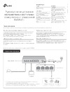 Tp-Link TL-SF1008LP 8x100Mb 4PoE 41W неуправляемыйРуководство по эксплуатации