
Pioneer DEH-2430R Руководство по установке онлайн
Nota:
• Antes de finalmente instalar la unidad, conecte el
cableado temporalmente y asegúrese de que todo
esté conectado correctamente y que la unidad y
el sistema funcionan debidamente.
• Utilice sólo las piezas que se incluyen con esta
unidad para asegurar la instalación adecuada. El
uso de piezas no autorizadas podría causar fallos
de funcionamiento.
• Consulte con su distribuidor si la instalación
requiere del taladro de orificios u otras modifica-
ciones del vehículo.
• Instale la unidad donde no alcance el espacio del
conductor, y donde no pueda dañar a los
pasajeros si sucediera un paro repentino, como
una detención de emergencia.
• El semiconductor láser se dañará si se sobre-
calienta, por eso no instale la unidad en un lugar
caliente – por ejemplo, cerca de la salida de un
calefactor.
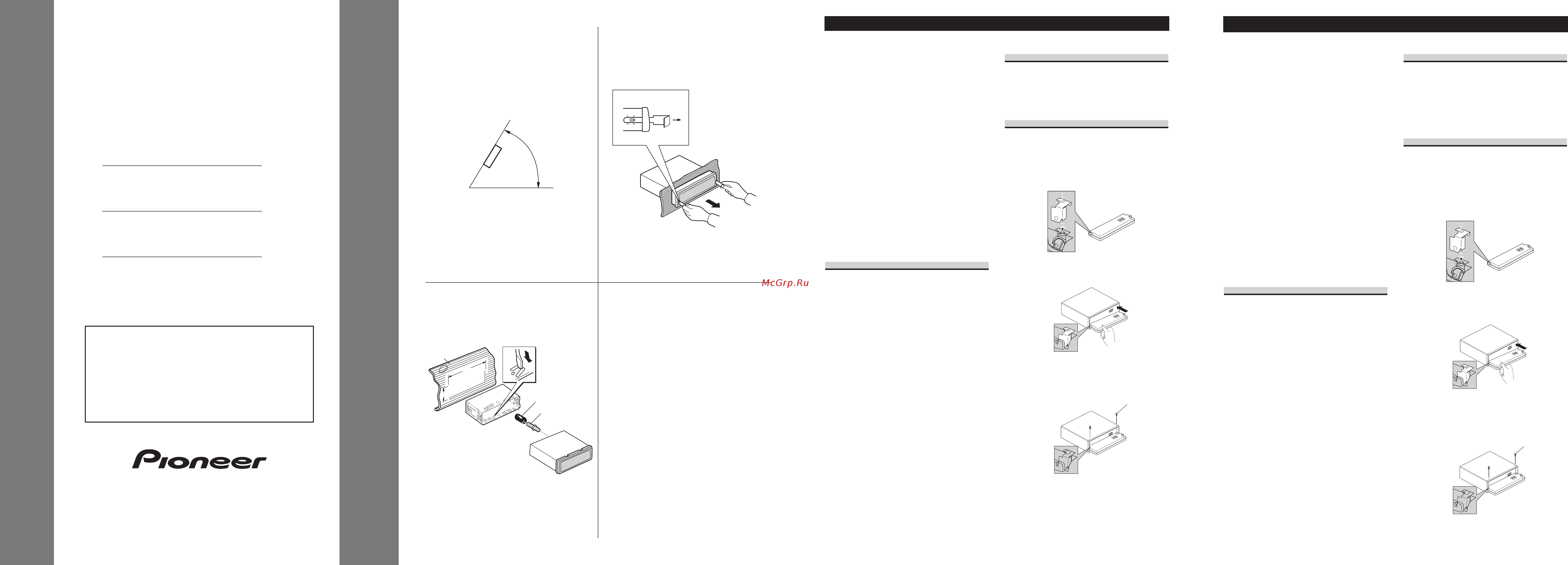
• Si el ángulo de la instalación excede los 60° del
lado horizontal, la unidad podría no brindar su
óptimo funcionamiento. (Fig. 1)
Instalación con tope de goma
(Fig. 2)
1. Tablero de instrumentos
2. Soporte
Después de insertar el soporte en la tabla de
mandos, luego seleccione las orejetas apropiadas
según el grosor del material de la tabla de man-
dos y dóblelos.
(Instale lo más firme posible usando las lengüe-
tas superior e inferior. Para fijar, doble las
lengüetas 90 grados.)
3. Tope de goma
4. Tornillo
Quitado de la unidad (Fig. 3)
5. Inserte las herramientas de extracción suminis-
tradas en la unidad, como se indica en la figura,
hasta que se enganchen en su positión.
Tire de la unidad mientras mantiene las her-
ramientas presionadas contra los lados de la
unidad.
Colocación del panel delantero
Si no desea utilizar la función de extracción y
colocación del panel delantero, utilice los tornil-
los de fijación suministrados y fije el panel
delantero a esta unidad.
1.
Coloque lo sujetadore en el panel
delantero.
2. Reinstale el panel delantero en la
unidad.
3. Fije el panel delantero a la unidad
utilizando los tornillos de fijación.
Instalación <ESPAÑOL>
Note:
• Before finally installing the unit, connect the
wiring temporarily, making sure it is all connect-
ed up properly, and the unit and the system work
properly.
• Use only the parts included with the unit to
ensure proper installation. The use of unautho-
rized parts can cause malfunctions.
• Consult with your nearest dealer if installation
requires the drilling of holes or other modifica-
tions of the vehicle.
• Install the unit where it does not get in the dri-
ver’s way and cannot injure the passenger if there
is a sudden stop, like an emergency stop.
• The semiconductor laser will be damaged if it
overheats, so don’t install the unit anywhere hot
— for instance, near a heater outlet.
• If installation angle exceeds 60° from horizontal,
the unit might not give its optimum performance.
(Fig. 1)
Installation with the rubber bush
(Fig. 2)
1. Dashboard
2. Holder
After inserting the holder into the dashboard,
then select the appropriate tabs according to the
thickness of the dashboard material and bend
them.
(Install as firmly as possible using the top and
bottom tabs. To secure, bend the tabs 90
degrees.)
3. Rubber bush
4. Screw
Removing the Unit (Fig. 3)
5. Insert the supplied extraction keys into the unit,
as shown in the figure, until they click into place.
Keeping the keys pressed against the sides of the
unit, pull the unit out.
Fixing the Front Panel
If you do not operate the Removing and
Attaching the Front Panel Function, use the sup-
plied fixing screws and fix the front panel to this
unit.
1.
Attach the holder to the front panel.
2. Replace the front panel to the unit.
3. Fix the front panel to the unit using
fixing screws.
Installation <ENGLISH>
INSTALLATION MANUAL
MANUEL D’INSTALLATION
60°
5
Fig. 1
Abb. 1
Afb. 1
Fig. 2
Abb. 2
Afb. 2
53
182
1
2
3
4
<KSNZX/01G00001>
DEH-3400R
DEH-2460R
DEH-2430R
Printed in
Imprimé
<CRD3500-A/JS> EW
This product conforms to new cord colors.
Los colores de los cables de este producto se confor-
man con un nuevo código de colores.
Dieses Produkt entspricht den neuen kabelfarben.
Le code de couleur des câbles utilisé pour ce produit
est nouveau.
Questo prodotto è conforme ai nuovi codici colori.
De kleuren van de snoeren van dit toestel zijn gewijzigd.
Fig. 3
Abb. 3
Afb. 3
Fixing screw
Tornillos de
fijación
Содержание
- Colocación del panel delantero 1
- Deh 3400r deh 2460r deh 2430r 1
- Fixing the front panel 1
- Instalación con tope de goma fig 2 1
- Installation manual 1
- Installation with the rubber bush fig 2 1
- Manuel d installation 1
- Quitado de la unidad fig 3 1
- Removing the unit fig 3 1
- Assicurare il supporto di fissaggio al pannello anteriore 2
- Befestigen der frontplatte 2
- Bevestig het voorpaneel met de bevestigingsschroeven aan het toes tel 2
- Bevestigen van het voorpaneel 2
- Bloccare il pannello anteriore all unità per mezzo delle apposite viti di fissaggio 2
- Bringen sie den halter an der frontplatte an 2
- Bringen sie die frontplatte wieder am gerät an 2
- Dépose de l únite fig 3 2
- Einbau mit der gummibuchse abb 2 2
- Entnahme des gerätes abb 3 2
- Estrazione dell unità fig 3 2
- Fissaggio del pannello anteriore 2
- Fixation de la face avant 2
- Fixez la face avant sur l appareil avec les vis de fixation 2
- Installatie met de rubber mof afb 2 2
- Installation avec une bague en caoutchouc fig 2 2
- Installazione con la boccola di gomma fig 2 2
- Plaats het voorpaneel weer op het toestel 2
- Remettez la face avant en place sur l appareil 2
- Rimontare il pannello anteriore sull unità 2
- Sichern sie die frontplatte mit den befestigungsschrauben am gerät 2
- Verwijderen van het apparaat afb 3 2
- Connecting the units 3
- Connection diagram fig 5 3
- Fig 5 abb 5 afb 5 3
- Conexión de las unidades 4
- Connecting the units 4
- Diagrama de conexión fig 5 4
- Fig 5 abb 5 afb 5 4
- Anschließen der geräte 5
- Connexion des appareils 5
- Hinweis 5
- Remarque 5
- Schéma de connexion 5
- Verbindungs diagramm abb 5 5
- Aansluiten van de apparatuur 6
- Aansluitschema afb 5 6
- Aansluitsnoeren met rca stekkers los verkrijgbaar 18 eindversterker los verkrijgbaar 19 blauw wit naar de systeembedieningsaansluiting van de eindversterker max 300 ma 12 volt gelijkstroom 20 systeem afstandsbediening 21 blauw wit 7 naar auto antenne relaisbedieningsaansluiting max 300 ma 12 volt gelijkstroom 22 blauw wit 6 23 de penposities van de iso stekker kunnen verschillen afhankelijk van het soort voortuig sluit 6 en 7 aan wanneer pen 5 van het antenne bedieningstype is in andersoortige voortuigen mag u 6 en 7 nooit aansluiten 24 voor luidspreker deh 3400r 25 links 26 rechts 27 achter luidspreker 28 maak deze verbindingen wanneer u een andere versterker los verkrijgbaar gebruikt 6
- Acc stand 6
- Bianco nero anteriore sinistro grigio anteriore destro 6
- Cavi di collegamento con spine a terminale rca venduto separatamente 18 amplificatore venduto separatamente 19 blu bianco al terminale di comando del sistema dell amplificatore di potenza massimo 300 ma con corrente continua a 12 v 20 comando a distanza del sistema 21 blu bianco 7 al terminale di controllo del relè dell antenna ad alzo automatico massimo 300 ma con corrente continua a 12 v 22 blu bianco 6 23 la posizione dei poli del connettore iso differisce in relazione al tipo di veicolo se il polo 5 è del tipo per il comando dell antenna collegare 6 e 7 nei veicoli di altri tipi non collegare mai 6 e 7 24 diffusore anteriore deh 3400r 25 sinistra 26 destra 27 diffusore posteriore 28 eseguire questi collegamenti nel caso in cui si faccia uso di un diverso amplificatore venduto separatamente 6
- Cavi diffusore bianco anteriore sinistro 6
- Collegamento degli apparecchio 6
- Geen acc stand 6
- Grigio nero anteriore destro verde posteriore sinistro 6
- Grijs rechtsvoor 6
- Grijs zwart rechtsvoor groen linksachter 6
- Groen zwart linksachter paars rechtsachter 6
- Luidsprekerdraden wit linksvoor 6
- Opmerking 6
- Paars zwart rechtsachter 6
- Posizione acc assente 6
- Posizione acc presente 6
- Schema di collegamento fig 5 6
- Snoeren voor dit product en overeenkomende snoeren voor andere producten hebbern mogelijk verschillende kleuren ookal is de functie van de snoeren hetzelfde zie voor het verbinden van dit product met een ander product daarom de installatichandleiding van beide producten en verbind de snoeren met dezelfde functie met elkaar 6
- Uitgang achter 2 dit product 3 vooruitgang deh 3400r 4 antenne aansluiting 5 zekering 6 opmerking de functie van 3 en 5 is mogelijk versc hillend afhankelijk van het type auto indien dit het geval is moet u 2 met 5 en 4 met 3 verbinden 7 verbind de draden van dezelfde kleur met elkaar 8 dopje 1 niet verwijderen indien u deze aansluiting niet gebruikt 9 geel 3 ondersteuning of accessoire 10 geel 2 naar de aansluiting die altijd van stroom voorzien wordt onafhankelijk van de stand van het kontact 11 rood 5 accessoire of ondersteuning 12 rood 4 naar de door het kontact 12 volt gelijkstroom on off geregelde elektrische aansluiting 13 zwart aarde naar de metalen carrosserie van het voertuig 14 iso aansluiting opmerking in bepaalde auto s is de iso aansluiting mogelijk in tweeën verdeeld u moet in dat geval een verbinding met beide aansluitingen maken 15 geel zwart gebruikt u een cellulaire telefoon sluit u deze dan aan via de audio mute dempingsaansluiting voor de cellulaire telefoon maakt 6
- Uscita posteriore 2 questo apparecchio 3 uscita anteriore deh 3400r 4 terminal per antenna 5 fusibile 6 nota a seconda del tipo di veicolo la funzione di 3 e 5 potrebbe essere differente in tal caso collegare sempre 2 a 5 e 4 a 3 7 collegare fra loro cavi di uguale colore 8 cappuccio 1 se questo terminale non è in uso non togliere il cappuccio 9 giallo 3 riserva o accessoria 10 giallo 2 al terminale constantemente alimentato qualunque sia la posizione della chiave d accensione 11 rosso 5 accessoria o riserva 12 rosso 4 collegare alla chiave d avviamento on off con corrente continua a 12 v 13 nero massa al telaio parte metallica dell automobile 14 connettore iso nota in alcuni veicoli il connettore iso potrebbe essere diviso in due in tal caso non mancare di connettere ambedue i connettori 15 giallo nero se si usa un telefono cellulare cellegarlo tramite il cavo di silenziamento audio sul telefono cellu lare in caso contrario non collegare affatto il cavo di selinziamento audio 6
- Verde nero posteriore sinistro 6
- Violetto nero posteriore destro 6
- Violetto posteriore destro 6
- Wit zwart linksvoor 6
Похожие устройства
- Pioneer DEH-2430R Руководство пользователя
- CARLIEUKLIMA EUCERAMIC INDUSTRY ECO 44/12+12V1 Инструкция по эксплуатации
- CARLIEUKLIMA EUCERAMIC INDUSTRY ECO 58/16+16V1 Инструкция по эксплуатации
- Pioneer DEH-2460R Руководство пользователя
- Pioneer DEH-2460R Руководство по установке
- CARLIEUKLIMA EUCERAMIC INDUSTRY ECO 7/4 Инструкция по эксплуатации
- Pioneer DEH-2500UI Приложение
- CARLIEUKLIMA EUCERAMIC INDUSTRY HE 10/6 Инструкция по эксплуатации
- Pioneer DEH-2700R Руководство по установке
- CARLIEUKLIMA EUCERAMIC INDUSTRY HE 18/10 Инструкция по эксплуатации
- Pioneer DEH-2700RB Руководство по установке
- Pioneer DEH-2700RB Руководство пользователя
- CARLIEUKLIMA EUCERAMIC INDUSTRY HE 22/12 Инструкция по эксплуатации
- CARLIEUKLIMA EUCERAMIC INDUSTRY HE 29/16 Инструкция по эксплуатации
- CARLIEUKLIMA EUCERAMIC INDUSTRY HE 44/12+12V1 Инструкция по эксплуатации
- Pioneer DEH-2800MP Руководство пользователя
- Pioneer DEH-2800MP Руководство по установке
- CARLIEUKLIMA EUCERAMIC INDUSTRY HE 58/16+16V1 Инструкция по эксплуатации
- Pioneer DEH-2800MPB Руководство по установке
- CARLIEUKLIMA EUCERAMIC INDUSTRY HE 7/4 Инструкция по эксплуатации