
Pioneer DEH-2700R Руководство по установке онлайн
Nota:
• Antes de finalmente instalar la unidad, conecte el
cableado temporalmente y compruebe que las
conexiones están correctas e que el sistema fun-
ciona debidamente.
• Utilice sólo las piezas que se incluyen con esta
unidad para asegurar la instalación adecuada. El
uso de piezas no autorizadas podría causar fallos
de funcionamiento.
• Consulte con su distribuidor si la instalación
requiere del taladro de orificios u otras modifica-
ciones del vehículo.
• Instale la unidad donde no alcance el espacio del
conductor, y donde no pueda dañar a los
pasajeros si sucediera un paro repentino, como
una detención de emergencia.
• El semiconductor láser se dañará si se sobre-
calienta, por eso no instale la unidad en un lugar
caliente – por ejemplo, cerca de la salida de un
calefactor.
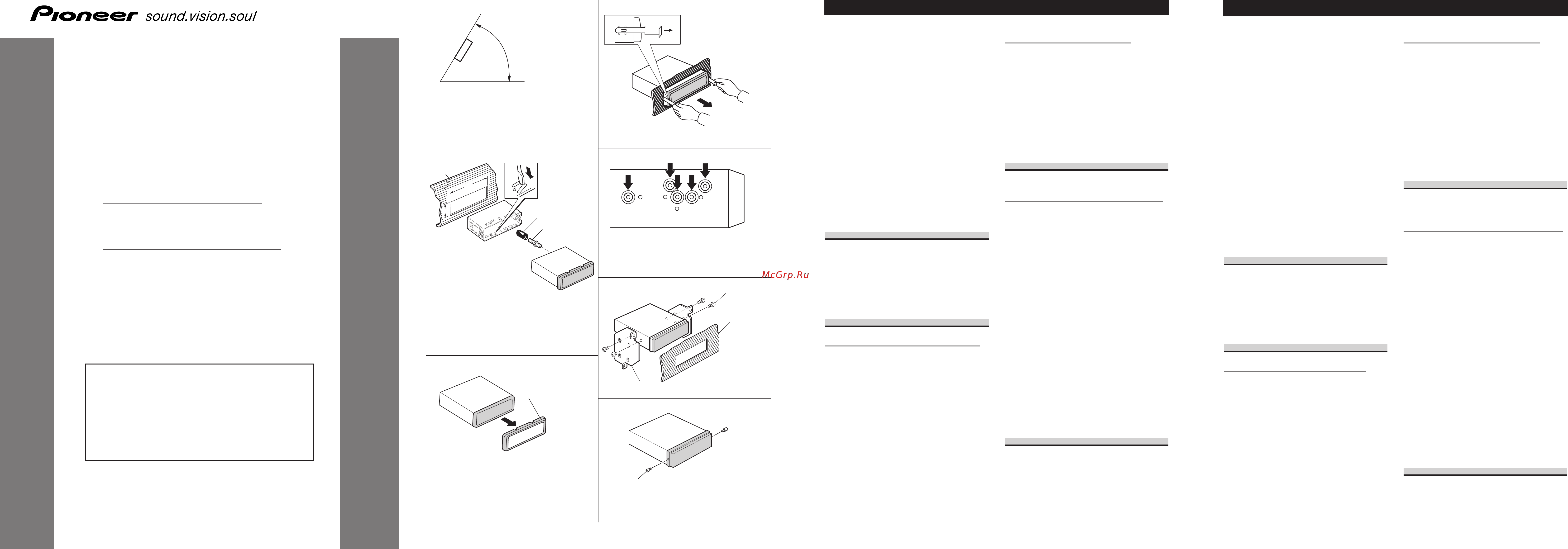
• Si el ángulo de la instalación excede los 60° del
lado horizontal, la unidad podría no brindar su
óptimo funcionamiento. (Fig. 1)
Montaje delantero/trasero DIN
Esta unidad quede instalarse correstamente de la
“Delantera” (montaje delantero DIN convenciona)
o “Trasera” (montaje trasero DIN, utilizando los
tornillos roscados en los constados del chasis de
la unidad). Para detalles, refiérase a los métodos
de instalación ilustrados abajo.
Montaje delantero DIN
Instalación con tope de goma (Fig. 2)
1. Tablero de instrumentos
2. Soporte
Después de insertar el soporte en la tabla de
mandos, luego seleccione las orejetas apropiadas
según el grosor del material de la tabla de man-
dos y dóblelos.
(Instale lo más firme posible usando las lengüe-
tas superior e inferior. Para fijar, doble las
lengüetas 90 grados.)
3. Tope de goma
4. Tornillo
Quitado de la unidad (Fig. 3) (Fig. 4)
5. Marco
Para extraer marco, extienda las partes superior e
inferior del marco hacia fuera para soltarlo. (Para
la fijación del marco, apunte el lado con ranura
hacia abajo.)
• Suelte el painel delantero para facilitar la
extracción del marco.
6. Inserte las herramientas de extracción suminis-
tradas en la unidad, como se indica en la figura,
hasta que se enganchen en su positión.
Tire de la unidad mientras mantiene las her-
ramientas presionadas contra los lados de la
unidad.
Montaje trasero DIN
Instalación usando los agujeros para
tornillos ubicados en ambos costados de
la unidad (Fig. 3) (Fig. 5) (Fig. 6)
1. Quite el marco.
5. Marco
Para extraer marco, extienda las partes superior e
inferior del marco hacia fuera para soltarlo. (Para
la fijación del marco, apunte el lado con ranura
hacia abajo.)
• Suelte el painel delantero para facilitar la
extracción del marco.
2. Fijación de la unidad a la ménsula
de montaje existente.
7. Seleccione una posición en la que los orificios
para los tornillos del soporte y del de la unidad
principal queden alineados, y apriete los tornillos
en 2 lugares de un lado. Utilice ya sea los tornil-
los de fijación (5 × 8 mm) o los tornillos a paño
(5 × 9 mm), dependiendo de la forma de los ori-
ficios de tornillo en la ménsula.
8. Tornillo
9. Ménsula de montaje de radio existente
10. Tablero de instrumentos o consola
Sobre los tornillos de fijación del
panel delantero (Fig. 7)
11. Tornillos de fijación
Si no desea utilizar la función de extracción y
colocación del panel delantero, utilice los tornil-
los de fijación suministrados y fije el panel
delantero a esta unidad.
Instalación <ESPAÑOL>
Note:
• Before making a final installation of the unit,
temporarily connect the wiring to confirm that
the connections are correct and the system works
properly.
• Use only the parts included with the unit to
ensure proper installation. The use of unautho-
rized parts can cause malfunctions.
• Consult with your nearest dealer if installation
requires the drilling of holes or other modifica-
tions of the vehicle.
• Install the unit where it does not get in the dri-
ver’s way and cannot injure the passenger if there
is a sudden stop, like an emergency stop.
• The semiconductor laser will be damaged if it
overheats, so don’t install the unit anywhere hot
— for instance, near a heater outlet.
• If installation angle exceeds 60° from horizontal,
the unit might not give its optimum performance.
(Fig. 1)
DIN Front/Rear-mount
This unit can be properly installed either from
“Front” (conventional DIN Front-mount) or
“Rear” (DIN Rear-mount installation, utilizing
threaded screw holes at the sides of unit chassis).
For details, refer to the following illustrated
installation methods.
DIN Front-mount
Installation with the rubber bush (Fig. 2)
1. Dashboard
2. Holder
After inserting the holder into the dashboard,
then select the appropriate tabs according to the
thickness of the dashboard material and bend
them.
(Install as firmly as possible using the top and
bottom tabs. To secure, bend the tabs 90
degrees.)
3. Rubber bush
4. Screw
Removing the Unit (Fig. 3) (Fig. 4)
5. Frame
To remove the frame, extend top and bottom of
the frame outwards in order to unlock it. (When
reattaching the frame, point the side with a
groove downwards and attach it.)
• It becomes easy to remove the frame if the front
panel is released.
6. Insert the supplied extraction keys into the unit,
as shown in the figure, until they click into place.
Keeping the keys pressed against the sides of the
unit, pull the unit out.
DIN Rear-mount
Installation using the screw holes on the
side of the unit (Fig. 3) (Fig. 5) (Fig. 6)
1. Remove the frame.
5. Frame
To remove the frame, extend top and bottom of
the frame outwards in order to unlock it. (When
reattaching the frame, point the side with a
groove downwards and attach it.)
• It becomes easy to remove the frame if the front
panel is released.
2. Fastening the unit to the factory
radio mounting bracket.
7. Select a position where the screw holes of the
bracket and the screw holes of the head unit
become aligned (are fitted), and tighten the
screws at 2 places on each side. Use either truss
screws (5 × 8 mm) or flush surface screws
(5 × 9 mm), depending on the shape of the screw
holes in the bracket.
8. Screw
9. Factory radio mounting bracket
10. Dashboard or Console
About the fixing screws for the
front panel (Fig. 7)
11. Fixing screw
If you do not operate the Removing and
Attaching the Front Panel Function, use the sup-
plied fixing screws and fix the front panel to this
unit.
Installation <ENGLISH>
INSTALLATION MANUAL
MANUEL D’INSTALLATION
<KMMNX> <04G00000>
DEH-2700R
DEH-2700RB
Printed in China
Imprimé en Chine
<YRD5015-A/U> EW
This product conforms to new cord colors.
Los colores de los cables de este producto se confor-
man con un nuevo código de colores.
Dieses Produkt entspricht den neuen Kabelfarben.
Le code de couleur des câbles utilisé pour ce produit
est nouveau.
Questo prodotto è conforme ai nuovi codici colori.
De kleuren van de snoeren van dit toestel zijn gewijzigd.
60°
5
Fig. 2
Abb. 2
Afb. 2
53
182
1
2
3
4
6
8
10
9
7
11
Fig. 1
Abb. 1
Afb. 1
Fig. 3
Abb. 3
Afb. 3
Fig. 4
Abb. 4
Afb. 4
Fig. 5
Abb. 5
Afb. 5
Fig. 6
Abb. 6
Afb. 6
Fig. 7
Abb. 7
Afb. 7
YRD5015AU 6/28/04 16:01 Page 1
Содержание
- About the fixing screws for the front panel fig 7 1
- Deh 2700r deh 2700rb 1
- Din front mount 1
- Din front rear mount 1
- Din rear mount 1
- Installation manual 1
- Manuel d installation 1
- Montaje delantero din 1
- Montaje delantero trasero din 1
- Montaje trasero din 1
- Sobre los tornillos de fijación del panel delantero fig 7 1
- Anbringen dieser einheit an die werks radiomontagehalterung 2
- Assicurare l unità alla staffa di montaggio radio 2
- Befestigungsschrauben für die frontplatte abb 7 2
- Bevestigen van het apparaat aan de radio bevestigingsbeugel van de fab rikant 2
- Din achterbevestiging 2
- Din befestigung von vorne hinten 2
- Din rückmontage 2
- Din voor achterbevestiging 2
- Din voorbevestiging 2
- Din vordermontage 2
- Dépose de l unite fig 3 fig 4 2
- Einbau mit der gummibuchse abb 2 2
- Enlever le cadre 2
- Entnahme des gerätes abb 3 abb 4 2
- Estrazione dell unità fig 3 fig 4 2
- Fixation de l appareil au support pour le montage de la radio installée par le constructeur 2
- Installatie met de rubber mof afb 2 2
- Installatie via de schroefgaten in de zijkant van het apparaat afb 3 afb 5 afb 6 2
- Installation avec une bague en caoutchouc fig 2 2
- Installation en utilisant les trous de vis sur les côtés de l appareil fig 3 fig 5 fig 6 2
- Installation unter gebrauch der gewindebohrungen an der seite der einheit abb 3 abb 5 abb 6 2
- Installazione con la boccola di gomma fig 2 2
- Installazione per mezzo dei fori per vite situati sui lati dell unità fig 3 fig 5 fig 6 2
- Meer over de bevestigingsschroeven voor het voorpaneel afb 7 2
- Montage din arrière 2
- Montage din avant 2
- Montage din avant arrière 2
- Montaggio din forntale posteriore 2
- Montaggio din frontale 2
- Montaggio din posteriore 2
- Nehmen sie den rahmen ab 2
- Rimuovere il telaio 2
- Verwijder het frame 2
- Verwijderen van het apparaat afb 3 afb 4 2
- Viti di fissaggio per il pannello anteriore fig 7 2
- À propos des vis de fixation de la face avant fig 7 2
- Connecting the units 3
- Connection diagram fig 8 3
- Fig 8 abb 8 afb 8 3
- Conexión de las unidades 4
- Connecting the units 4
- Diagrama de conexión fig 8 4
- Fig 8 abb 8 afb 8 4
- Anschließen der geräte 5
- Connexion des appareils 5
- Hinweis 5
- Remarque 5
- Schéma de connexion 5
- Verbindungs diagramm abb 8 5
- Aansluiten van de apparatuur 6
- Aansluitschema afb 8 6
- Acc stand 6
- Cavi diffusore bianco anteriore sinistro bianco nero anteriore sinistro grigio anteriore destro grigio nero anteriore destro verde posteriore sinistro verde nero posteriore sinistro violetto posteriore destro violetto nero posteriore destro 17 cavi di collegamento con spine a terminale rca venduto separatamente 18 amplificatore venduto separatamente 19 blu bianco al terminale di comando del sistema dell amplificatore di potenza massimo 300 ma con corrente continua a 12 v 20 comando a distanza del sistema 21 blu bianco 7 al terminale di controllo del relè dell antenna ad alzo automatico massimo 300 ma con corrente continua a 12 v 22 blu bianco 6 23 la posizione dei poli del connettore iso differisce in relazione al tipo di veicolo se il polo 5 è del tipo per il comando dell antenna collegare 6 e 7 nei veicoli di altri tipi non collegare mai 6 e 7 24 sinistra 25 destra 26 diffusore posteriore 27 eseguire questi collegamenti nel caso in cui si faccia uso di un amplificatore opzionale 6
- Collegamento degli apparecchio 6
- Geen acc stand 6
- Luidsprekerdraden wit linksvoor wit zwart linksvoor grijs rechtsvoor grijs zwart rechtsvoor groen linksachter groen zwart linksachter paars rechtsachter paars zwart rechtsachter 17 aansluitsnoeren met rca stekkers los verkrijgbaar 18 eindversterker los verkrijgbaar 19 blauw wit naar de systeembedieningsaansluiting van de eindversterker max 300 ma 12 volt gelijkstroom 20 systeem afstandsbediening 21 blauw wit 7 naar auto antenne relaisbedieningsaansluiting max 300 ma 12 volt gelijkstroom 22 blauw wit 6 23 de penposities van de iso stekker kunnen verschillen afhankelijk van het soort voortuig sluit 6 en 7 aan wanneer pen 5 van het antenne bedieningstype is in andersoortige voortuigen mag u 6 en 7 nooit aansluiten 24 links 25 rechts 26 achter luidspreker 27 maak deze verbindingen wanneer u de los verkri jgbare versterker gebruikt 6
- Opmerking 6
- Posizione acc assente 6
- Posizione acc presente 6
- Schema di collegamento fig 8 6
- Snoeren voor dit product en overeenkomende snoeren voor andere producten hebbern mogelijk verschillende kleuren ookal is de functie van de snoeren hetzelfde zie voor het verbinden van dit product met een ander product daarom de handleiding van beide producten en verbind de snoeren met dezelfde functie met elkaar 6
- Uitgang achter 2 dit product 3 antenne aansluiting 4 zekering 5 aansluiting voor de afstandsbediening met draad lees de handleiding van de afstandsbediening met draad los verkrijgbaar 6 opmerking de functie van 3 en 5 is mogelijk versc hillend afhankelijk van het type auto indien dit het geval is moet u 2 met 5 en 4 met 3 verbinden 7 verbind de draden van dezelfde kleur met elkaar 8 dopje 1 niet verwijderen indien u deze aansluiting niet gebruikt 9 geel 3 ondersteuning of accessoire 10 geel 2 naar de aansluiting die altijd van stroom voorzien wordt onafhankelijk van de stand van het kontact 11 rood 5 accessoire of ondersteuning 12 rood 4 naar de door het kontact 12 volt gelijkstroom on off geregelde elektrische aansluiting 13 zwart aarde naar de metalen carrosserie van het voertuig 14 iso aansluiting opmerking in bepaalde auto s is de iso aansluiting mogelijk in tweeën verdeeld u moet in dat geval een verbinding met beide aansluitingen maken 15 geel zwart als u apparatuur gebruikt die 6
- Uscita posteriore 2 questo apparecchio 3 terminal per antenna 4 fusibile 5 connettore del telecomando a filo per l utilizzo del telecomando a filo venduto separatamente vedere le istruzioni riportate nel relativo manuale di istruzioni 6 nota a seconda del tipo di veicolo la funzione di 3 e 5 potrebbe essere differente in tal caso collegare sempre 2 a 5 e 4 a 3 7 collegare fra loro cavi di uguale colore 8 cappuccio 1 se questo terminale non è in uso non togliere il cappuccio 9 giallo 3 riserva o accessoria 10 giallo 2 al terminale constantemente alimentato qualunque sia la posizione della chiave d accensione 11 rosso 5 accessoria o riserva 12 rosso 4 collegare alla chiave d avviamento on off con corrente continua a 12 v 13 nero massa al telaio parte metallica dell automobile 14 connettore iso nota in alcuni veicoli il connettore iso potrebbe essere diviso in due in tal caso non mancare di connettere ambedue i connettori 15 giallo nero in caso di utilizzo di un apparecchio provvisto dell 6
- Yrd5015au 6 28 04 16 01 page 21 6
Похожие устройства
- CARLIEUKLIMA EUCERAMIC INDUSTRY HE 18/10 Инструкция по эксплуатации
- Pioneer DEH-2700RB Руководство по установке
- Pioneer DEH-2700RB Руководство пользователя
- CARLIEUKLIMA EUCERAMIC INDUSTRY HE 22/12 Инструкция по эксплуатации
- CARLIEUKLIMA EUCERAMIC INDUSTRY HE 29/16 Инструкция по эксплуатации
- CARLIEUKLIMA EUCERAMIC INDUSTRY HE 44/12+12V1 Инструкция по эксплуатации
- Pioneer DEH-2800MP Руководство пользователя
- Pioneer DEH-2800MP Руководство по установке
- CARLIEUKLIMA EUCERAMIC INDUSTRY HE 58/16+16V1 Инструкция по эксплуатации
- Pioneer DEH-2800MPB Руководство по установке
- CARLIEUKLIMA EUCERAMIC INDUSTRY HE 7/4 Инструкция по эксплуатации
- Pioneer DEH-2820MP Руководство по установке
- Pioneer DEH-2900MP Руководство по установке
- Pioneer DEH-2910MP Руководство по установке
- Pioneer DEH-2920MP Руководство по установке
- Pioneer DEH-2920MP Руководство пользователя
- Pioneer DEH-3000MP Руководство по установке
- Pioneer DEH-3000MP Руководство пользователя
- Pioneer DEH-30MP Руководство по установке
- Pioneer DEH-3200UB Приложение
Скачать
Случайные обсуждения