
Pioneer DEH-P6000UB Руководство по установке онлайн
INSTALLATION MANUAL
MANUEL D’INSTALLATION
DEH-P6000UB
<KSNNX> <07I00000>
Printed in Thailand
Imprimé en Thaïlande
<QRD3005-A/N> EW
Installation English Installation English Instalación Español
Note
• Check all connections and systems before final
installation.
• Do not use unauthorized parts. The use of
unauthorized parts may cause malfunctions.
• Consult with your dealer if installation requires
drilling of holes or other modifications of the
vehicle.
• Do not install this unit where:
— it may interfere with operation of the vehicle.
— it may cause injury to a passenger as a result
of a sudden stop.
• The semiconductor laser will be damaged if it
overheats. Install this unit away from hot places
such as near the heater outlet.
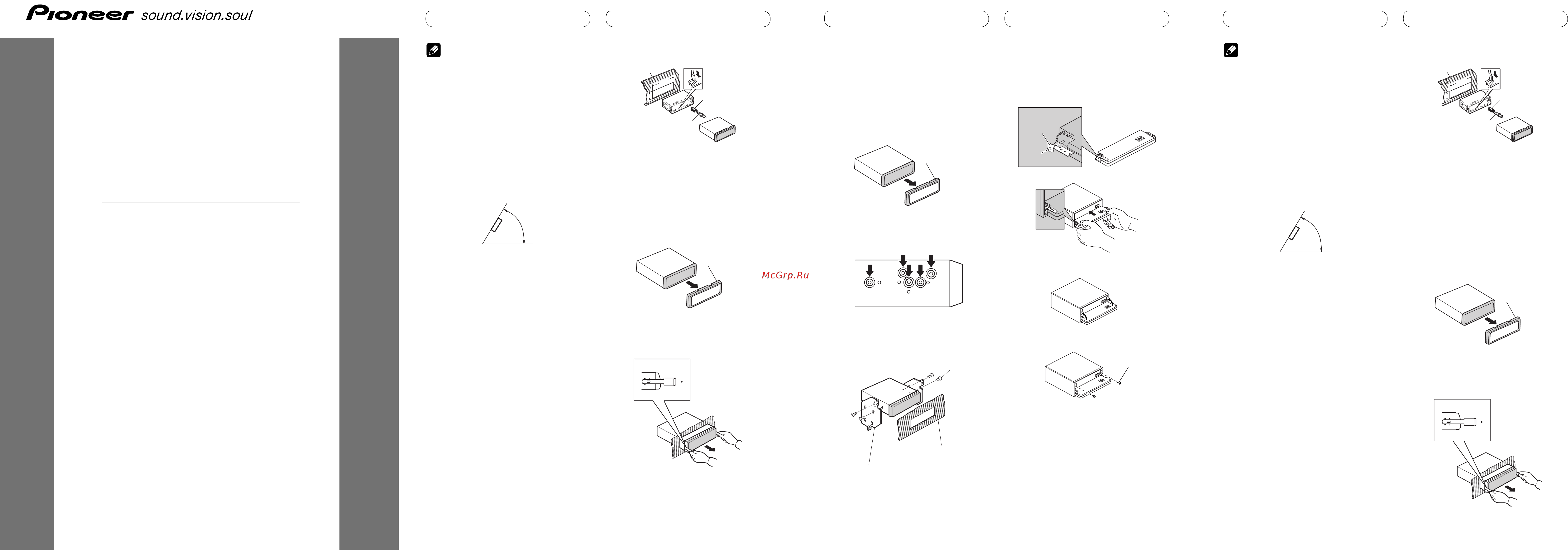
• Optimum performance is obtained when the unit is
installed at an angle of less than 60°.
60°
DIN Front/Rear-mount
This unit can be properly installed either from
"Front" (conventional DIN Front-mount) or
"Rear" (DIN Rear-mount installation, utilizing
threaded screw holes at the sides of unit
chassis). For details, refer to the following
installation methods.
DIN Front-mount
Installation with the rubber bush
1. Insert the mounting sleeve into the
dashboard.
• When installing in a shallow space, use a
supplied mounting sleeve. If there is enough
space behind the unit, use factory supplied
mounting sleeve.
2. Secure the mounting sleeve by using
a screwdriver to bend the metal tabs
(90°) into place.
3. Install the unit as illustrated.
53
53
1
1
182182
Removing the Unit
1.
Extend top and bottom of the trim
ring outwards to remove the trim
ring. When reattaching the trim ring,
push the trim ring onto the unit until
it clicks. (If the trim ring is attached
upside down, the trim ring will not fit
properly.)
• It becomes easy to remove the trim ring if the
front panel is released.
2. Insert the supplied extraction keys
into both sides of the unit until they
click into place.
3. Pull the unit out of the dashboard.
DIN Rear-mount
1.
Extend top and bottom of the trim
ring outwards to remove the trim
ring. When reattaching the trim ring,
push the trim ring onto the unit until
it clicks. (If the trim ring is attached
upside down, the trim ring will not fit
properly.)
• It becomes easy to remove the trim ring if the
front panel is released.
2. Determine the appropriate position
where the holes on the bracket and
the side of the unit match.
3. Tighten two screws on each side.
• Use either truss screws (5 mm × 8 mm)
or flush surface screws (5 mm × 9 mm),
depending on the shape of screw holes in the
bracket.
Fastening the front panel
If you do not plan to detach the front panel,
the front panel can be fastened with supplied
screws and holders.
1. Attach the holders to both sides of the
front panel.
2. Replace the front panel to the unit.
3. Flip the holders into upright
positions.
4. Fix the front panel to the unit using
screws.
Nota
• Verifique todas las conexiones y sistemas antes de
la instalación final.
• No utilice piezas no autorizadas. El uso de piezas
no autorizadas puede causar un fallo de
funcionamiento.
• Consulte su revendedor si se requiere taladrar
agujeros o hacer otras modificaciones del
vehículo para la instalación.
• No instale esta unidad donde:
— pueda interferir con la operación del vehículo.
— pueda causar lesiones a un pasajero en el caso
de una parada brusca.
• El láser semiconductor se dañará si se
sobrecalienta. Instale esta unidad alejada de
lugares calientes como cerca de la salida del
calentador.
• Se obtiene el rendimiento óptimo cuando se instala
la unidad en un ángulo inferior a 60°.
60°
Montaje delantero/trasero
DIN
Se puede instalar esta unidad apropiadamente
mediante el montaje “delantero” (montaje
delantero DIN convencional) o montaje
“trasero” (montaje trasero DIN utilizando
los agujeros de tornillo roscados en los lados
del bastidor de la unidad). Para los detalles,
consulte los siguientes métodos de instalación.
Montaje delantero DIN
Instalación con el buje de caucho
1. Inserte el manguito de montaje en el
tablero de instrumentos.
• Cuando instale en un lugar poco profundo,
uti
lice el manguito de montaje suministrado. Si
hay espacio suficiente detrás de la unidad, utilice
el manguito de montaje suministrado de fábrica.
2. Fije el manguito de montaje
utilizando un destornillador para
doblar las lengüetas de metal (90°) en
posición.
3. Instale la unidad como se muestra.
53
53
1
1
182182
Extracción de la unidad
1. Extienda las partes superior e
inferior del anillo de compensación
hacia fuera para extraer el anillo de
compensación. Cuando reinstale
el anillo de compensación, empuje
el anillo de compensación en la
unidad hasta que encaje con un
“clic”. (Si se instala el anillo de
compensación invertido, puede que
el anillo de compensación no se
encaj
e correctamente.)
• Se hace más fácil quitar el anillo de
compensación si se suelta el panel delantero.
2. Inserte las llaves de extracción
suministradas en ambos lados de la
unidad hasta que se enganchen en
posición.
3. Tire de la unidad del tablero de
instrumentos.
Dashboard
Mounting sleeve
Rubber bush
Screw
Trim ring
Trim ring
Dashboard or Console
Factory radio mounting bracket
Screw
Screw
Holder
Tablero de
instrumentos
Manguito de montaje
Buje de caucho
Tornillo
Anillo de
compensación
Содержание
- Attach the holders to both sides of the front panel 1
- Deh p6000ub 1
- Determine the appropriate position where the holes on the bracket and the side of the unit match 1
- Din front rear mount 1
- Extend top and bottom of the trim ring outwards to remove the trim ring when reattaching the trim ring push the trim ring onto the unit until it clicks if the trim ring is attached upside down the trim ring will not fit properly 1
- Fastening the front panel 1
- Fije el manguito de montaje utilizando un destornillador para doblar las lengüetas de metal 90 en posición 1
- Fix the front panel to the unit using screws 1
- Flip the holders into upright positions 1
- If you do not plan to detach the front panel the front panel can be fastened with supplied screws and holders 1
- Insert the mounting sleeve into the dashboard 1
- Insert the supplied extraction keys into both sides of the unit until they click into place 1
- Inserte el manguito de montaje en el tablero de instrumentos 1
- Inserte las llaves de extracción suministradas en ambos lados de la unidad hasta que se enganchen en posición 1
- Instale la unidad como se muestra 1
- Install the unit as illustrated 1
- Installation english installation english instalación español 1
- Installation manual 1
- Manuel d installation 1
- Montaje delantero trasero din 1
- Pull the unit out of the dashboard 1
- Replace the front panel to the unit 1
- Se puede instalar esta unidad apropiadamente mediante el montaje delantero montaje delantero din convencional o montaje trasero montaje trasero din utilizando los agujeros de tornillo roscados en los lados del bastidor de la unidad para los detalles consulte los siguientes métodos de instalación 1
- Secure the mounting sleeve by using a screwdriver to bend the metal tabs 90 into place 1
- This unit can be properly installed either from front conventional din front mount or rear din rear mount installation utilizing threaded screw holes at the sides of unit chassis for details refer to the following installation methods 1
- Tighten two screws on each side 1
- Tire de la unidad del tablero de instrumentos 1
- Ausbauen des geräts 2
- Befestigung der frontplatte 2
- Din einbau an der rückseite 2
- Din einbau an der vorderseite 2
- Din einbau an der vorderseite rückseite 2
- Einbau mit der gummibuchse 2
- Fijación del panel delantero 2
- Installation avec l amortisseur en caoutchouc 2
- Installation français einbau deutsch einbau deutsch instalación español 2
- Montage avant arrière din 2
- Montage avant din 2
- Montaje trasero din 2
- Retrait de l appareil 2
- Din voor achter montage 3
- Din voor montage 3
- Fissaggio del pannello anteriore 3
- Fixation du panneau avant 3
- Installatie met het rubber tussenstuk 3
- Installation français installazione italiano installazione italiano installatie nederlands 3
- Installazione con la guaina di gomma 3
- Installazione din frontale 3
- Installazione din frontale posteriore 3
- Installazione din posteriore 3
- Montage arrière din 3
- Rimozione dell unità 3
- Verwijderen van het toestel 3
- Din achter montage 4
- Installatie nederlands установка pycckий установка pycckий 4
- Vastzetten van het voorpaneel 4
- Заднее крепление по стандарту din 4
- Закрепление передней панели 4
- Переднее заднее крепление по стандарту din 4
- Переднее крепление по стандарту din 4
- Connecting the units english connecting the units english 5
- Connection diagram 5
- Anschließen der geräte 6
- Anschlussdiagramm 6
- Conexión de las unidades 6
- Deutsch 6
- Diagrama de conexión 6
- Español 6
- Collegamento delle unità 7
- Connexions des appareils 7
- Diagramme de connexion 7
- Français 7
- Italiano 7
- Schema di collegamento 7
- Aansluiten van de toestellen 8
- Aansluitingsschema 8
- Nederlands 8
- Pycckий 8
- Подключение устройств 8
Похожие устройства
- Pioneer DEH-P6300R Руководство по установке
- Pioneer DEH-P6400R Руководство по установке
- Pioneer DEH-P6400R Руководство пользователя
- Pioneer DEH-P6500R Руководство по установке
- Pioneer DEH-P6500R Руководство пользователя
- Pioneer DEH-P65BT Руководство пользователя
- Pioneer DEH-P65BT Руководство по установке
- Pioneer DEH-P6600R Руководство пользователя
- Pioneer DEH-P6700MP Руководство по установке
- Pioneer DEH-P6800MP Руководство по установке
- Pioneer DEH-P6800MP Руководство пользователя
- Pioneer DEH-P6900IB Руководство пользователя
- Pioneer DEH-P6900IB Руководство по установке
- Pioneer DEH-P7000UB Краткое руководство
- Pioneer DEH-P7000UB Руководство по установке
- Pioneer DEH-P700BT Руководство по установке
- Pioneer DEH-P700BT Краткое руководство
- Pioneer DEH-P700BT Руководство пользователя
- Pioneer DEH-P70BT Руководство по установке
- Pioneer DEH-P70BT Руководство пользователя
Скачать
Случайные обсуждения