
Pioneer AVH-P5000DVD Инструкция по установке онлайн
Содержание
- Avh p5000dvd 1
- Connecting the units english 1
- Sound vis ion sou 1
- Connecting the units english 2
- Caution 3
- Connecting the units english 3
- Before installing the unit 4
- Brackets 4
- Decide the position of the side 4
- Determine the appropriate posi 4
- Din front mount 4
- Din front rear mount 4
- Din rear mount 4
- Fastening the front panel 4
- Fix the front panel to the unit 4
- Install the unit into the dash 4
- Installation english 4
- Mounting sleeve 4
- Remove the trim ring and the 4
- Tighten two screws on each side 4
- Tion where the holes on the bracket and the side of the unit match 4
- Using screws and holder after removing the trim ring 4
- Подключение устройств русский 5
- Поставляемые детали 5
- Подключение устройств русский 6
- Соединительный шнур питания соединение с усилителем мощности который продается отдельно 6
- Использование дисплея подключенного к видео выходу 7
- Монтаж соединительной коробки оптического кабеля 7
- Подключение внешнего видео компонента и дисплея 7
- Подключение камеры заднего обзора 7
- Подключение многоканального процессора 7
- Подключение устройств русский 7
- Подсоединение и монтаж соединительной коробки оптического кабеля 7
- Предупреждение 7
- Соединение оптического кабеля 7
- Выберите положение боковых 8
- Заднее крепление din 8
- Закрепите переднюю панель с 8
- Закрепление передней панели 8
- Затяните по два винта на 8
- Каждой стороне 8
- Кронштейнов 8
- Монтажный рукав 8
- Определите подходящее 8
- Перед установкой устройства 8
- Переднее заднее крепление din 8
- Переднее крепление din 8
- Положение когда отверстия на кронштейне и боковой стороне устройства совпадают 8
- Приборной панели 8
- Примечания 8
- Удалите декоративное кольцо и 8
- Установка русский 8
- Установка устройства в 8
- Устройством используя винты и держатель после удаления декоративного кольца 8
Похожие устройства
- CITEL DAC50VG-10-150 Инструкция по установке
- CITEL DAC50VG-10-275 Инструкция по установке
- CITEL DAC50VG-10-320 Инструкция по установке
- CITEL DAC50VG-11-150 Инструкция по установке
- CITEL DAC50VG-11-275 Инструкция по установке
- CITEL DAC50VG-11-320 Инструкция по установке
- CITEL DAC50VG-20-150 Инструкция по установке
- CITEL DAC50VG-20-275 Инструкция по установке
- CITEL DAC50VG-20-320 Инструкция по установке
- CITEL DAC50VG-30-150 Инструкция по установке
- CITEL DAC50VG-30-275 Инструкция по установке
- CITEL DAC50VG-30-320 Инструкция по установке
- CITEL DAC50VG-31-150 Инструкция по установке
- CITEL DAC50VG-31-275 Инструкция по установке
- CITEL DAC50VG-31-320 Инструкция по установке
- CITEL DAC50VG-40-150 Инструкция по установке
- CITEL DAC50VG-40-275 Инструкция по установке
- CITEL DAC50VG-40-320 Инструкция по установке
- CITEL DS72R-120 Инструкция по установке
- CITEL DS72R-120/G Инструкция по установке
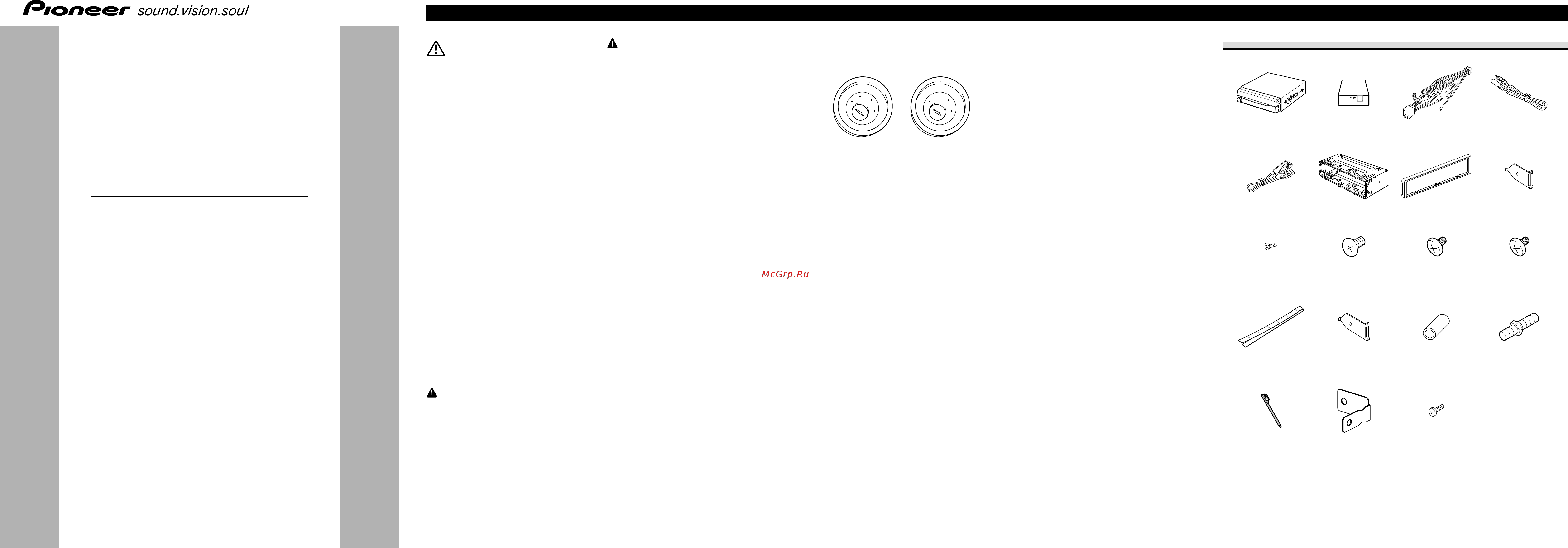
sound vis ion sou Connecting the Units ENGLISH A WARNING CAUTION PIONEER does not recommend that you install or service your display yourself Installing or servicing the product may expose you to risk of electric shock or other hazards Refer all installation and servicing of your display to authorized Pioneer service personnel Secure all wiring with cable clamps or electrical tape Do not allow any bare wiring to remain exposed AVH P5000DVD Do not drill a hole into the engine com partment to connect the yellow lead of the unit to the vehicle battery Engine vibration may eventually cause the insu lation to fail at the point where the wire passes from the passenger compartment into the engine compartment Take extra care in securing the wire at this point It is extremely dangerous to allow the display lead to become w ound around the steering column or gearshift Be sure to install the display in such a way that it will not obstruct driving Make sure that w ires will not interfere with moving parts of the vehicle such as the gearshift parking brake or seat slid ing mechanism Do not shorten any leads If you do the protection circuit may fail to work prop erly WARNING LIGHT GREEN LEAD AT POWER CONNEC TOR IS DESIGNED TO DETECT PARKED STATUS AND MUST BE CONNECTED TO THE POWER SUPPLY SIDE OF THE PARK ING BRAKE SWITCH IMPROPER CONNEC TION OR USE OF THIS LEAD MAY VIOLATE APPLICABLE LAW AND MAY RESULT IN SERIOUS INJURY OR DAMAGE Printed in Thailand Напечатано в Таиланде CRD4274 A N RE KMINX 07K00000 To avoid the risk of accident and the potential vio lation of applicable laws the front DVD or TV sold separately feature should never be used while the vehicle is being driven Also Rear Displays should not be in a location where it is a visible distraction to the driver In some countries or states the viewing of images on a display inside a vehicle even by persons other than the driver may be illegal Where such regulations apply they must be obeyed and this unit s DVD features should not be used Note This unit cannot be installed in a vehicle with out ACC accessory position on the ignition switch ACC position No ACC position Use this unit in other than the following condi tions could result in fire or malfunction Vehicles with a 12 volt battery and negative grounding Speakers with 50 W output value and 4 ohm to 8 ohm impedance value To prevent short circuit overheating or malfunc tion be sure to follow the directions below Disconnect the negative terminal of the battery before installation Secure the wiring with cable clamps or adhe sive tape To protect the wiring wrap adhesive tape around them where they lie against metal parts Place all cables away from moving parts such as gear shift and seat rails Place all cables away from hot places such as near the heater outlet Do not pass the yellow cable through a hole into the engine compartment to connect to a battery Cover any disconnected cable connectors with insulating tape Do not remove RCA caps if RCA cables are not used Do not shorten any cables Control signal is output through blue white cable when this unit is powered on Connect it to an external power amp s system remote control or the vehicle s auto antenna relay control terminal max 300 mA 12 V DC If the vehicle is equipped with a glass antenna connect it to the antenna booster power supply terminal Never connect blue white cable to external power amp s power terminal Also never connect it to the power terminal of the auto antenna Otherwise battery drain or malfunction may result Parts supplied This product Tuner box Power cord Black cable is ground This cable and other prod uct s ground cable especially high current prod ucts such as power amp must be wired separate ly Otherwise fire or malfunction may result if they are accidentally detached USB cable Screw 2 mm x 3 mm 4 pcs pre installed Concealing tape Mounting sleeve Trim ring Side bracket small pre installed pre installed 2 pcs pre installed Rush surface screw 5 nun x 6 nun 6 pcs Binding screw 5 mm x 6 mm Binding screw 4 mm x 3 mm 2 are pre installed 4 pcs 4 pcs Side bracket large 2 pcs Rubber bush Never cut the insulation of the power cable of this unit in order to share the power to other equipment Current capacity of the cable is limited Use a fuse of the rating prescribed Never wire the speaker negative cable directly to ground Never band together multiple speaker s nega tive cables Antenna cable IP BUS connectors are color coded Be sure to connect connectors of the same color Touch panel pen Holder Screw 2 mm x 5 mm 2 pcs Double ended screw