
Pioneer DEH-2800 MP Инструкция по установке онлайн
Nota:
• Antes de finalmente instalar la unidad, conecte el
cableado temporalmente y compruebe que las
conexiones están correctas e que el sistema fun-
ciona debidamente.
• Utilice sólo las piezas que se incluyen con esta
unidad para asegurar la instalación adecuada. El
uso de piezas no autorizadas podría causar fallos
de funcionamiento.
• Consulte con su distribuidor si la instalación
requiere del taladro de orificios u otras modifica-
ciones del vehículo.
• Instale la unidad donde no alcance el espacio del
conductor, y donde no pueda dañar a los
pasajeros si sucediera un paro repentino, como
una detención de emergencia.
• El semiconductor láser se dañará si se sobre-
calienta, por eso no instale la unidad en un lugar
caliente – por ejemplo, cerca de la salida de un
calefactor.
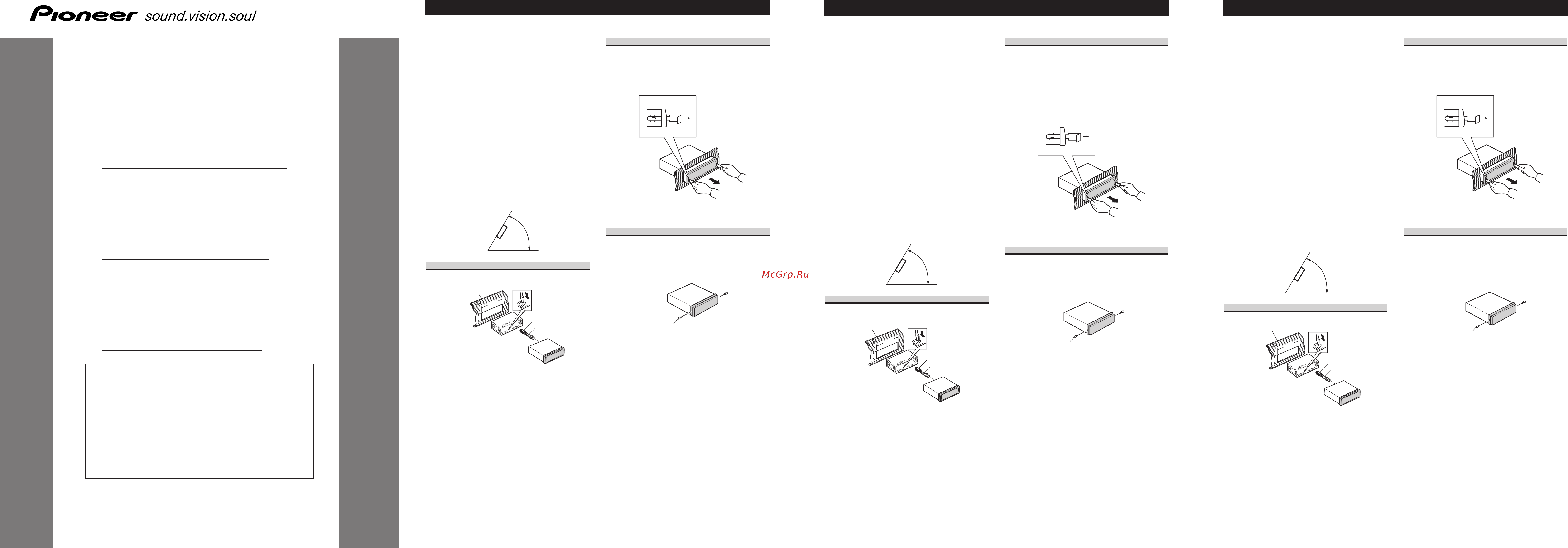
• Si el ángulo de la instalación excede los 60° del
lado horizontal, la unidad podría no brindar su
óptimo funcionamiento.
Instalación con tope de goma
Después de insertar el soporte en la tabla de
mandos, luego seleccione las orejetas apropiadas
según el grosor del material de la tabla de man-
dos y dóblelos.
(Instale lo más firme posible usando las lengüe-
tas superior e inferior. Para fijar, doble las
lengüetas 90 grados.)
Quitado de la unidad
Inserte las herramientas de extracción suminis-
tradas en la unidad, como se indica en la figura,
hasta que se enganchen en su positión.
Tire de la unidad mientras mantiene las her-
ramientas presionadas contra los lados de la
unidad.
Sobre los tornillos de fijación del
panel delantero
Si no desea utilizar la función de extracción y
colocación del panel delantero, utilice los tornil-
los de fijación suministrados y fije el panel
delantero a esta unidad.
Tornillos de fi
j
ació
n
53
53
1
1
182182
So
p
ort
e
To
p
e de
g
om
a
T
o
rnill
o
Tabler
o
de
instrument
o
s
60°
Instalación <ESPAÑOL>
Note:
• Before making a final installation of the unit,
temporarily connect the wiring to confirm that
the connections are correct and the system works
properly.
• Use only the parts included with the unit to
ensure proper installation. The use of unautho-
rized parts can cause malfunctions.
• Consult with your nearest dealer if installation
requires the drilling of holes or other modifica-
tions of the vehicle.
• Install the unit where it does not get in the dri-
ver’s way and cannot injure the passenger if there
is a sudden stop, like an emergency stop.
• The semiconductor laser will be damaged if it
overheats, so don’t install the unit anywhere hot
— for instance, near a heater outlet.
• If installation angle exceeds 60° from horizontal,
the unit might not give its optimum performance.
Installation with the rubber bush
After inserting the holder into the dashboard,
then select the appropriate tabs according to the
thickness of the dashboard material and bend
them.
(Install as firmly as possible using the top and
bottom tabs. To secure, bend the tabs 90
degrees.)
Removing the Unit
Insert the supplied extraction keys into the unit,
as shown in the figure, until they click into place.
Keeping the keys pressed against the sides of the
unit, pull the unit out.
About the fixing screws for the
front panel
If you do not operate the Removing and
Attaching the Front Panel Function, use the sup-
plied fixing screws and fix the front panel to this
unit.
Fixing screw
53
53
1
1
182182
H
o
lde
r
D
ashb
o
ar
d
R
ubb
e
r bus
h
S
cre
w
60°
Installation <ENGLISH>
INSTALLATION MANUAL
MANUEL D’INSTALLATION
<KSNNX> <05K00000>
DEH-2800MPB
DEH-2820MP
DEH-2800MP
DEH-281MP
DEH-1820R
DEH-1800R
Printed in
Imprimé
<URD3875-A> EW
This product conforms to new cord colors.
Los colores de los cables de este producto se confor-
man con un nuevo código de colores.
Dieses Produkt entspricht den neuen Kabelfarben.
Le code de couleur des câbles utilisé pour ce produit
est nouveau.
Questo prodotto è conforme ai nuovi codici colori.
De kleuren van de snoeren van dit toestel zijn gewijzigd.
чÌÌÓ ÛÒÚÓÈÒÚ‚Ó ÒÓÓÚ‚ÂÚÒÚ‚ÛÂÚ ÌÓ‚˚Ï
Ú·ӂ‡ÌËflÏ Í ˆ‚ÂÚÛ ÔÓ‚Ó‰Ó‚.
Hinweis:
• Bevor Sie das Gerät endgültig einbauen,
schließen Sie die Kabel provisorisch an und
vergewissern Sie sich, dass alle Anschlüsse stim-
men und das System richtig funktioniert.
• Um einwandfreien Einbau zu gewährleisten, soll-
ten nur die mit dem Gerät mitgelieferten Teile
verwendet werden. Bei Verwendung von Nicht-
Originalteilen kann es zu Funktionsstörungen
kommen.
• Wenden Sie sich an Ihren Fachhändler, wenn
zum Einbau des Geräts Löcher gebohrt oder
andere Veränderungen an Ihrem Auto vorgenom-
men werden müssen.
• Bauen Sie das Gerät an einer Stelle ein, wo es
den Fahrer nicht behindert und den Beifahrer bei
plötzlichem Bremsen nicht verletzen kann.
• Der Halbleiterlaser wird bei Überhitzung
beschädigt, bauen Sie das Gerät daher nicht an
einer Stelle ein, wo es heiß wird, z.B. nahe einer
Heizungsauslassöffnung.
• Wenn der Einbauwinkel mehr als 60º von der
Horizontalen abweicht, kann es sein, dass das
Gerät nicht optimal arbeitet.
Einbau mit der Gummibuchse
Den Halter in das Armaturenbrett einsetzen, dann
die der Dicke des Armaturenbretts entsprechen-
den Zungen auswählen und diese biegen.
(Mithilfe der Ansätze, oben und unten, so fest
wie möglich einsetzen. Zur Sicherung werden die
Ansätze 90 Grad gebogen.)
Entnahme des Gerätes
Die mitgelieferten Ausziehschlüssel wie in der
Abbildung gezeigt bis zur Einrastposition in das
Gerät einsetzen. Die Schlüssel gegen die Seiten
des Geräts drücken und das Gerät herausziehen.
Befestigungsschrauben für die
Frontplatte
Wenn Sie die Funktion zum Abnehmen und
Anbringen der Frontplatte nicht verwenden
wollen, so fixieren Sie die Frontplatte mit den
mitgelieferten Befestigungsschrauben an diesem
Gerät.
Befesti
g
un
g
sschraub
e
53
53
1
1
182182
Halt
er
G
ummibuchs
e
S
chraub
e
Armatur
e
nbr
e
tt
60°
Einbau <DEUTSCH>
URD3875A 05.9.14 10:33 AM Page 1
Содержание
- About the fixing screws for the front panel 1
- Befestigungsschrauben für die frontplatte 1
- Deh 2800mpb deh 2820mp deh 2800mp deh 281mp deh 1820r deh 1800r 1
- Einbau mit der gummibuchse 1
- Entnahme des gerätes 1
- Instalación con tope de goma 1
- Installation manual 1
- Installation with the rubber bush 1
- Manuel d installation 1
- Quitado de la unidad 1
- Removing the unit 1
- Sobre los tornillos de fijación del panel delantero 1
- Dépose de l únite 2
- Estrazione dell unità 2
- Installatie met de rubber mof 2
- Installation avec une bague en caoutchouc 2
- Installazione con la boccola di gomma 2
- Meer over de bevestigingsschroeven voor het voorpaneel 2
- Verwijderen van het apparaat 2
- Viti di fissaggio per il pannello anteriore 2
- À propos des vis de fixation de la face avant 2
- É û ûô ı îfl ùëíò ˆëë ôâ í ìâè ô ìâîë 2
- Ì îâìëâ ûòú óèòú 2
- Ìòú ìó í ò âáëìó óè úûîíóè 2
- Connecting the units 3
- Connection diagram 3
- Anschließen der geräte 4
- Conexión de las unidades 4
- Diagrama de conexión 4
- Hinweis 4
- Verbindungs diagramm 4
- Aucune position acc 5
- Cavi diffusore bianco anteriore sinistro bianco nero anteriore sinistro grigio anteriore destro grigio nero anteriore destro verde posteriore sinistro verde nero posteriore sinistro violetto posteriore destro violetto nero posteriore destro 16 cavi di collegamento con spine a terminale rca venduto separatamente 17 amplificatore venduto separatamente 18 blu bianco al terminale di comando del sistema dell amplificatore di potenza massimo 300 ma con corrente continua a 12 v 19 comando a distanza del sistema 20 blu bianco 7 al terminale di controllo del relè dell antenna ad alzo automatico massimo 300 ma con corrente continua a 12 v 21 blu bianco 6 22 la posizione dei poli del connettore iso differisce in relazione al tipo di veicolo se il polo 5 è del tipo per il comando dell antenna collegare 6 e 7 nei veicoli di altri tipi non collegare mai 6 e 7 23 sinistra 24 destra 25 diffusore posteriore 26 eseguire questi collegamenti nel caso in cui si faccia uso di un amplificatore opzionale 5
- Collegamento degli apparecchio 5
- Connexion des appareils 5
- Câbles de liaison aux haut parleurs blanc avant gauche blanc noir avant gauche gris avant droite gris noir avant droite vert arrière gauche vert noir arrière gauche violet arrière droite violet noir arrière droite 16 câbles de liaison munis de prises rca vendu séparément 17 amplificateur de puissance vendu séparément 18 bleu blanc vers la borne de commande du système de l amplificateur de puissance max 300 ma 12 v cc 19 télécommande d ensemble 20 bleu blanc 7 vers la borne de commande du relais d antenne motorisée max 300 ma 12 v cc 21 bleu blanc 6 22 la disposition des broches du connecteur iso diffère en fonction du type de véhicule connectez 6 et 7 quand la broche 5 est la com mande d antenne sinon ne connectez jamais les broches 6 et 7 23 gauche 24 droite 25 haut parleur arrière 26 réalisez ces connexions si vous utilisez l am plificateur optionnel 5
- Deh 281mp deh 1820r deh 1800r 5
- Position acc 5
- Posizione acc assente 5
- Posizione acc presente 5
- Remarque 5
- Schema di collegamento 5
- Schéma de connexion 5
- Sortie arrière 2 ce produit 3 jack d antenne 4 fusible 10 a 5 prise pour les adaptateurs de la télécommande câblée veuillez vous reporter au mode d emploi des adaptateurs de la télécommande câblée vendue séparément deh 2820mp deh 2800mpb deh 2800mp 6 remarque selon le véhicule le rôle de 3 et 5 peut être différent en ce cas veillez à relier 2 à 5 et 4 à 3 7 reliez ensemble les conducteurs de même couleur 8 capuchon 1 si vous n utilisez pas ce connecteur ne retirez pas le capuchon 9 jaune 3 secours ou accessoire 10 jaune 2 vers une borne alimentée en permanence indépendamment de la clé de contact 11 rouge 5 accessoire ou secours 12 rouge 4 vers une borne dont l alimentation est commandée par la clé de contact 12 v cc 13 noir masse fil de masse vers un élément en métal apparent de la voiture 14 connecteur iso remarque sur certains véhicules le connecteur iso peut comporter deux parties en ce cas veillez à relier ces deux parties 5
- Urd3875a 05 4 10 33 am page 17 5
- Uscita posteriore 2 questo apparecchio 3 terminal per antenna 4 fusibile 10 a 5 connettore degli adattatori del telecomando a filo per l utilizzo degli adattatori del telecomando a filo venduti separatamente vedere le istruzioni riportate nel relativo manuale di istruzioni deh 2820mp deh 2800mpb deh 2800mp 6 nota a seconda del tipo di veicolo la funzione di 3 e 5 potrebbe essere differente in tal caso collegare sempre 2 a 5 e 4 a 3 7 collegare fra loro cavi di uguale colore 8 cappuccio 1 se questo terminale non è in uso non togliere il cappuccio 9 giallo 3 riserva o accessoria 10 giallo 2 al terminale constantemente alimentato qualunque sia la posizione della chiave d accensione 11 rosso 5 accessoria o riserva 12 rosso 4 collegare alla chiave d avviamento on off con corrente continua a 12 v 13 nero massa al telaio parte metallica dell automobile 14 connettore iso nota in alcuni veicoli il connettore iso potrebbe essere diviso in due in tal caso non mancare di connettere ambedue i conne 5
- Aansluiten van de apparatuur 6
- Aansluitschema 6
- Opmerking 6
- È ëïâ ìëfl 6
- Ëıâï òóâ ëìâìëè 6
Похожие устройства
- Systemair DHA 400DV sileo 3ph/400V Инструкция по эксплуатации
- Systemair DHS 190EZ Инструкция по эксплуатации
- Systemair DHS 225EZ Инструкция по эксплуатации
- Systemair DHS 310EV Инструкция по эксплуатации
- Systemair DHS 311DV Инструкция по эксплуатации
- Systemair DHS 311EV Инструкция по эксплуатации
- Systemair DHS 355DV Инструкция по эксплуатации
- Systemair DHS 355E4 Инструкция по эксплуатации
- Systemair DHS 400DS Инструкция по эксплуатации
- Systemair DHS 400DV Инструкция по эксплуатации
- Systemair DHS 400E4 Инструкция по эксплуатации
- Systemair DHS 400E6 Инструкция по эксплуатации
- Systemair DHS 450DV Инструкция по эксплуатации
- Systemair DHS 450E4 Инструкция по эксплуатации
- Systemair DHS 450E6 Инструкция по эксплуатации
- Systemair DHS 499DV Инструкция по эксплуатации
- Systemair DHS 500DS Инструкция по эксплуатации
- Systemair DHS 500DV Инструкция по эксплуатации
- Systemair DHS 500E4 Инструкция по эксплуатации
- Systemair DHS 500E6 Инструкция по эксплуатации
Скачать
Случайные обсуждения