
Haier AL36LP2VHA Инструкция по монтажу онлайн
Содержание
- Ductless split heat pump 1
- Installation manual 1
- Table of contents 1
- English 2
- Nomenclature 2
- Page 2 introduction 2
- Introduction page3 3
- System specifications 3
- English 5
- Important safety related installation information 5
- Introduction pages 5
- Read these safety precautions 5
- Safety overview 5
- Attaching drain elbow to outdoor unit 7
- Electrical connections for the outdoor unit 7
- Installation page 7 7
- Piping 7
- Section a outdoor unit installation 7
- Step 1 installation of the outdoor unit 7
- Step 2 connecting the indoor unit 7
- Vnoi d3s hsi19n3 7
- Installation 8
- Leak test 8
- Page 8 8
- Section a english 8
- Step 3 leak test and evacuation 8
- System evacuation 8
- English section a 9
- Installation page 9 9
- Check items for test run 10
- Page 10 installation 10
- Refrigerant charge label 10
- Step 4 charging 10
- System test 10
- English section a 11
- Installation page 11 11
- Section 5 explaining operation to the end user 11
- Section 6 seacoast application 11
- Clearances of indoor and outdoor units 13
- Installation page 13 13
- Required tools for installation 13
- Section b indoor unit installation wall mount 13
- Step 1 preparation 13
- Attaching the mounting plate to the wall 14
- Page 14 installation 14
- Piping exit options 14
- Section b english 14
- Step 2 installation of wall mount type indoor unit 14
- Electrical connections for the indoor unit 15
- English section b 15
- Indoor wall unit installation complete 15
- Installation page 15 15
- Mounting plate 15
- Mounting the indoor unit onto the wall plate 15
- Cassette indoor unit specifications 17
- Cassette product information 17
- English section c 17
- Included with the cassette unit is factory provided insulating tape this tape should be placed over the refrigerant piping connections at the indoor unit to prevent sweating 17
- Installation page 17 17
- Introduction overview 17
- Optional fresh air can be piped into the cassette assembly the knockout is located on the side of the cassette assembly if fresh air is desired be certain to filter the air prior to it entering the cassette a 4 galvanized pipe should be used to pipe in the fresh air 17
- Section c indoor unit installation cassette 17
- The cassette indoor air handler ships consisting of a cassette assembly and operational louver the cassette indoor unit is operated via a factory supplied remote control wired controller is optional 17
- The cassette unit has a built in condensate pump and associated float switch that manages the operation of the condensate pump a flexible hose is included with the cassette unit this hose connects the cassette condensate drain outlet to the building s condensate drain system 17
- The cassette unit receives 230 volt line voltage from a connection at the outdoor condensing unit there is no requirement for independent line voltage connections 17
- The cassette unit will install between standard dropped ceiling grids it is mounted using threaded rods that fit into brackets that are located at all four corners of the cassette assembly 17
- The motorized louver is controlled via the remote control the louver has indicator lights that communicate function and diagnostic information to the user and service technician 17
- Introduction overview 18
- Page 18 installation 18
- Section c english 18
- 3 8 threaded rods 4 mounting brackets 8 washers 8 nuts double nut the assembly as shown 19
- English section c 19
- Installation page 19 19
- Required tools for installation procedure for selecting the location 19
- Step 1 preparation 19
- The cassette unit should be mounted to the building structure using threaded rods the threaded rods should have washers and nuts to allow the height and level of the cassette to be adjusted 19
- The threaded rods and attachment brackets are field supplied items the materials required for mounting to the brackets on the cassette assembly include 19
- Threaded rod mounting information 19
- Page 20 installation 20
- Section c english 20
- Step 2 installation of the cassette unit 20
- Step by step guide to cassette installation 20
- English section c 21
- Installation page 21 21
- Step 2 installation of the cassette unit 21
- Indoor cassette unit installation complete 22
- Page 22 installation 22
- Section c english 22
- Step 3 electrical connections 22
- Step 4 louver installation 22
- Step 5 pull vacuum on system 22
- Built in condensate pump and float switch 23
- English section d 23
- High esp duct product information 23
- Installation page 23 23
- Introduction overview 23
- Section d indoor unit installation high esp duct 23
- See section e for more information 23
- Slim duct indoor unit specifications 23
- The high esp duct indoor air handler ships consisting of a single assembly the high esp duct indoor unit is operated via a factory supplied wired remote control 23
- The high esp duct unit receives 230 volt line voltage from a connection at the outdoor condensing unit there is no requirement for independent line voltage connections the high esp duct unit has a built in condensate pump and associated float switch that manages the operation of the condensate pump a flexible hose is included with the high esp duct unit this hose connects the high esp duct condensate drain outlet to the building s condensate drain system included with the high esp duct unit is factory provided insulating tape this tape should be placed over the refrigerant piping connections at the indoor unit to prevent sweating 23
- The high esp duct unit will install above the ceiling or in a soffit area it is mounted using threaded rods that fit into brackets that are located at all four corners of the high esp duct assembly 23
- Yr e17 wired controller 23
- Introduction overview 24
- Page 24 installation 24
- Section d english 24
- 3 8 threaded rods 4 mounting brackets washers nuts double nut the assembly as shown in step 2 25
- English section d 25
- Hanging bolt 25
- Installation page 25 25
- Required tools for installation procedure for selecting the location 25
- Square wood 25
- Step 1 preparation 25
- Support steel angle 25
- Suspension screw 25
- The high esp duct unit should be mounted to the building structure using threaded rods the threaded rods should have washers and nuts to allow the height and level of the high esp duct unit to be adjusted 25
- The threaded rods and attachment brackets are field supplied items the materials required for mounting to the brackets on the high esp duct unit include 25
- Threaded rod mounting information 25
- Page 26 installation 26
- Section d english 26
- Step 2 installation of the high esp duct unit 26
- Step by step guide to high esp duct unit installa 26
- English section d 27
- Installation page 27 27
- Step 2 installation of the high esp duct unit 27
- Indoor high esp duct unit installation complete 28
- Page 28 installation 28
- Section d english 28
- Step 3 electrical connections 28
- Step 4 pull vacuum on system 28
- Back light room temperature display 29
- Clock timer sleep function heat reclaim ventilation eco filter cleaning error code display child lock parameter inquiry unit no setting static pressure grade inquiry temp compensation setting forced cooling heating 29
- Section e wired controller yr e17 29
- English 30
- Page30 remote controls 30
- Step by step guide to installation 30
- Wired controller installation 30
- Wired controller wiring instructions 30
- English 31
- Remote controls page 31 31
- Clock function 32
- Error code display 32
- Mode setting 32
- Page 32 installation 32
- Screen saving 32
- Section e english 32
- Settings functions 32
- Switching between fahrenheit celsius 32
- Wired controller operation 32
- Eco energy saving function 33
- Eco parameter setting 33
- English section e 33
- Installation page 33 33
- Settings functions 33
- Static pressure grade inquiry adjustment 33
- Timer function setting 33
- Wired controller operation 33
- Child lock function 34
- Left right up down swing forced cooling heating 34
- Page 34 installation 34
- Parameter inquiry 34
- Section e english 34
- Settings functions 34
- Temperature compensation setting 34
- Unit number setting 34
- Wired controller operation 34
- English section e 35
- Filter cleaning 35
- Heat reclaim ventilation 35
- Installation page 35 35
- Other functions 35
- Settings functions 35
- Sleep function 35
- Wired controller operation 35
- Auto button 37
- Cool button i 37
- Dry button 37
- English section a 37
- Fan button 37
- Functions 37
- Installation page 37 37
- Q heat button 37
- Q turbo quiet button 37
- Section f wireless remote controller 37
- Temperature buttons 37
- Louver swing button horizontal 38
- Louver swing button vertical 38
- Page 38 installation 38
- Section a english 38
- Timer off button 38
- Timer on button 38
- Wireless remote controller operation 38
- Çr tu w 38
- English section a 39
- Extra function button 39
- Installation page 39 39
- Sleep ____________ 39
- Sleep button 39
- Wireless remote controller operation 39
- Confirm cancel button 40
- Health button________________________________ 40
- Light button 40
- Lock button 40
- Page 40 installation 40
- Reset button 40
- Section a english 40
- Wireless remote controller operation 40
- Www haier com 42
Похожие устройства
- Haier AL48LP2VHA Спецификация
- Haier AL48LP2VHA Инструкция по монтажу
- Haier AW24LP2VHA Спецификация
- Haier AW24LP2VHA Инструкция по монтажу
- Haier AW36LP2VHA Спецификация
- Haier AW36LP2VHA Инструкция по монтажу
- Haier 1U24LP2VHA Спецификация
- Haier 1U24LP2VHA Инструкция по монтажу
- Haier 1U36LP2VHA Спецификация
- Haier 1U36LP2VHA Инструкция по монтажу
- Haier 1U48LP2VHA Спецификация
- Haier 1U48LP2VHA Инструкция по монтажу
- Haier AB09SC2VHA Спецификация
- Haier AB09SC2VHA Руководство по монтажу
- Haier AB12SC2VHA Спецификация
- Haier AB12SC2VHA Инструкция по монтажу
- Haier AB12SC2VHA Руководство по монтажу
- Haier AB18SC2VHA Спецификация
- Haier AB18SC2VHA Инструкция по монтажу
- Haier AB18SC2VHA Руководство по монтажу
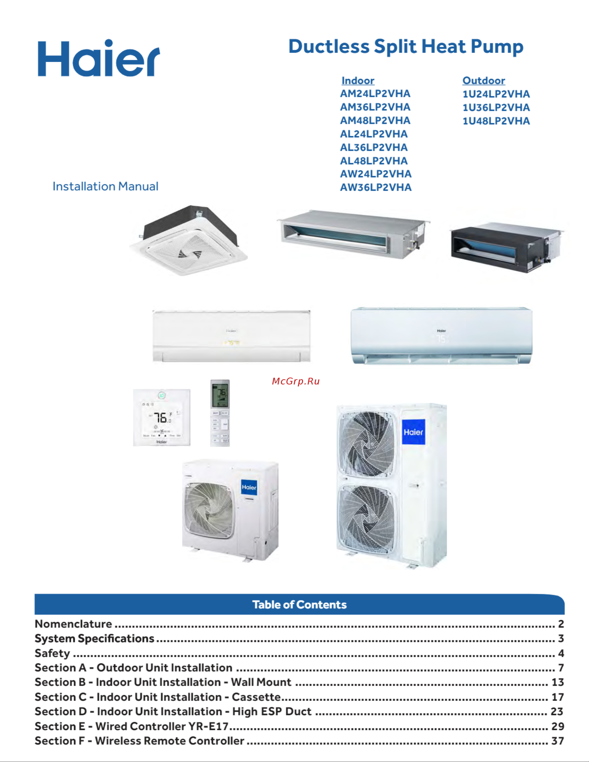
Haier Installation Manual Ductless Split Heat Pump Indoor AM24LP2VHA AM36LP2VHA AM48LP2VHA AL24LP2VHA AL36LP2VHA AL48LP2VHA AW24LP2VHA AW36LP2VHA Outdoor 1U24LP2VHA 1U36LP2VHA 1U48LP2VHA Table of Contents Nomenclature 2 System Specifications 3 Safety 4 Section A Outdoor Unit Installation 7 Section B Indoor Unit Installation Wall Mount 13 Section C Indoor Unit Installation Cassette 17 Section D Indoor Unit Installation High ESP Duct 23 Section E Wired Controller YR E17 29 Section F Wireless Remote Controller 37