
Zotek ZT-QB9 Инструкция по эксплуатации онлайн
3
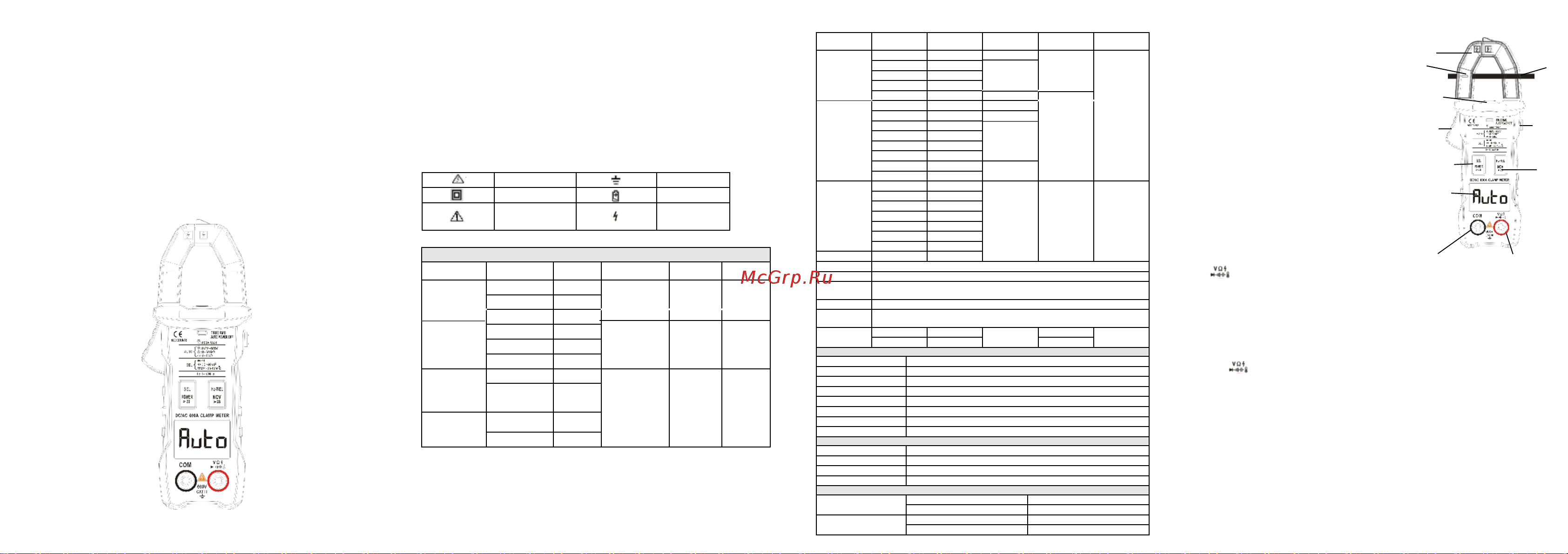
A. Introduction
This product is a battery-powered, true-rms, auto ranging digital clamp multimeter with a 6000 counts
LCD display and a backlight.
B. Safety Information
To avoid possible electrical shock, fire, or personal injury, please read all safety information before
you use the product.
(1) Do NOT exceed the “maximum value” indicated in the Specification.
(2) Examine the connection of the test leads and the insulation of the product before measuring
voltage higher than 36V DC or 25V AC.
(3) Disconnect the test leads from the circuit before changing the mode。
(4) Misuse of mode or range can lead to hazards, be cautious. “OL” will be shown on the display when
the input is out of range.
(5) Safety symbols:
C. Specifications
Hazardous Voltage
Earth
Double Insulated Low Battery
Risk of Danger. Check
the User Manual.
N/ L Wire
Judgement
- 1 - - 3 -
- 4 -
- 2 -
Electrical Specifications
Function Range Resolution Accuracy MAX.Value
Frequency
Response
DC Voltage
(V)
6.000V
0.001V
±(0.5%+3) 600V
60.00V
0.01V
AC Voltage
(V)
600V
1V
±(1.0%+3) 600V
40Hz
-1kHz
6.000V
0.001V
60.00V
0.01V
600.0V
1V
DC Current
(A)
60.00A
0.01A
±(2.0%+3
0)
600A
600.0A
0.1A
AC Current
(A)
60.00A
0.1A
600.0A
0.1A
Function Range Resolution Accuracy Max value
Frequency
response
Resistance
6.000k
Ω
0.001k
Ω ±(1.5%+3)
±(0.5%+3)
60MΩ
60.00k
Ω
0.01k
Ω
600.0k
Ω
0.1k
Ω
6.000M
Ω
0.001M
Ω
60.00M
Ω
0.01M
Ω ±(1.5%+3)
Capacitance
6.000nF
0.001nF
±(5.0%+20)
60.00mF
60.00nF
0.01nF
±2.0%+5
600.0nF
0.1nF
6.000μ
F
0.001
μF
60.00μ
F
0.01
μF
600.0μ
F
0.1
μF
6.000mF
0.001mF
±(5.0%+5)
60.00mF
0.01mF
Frequency
6.000Hz
0.001Hz
±(0.1%+2) 1.000MHz
60.00Hz
0.01Hz
600.0Hz
0.1Hz
6.000kHz
0.001kHz
60.00kHz
0.01kHz
600.0kHz
0.1kHz
6.000MHz
0.001MHz
10.00MHz
0.01MHz
Diode
√
Continuity
√
Inrush
Current
√
Peak hold
√
Fleshlight/ba
cklight
√
Temperature
(
-
30~1000)℃
1℃
±
(2.5%+5
)
1000℃
(
-
22~1832)℉
1℉
1832℉
General Specifications
Display(LCD) 6000counts
Range Auto
Material ABS
Update Rate
3times/second
Ture RMS
√
Data Hold
√
Low Battery Alert
√
Auto power off √
Mechanical Specifications
Dimension
172*64*32mm
Weight 161g
Battery type 1.5V AA battery * 2
Warranty One year
Environmental Specifications
Operating
Temperature
0~40℃
Humidity
<75%
Storage
Temperature
-20~60℃
Humidity
<80%
1
2
4
8
9
6
5
7
40Hz-1kHz
40Hz-1kHz
40Hz-1kHz
10
11
User Manual
±(5.0%+20)
D. Instruction
(1) Front Panel(see the picture on the right)
1. Jaw
2. Flashlight
3. Jaw release
4. Hold / Inrush Current / Peak Hold
HOLD: To press this button once and you will see
“HOLD” on the display;
Inrush current: To press this button twice
and you will see “INRUSH” on the display;
Peak hold: To press this button twice after
connecting test leads to the Terminals and you
will see “Peak HOLD” on the display;
5. Power / Select
Power: Press this button for more than 2 seconds
to turn it on / off.
Select: Press this button for switching functions
after connecting test leads to the Terminals.
6. Frequency / NCV: Press this button over 2 seconds
into NCV mode and exit from release.
7. LCD display
8. COM: Common terminal for all measurements.
9. : Input terminal for voltage, resistance, capacitance, temperature, frequency,
continuity, diode measurements and judging N/L wires.
10. Wire to be measured
11. Marked position
(2) Measure AC/DC Voltage
1. The minimum voltage of this product is 0.8V. When the measured voltage is higher
than 0.8V, the product will display the reading;
2. Connect the black test lead to the COM Terminal and connect the red test lead to
the Terminal;
3. The DC or AC voltage will be matched automatically;
4. Touch the probes to the correct test points of the circuit to measure the voltage;
5. Read the measured voltage on the display.
*Caution:
a. Do not measure voltage that exceeds the MAX Value as indicated in the
Specifications;
b. Do not touch high voltage circuit during measurements.
(3) Measure AC Current Only
1. Turn power switch on
2. Push the jaw release and center the wire within the clamp jaws (as in the picture).
The wire should be in the marked position to keep measurement accuracy.
3. Read the measured current on the display.
Содержание
- 1 3 4 2 1
- 1 front panel see the picture on the right 1
- 2 measure ac dc voltage 1
- 3 measure ac current only 1
- A do not measure voltage that exceeds the max value as indicatedin the 1
- B do not touch high voltage circuit during measurements 1
- Connect the black test lead to the com terminal and connect the red test lead to 1
- Continuity diode measurements and judging n l wires 1
- D instruction 1
- Frequency ncv press this button over 2 seconds 1
- Hold to press this button once and you will see hold on the display inrush current to press this button twice and you will see inrush on the display peak hold to press this button twice after connecting test leads to the terminals and you 1
- Into ncv mode and exit from release 1
- Jaw 2 flashlight 3 jaw release 4 hold inrush current peak hold 1
- Lcd display 8 com common terminal for all measurements 9 input terminal for voltage resistance capacitance temperature frequency 1
- Power press this button for more than 2 seconds to turn it on off select press this button for switching functions after connecting test leads to the terminals 1
- Power select 1
- Read the measured current on the display 1
- Specifications 1
- Than 0 v the product will display the reading 1
- The dc or ac voltage will be matched automatically 4 touch the probes to the correct test points of the circuit to measure the voltage 5 read the measured voltage on the display caution 1
- The minimum voltage of this product is 0 v when the measured voltage is higher 1
- The terminal 1
- The wire should be in the marked position to keep measurement accuracy 1
- Turn power switch on 2 push the jaw release and center the wire within the clamp jaws as in the picture 1
- User manual 1
- Will see peak hold on the display 1
- Wire to be measured 11 marked position 1
- 5 7 8 6 2
- 5 when is shown on the display batteries shall be replaced as below 2
- 8 measure ncv 2
- A disconnect circuit power and discharge all capacitors before you test 2
- And limitation of liability 2
- Connect the black test lead to the com terminal and the red lead to the 2
- E general maintenance 2
- If your product do not function as normal the following steps may help you if the 2
- Limited warranty 2
- Press sel power once to toggle to the temperature mode after 2
- The product automatically powers off after 15 minutes of inactivity 2
- Turn off the product and remove the test leads from the test points before 2
Похожие устройства
- Zotek ZT-QB4 Инструкция по эксплуатации
- Zotek ZT-QB3 Инструкция по эксплуатации
- Zotek ZT-QB1 Инструкция по эксплуатации
- Zotek ZT-5BQ Инструкция по эксплуатации
- Zotek VC903 Инструкция по эксплуатации
- Zotek VC902 Инструкция по эксплуатации
- Zotek ZT-550B+ Инструкция по эксплуатации
- Zotek ZT-320B+ Инструкция по эксплуатации
- Zotek GM-550 Инструкция по эксплуатации
- Zotek GM-320 Инструкция по эксплуатации
- Zotek ZT-E8 (International Type) Инструкция по эксплуатации
- Zotek ZT-E4 (US Type) Инструкция по эксплуатации
- Zotek ZT-E2 (EU Type) Инструкция по эксплуатации
- Zotek ZT-E10 (UK Type) Инструкция по эксплуатации
- Zotek ZT-TC13 Инструкция по эксплуатации
- Zotek ZT-DB02 Инструкция по эксплуатации
- Oxgard Praktika T-05-SMK-900 Инструкция по монтажу
- Oxgard Praktika T-06-CM-660 Инструкция по монтажу
- Oxgard Praktika T-06-CM-900 Инструкция по монтажу
- Oxgard Praktika T-06-CMK-660 Инструкция по монтажу