
Aten VK112EU Краткое руководство по установке контроллера онлайн
A
Panoramica dell'Hardware
1
Bottoni
Il layout è personalizzato usando da 6 a 12 bottoni.
2
Bottoni dei LEDs
• Le luci arancioni indicano che il bottone sta fornendo elettricità.
• Le luci bianche indicano che il bottone è attivato ed in operazione.
• Luci che alternano arancione e bianco indicano un aggiornamento
in corso.
3
Indicatori del sistema LED
• LAN: le luci verdi indicano che il VK112EU è connesso alla
Connessione Locale.
• Link: le luci verdi indicano che il VK112EU è connesso alla console di
controllo assegnata.
4
Bottone per il reset
Per resettare la rete, clicca "default settings".
5
Per alimentazione CC
Connetti l'adattatore ala morsettiera.
6
Interruttore ID del tastierino
Imposta l'ID del VK112EU.
7
ID interruttore scatola di controllo
Assegna il VK112EU ad una console di controllo semplicemente
specifi cando l'ID della console.
8
Porta LAN
• Connetti il VK112EU alla LAN.
• Fornisci corrente usando un cavo Ethernet.
B
Installazione
Punto 1 Preparare il sito installazione
Installare il tastierino sulla superfi cie che si preferisce, con o senza
una scatola da muro a 2 moduli. Segui il diagramma qua sopra per
preparare il sito di installazione con le dimensioni specifi cate per
accogliere il dispositivo.
Punto 2 Installare il tastierino
2.1 Usa l’interruttore ID del tastierino per impostare un ID per l’unità,
e imposta l’interruttore ID della console di controllo sull’ID della
console di controllo alla quale vuoi connetterti.
2.2 Connetti i cavi necessari per l'alimentazione e il collegamento di
rete del tastierino. Esegui una delle seguenti operazioni:
• Usa un cavo Ethernet per connettere il tastierino a un
interruttore PoE.
• Usa un cavo Ethernet per connettere il tastierino alla LAN e un
adattatore di alimentazione per collegarlo alla rete elettrica.
Per ulteriori informazioni su come installare una morsettiera
sull'adattatore per l'alimentazione, vedi il manuale d'uso di
ATEN Control System.
Nota: La tastiera adotta l'indirizzo IP predisposto (192.168.0.60)
in caso che l'interruttore di rete non supporti il DHCP. Per
confi gurare l'indirizzo IP, accedi all'interfaccia web usando
l'indirizzo IP predisposto e la password preimpostata (password).
2.3 Fissa il tastierino alla scatola da parete o alla superfi cie che hai
scelto.
2.4 Installa i capitasti e la copertura.
Confi gurazione
Usa il confi guratore ATEN per creare o caricare un'interfaccia di
controllo (Visore) per il tastierino. Per informazioni dettagliate vedi il
manuale d'uso di ATEN Control System.
Sistema di controllo VK 112 EU ATEN – Tastiera da 12 bottoni (EU, 2 Gang)
www.aten.com
A
Vista general del hardware
1
Botones
El diseño es personalizable usando 6 a 12 botones.
2
LEDs de botones
• se ilumina en naranja para indicar que el botón está alimentado.
• se ilumina en blanco para indicar que el botón está en funcionamiento.
• parpadea en naranja y blanco para indicar que la actualización del
fi rmware está en curso.
3
Indicadores LED del sistema
• LAN: se ilumina en verde para indicar que el VK112EU está
conectado a la LAN.
• Link: se ilumina en verde para indicar que el VK112EU está
conectado a la caja de control asignada.
4
Pulsador de reinicio
Presionar para restablecer la red a la confi guración predeterminada.
5
Alimentación DC
Conecte el adaptador de corriente al bloque de terminales.
6
Conmutador de identifi cación del teclado
Ajusta la identifi cación del VK112EU.
7
Conmutador ID de caja de control
Asigna el VK112EU a una caja de control especifi cando la
identifi cación de la caja de control.
8
Puerto LAN
• Conecta el VK112EU a la LAN.
• Suministra energía a través de Ethernet mediante un cable Ethernet.
B
Instalación
Paso 1 Prepare el lugar de instalación
Instale el Teclado en una superfi cie elegida con o sin una caja eléctrica
doble. Consulte el diagrama de recorte anterior para preparar el lugar
de instalación con las dimensiones especifi cadas para acomodar el
dispositivo.
Paso 2 Instale el teclado
2.1 Utilice el conmutador de identifi cación del teclado para establecer
una identidad para la unidad y confi gure el conmutador de
identifi cación de la caja de control según la identifi cación de la
caja de control a la que desea conectarse.
2.2 Conecte los cables necesarios para el suministro eléctrico y
conectividad de red al teclado. Realice una de las siguientes
acciones:
• Utilice un cable Ethernet para conectar el teclado a un
conmutador PoE.
• Utilice un cable Ethernet para conectar el teclado a la LAN y un
adaptador de corriente para suministrar energía. Para obtener
más información sobre la instalación de un bloque de terminales
al adaptador de corriente, consulte el Manual del usuario del
sistema de control ATEN.
Nota: El teclado adopta la dirección IP predeterminada
(192.168.0.60) si el conmutador de red no soporta DHCP. Para
cambiar la dirección IP, inicie sesión en la interfaz web utilizando
la dirección IP predeterminada con la contraseña predeterminada
(contraseña).
2.3 Asegure el teclado a la caja eléctrica o a la superfi cie elegida.
2.4 Instale las tapas de los botones y la placa frontal.
Confi guración
Utilice el Confi gurador ATEN para crear y cargar una interfaz de
control (visor) para el teclado. Para obtener más información, consulte
el Manual del usuario del sistema de control ATEN.
Sistema de control VK112EU ATEN - Teclado de 12 botones (EU, 2 Gang)
www.aten.com
A
Hardware Übersicht
1
Tasten
Das Layout ist mit 6 bis 12 Tasten anpassbar.
2
Tasten-LEDs
• leuchtet orange, um anzuzeigen, dass die Taste mit Strom versorgt
wird.
• leuchtet weiß, um anzuzeigen, dass die Taste in Betrieb ist.
• blinkt orange und weiß, um anzuzeigen, dass die Firmware-
Aktualisierung läuft.
3
System LED-Anzeigen
• LAN: leuchtet grün, um anzuzeigen, dass das VK112EU mit dem
LAN verbunden ist.
• Link: leuchtet grün, um anzuzeigen, dass das VK112EU an die
zugeordnete Kontrollbox angeschlossen ist.
4
Zurücksetzen Drucktaste
Hier drücken, um das Netzwerk auf die Standardeinstellungen
zurückzusetzen.
5
Gleichstrom
Schließen Sie das Netzteil an den Anschlussblock an.
6
Keypad ID Switch
Legt die ID des VK112EU fest.
7
Kontrollbox ID Switch
Weist das VK112EU einer Kontrollbox zu, indem es die ID der
Kontrollbox angibt.
8
LAN Port
• Verbindet das VK112EU mit LAN.
• Stromversorgung über Ethernet mittels Ethernetkabel.
B
Installation
Schritt 1 Vorbereitung des Montageortes
Installieren Sie das Keypad auf einer ausgewählten Oberfl äche
mit oder ohne 2-Gang Wanddose. Verwenden Sie das obige
Ausschnittsschema, um den Installationsort mit den angegebenen
Abmessungen für die Aufnahme des Geräts vorzubereiten.
Schritt 2 Installation des Keypads
2.1 Weisen Sie mit dem Keypad ID Switch eine ID für das Gerät
zu, und stellen Sie den Kontrollbox ID Switch auf die ID der
Kontrollbox ein, mit der Sie eine Verbindung herstellen möchten.
2.2 Fädeln Sie die erforderlichen Kabel ein, um das Keypad mit Strom
zu versorgen und Netzwerkkonnektivität herzustellen. Gehen Sie
wie folgt vor:
• Verwenden Sie ein Ethernet-Kabel, um das Keypad mit einem
PoE-Switch zu verbinden.
• Verwenden Sie ein Ethernet-Kabel, um das Keypad mit dem LAN
zu verbinden, und ein Netzteil zur Stromversorgung. Weitere
Informationen zur Installation eines Anschlussblocks am Netzteil
fi nden Sie im Benutzerhandbuch für das ATEN Kontrollsystem.
Hinweis: Das Keypad übernimmt die Standard IP-Adresse
(192.168.0.60), wenn der Netzwerk-Switch DHCP nicht
unterstützt. Um die IP-Adresse zu ändern, melden Sie sich mit der
Standard IP-Adresse mit dem Standardkennwort (password) am
Web-Interface an.
2.3 Befestigen Sie das Keypad an der Wanddose oder der gewählten
Oberfl äche.
2.4 Installieren Sie die Tastenkappen und die Frontplatte.
Konfi guration
Verwenden Sie den ATEN Konfi gurator, um eine Kontrollschnittstelle
(Viewer) für das Keypad zu erstellen und hochzuladen. Detaillierte
Informationen fi nden Sie im ATEN Kontrollsystem Benutzerhandbuch.
VK112EU ATEN Kontrollsystem - 12-Tasten Keypad (EU, 2 Serie)
www.aten.com
A
Survol du matériel
1
Boutons
La mise en page est personnalisable à l'aide de 6 à 12 boutons.
2
Bouton LED
• s'éclaire en orange pour indiquer que le bouton est sous tension.
• s'éclaire en blanc pour indiquer que le bouton est en marche.
• Clignote orange et blanc pour indiquer que le mise à jour du micro
logiciel est en cours.
3
Indicateurs LED
• LAN : s'allume en vert pour indiquer que le VK112EU est connecté
au réseau local.
• Link : s'allume en vert pour indiquer que le VK112EU est connecté à
la boîte de commande assignée.
4
Bouton de Réinitialisation
Appuyez pour rétablir le réseau par défaut.
5
Courant continu
Branchez l'adaptateur secteur au bloc de connexion.
6
Commutateur d’ID de clavier
Règle l'ID du VK112EU.
7
Commutateur d'identifi ant du boîtier de commande
Assigne le VK112EU à un boitier de commande en spécifi ant l'ID du
boitier de commande.
8
Port LAN
• Raccorde le VK112EU au LAN.
• Alimente l'Ethernet avec un câble Ethernet.
B
Installation
Étape 1 Préparer le site d'installation
Installez le clavier sur une surface sélectionnée avec ou sans un boîtier
mural à 2 bandes. Consultez le diagramme en coupe ci-dessus pour
préparer le site d'installation selon les dimensions précisées pour y
arranger l'appareil.
Étape 2 Installez le Clavier
2.1 Utilisez le commutateur d’ID de clavier pour défi nir une ID pour
l’unité et programmez le commutateur d’ID de boîtier de contrôle
sur l’ID du boîtier de contrôle sur lequel vous souhaitez vous
connecter.
2.2 Passez les câbles requis pour fournir du courant et une connexion
au réseau pour le Clavier. Utilisez une des méthodes suivantes :
• Utilisez un câble Ethernet pour connecter le Clavier à un
commutateur PoE.
• Utilisez un câble Ethernet pour connecter le Clavier au LAN et
un adaptateur électrique pour fournir du courant. Pour plus
d'informations sur comment installer un bloc de jonction à
l'adaptateur électrique, consultez le Mode d'Emploi du Système
de Commande ATEN.
Remarque : Le Clavier adopte l'adresse IP par défaut
(192.168.0.60) si le commutateur de réseau ne supporte pas
DHCP. Pour changer d'adresse IP, connectez-vous à l'interface web
en utilisant l'adresse IP par défaut et le mot de passe par défaut
(mot de passe).
2.3 Sécurisez le Clavier au coffret mural ou à la surface choisie.
2.4 Installez les capuches de bouton sur la plaque avant.
Confi guration
Utilisez le Confi gurateur ATEN pour créer et charger une interface
de commande (Visualiseur) pour le Clavier. Pour plus d'informations,
consultez le Mode d'Emploi du Système de Commande ATEN.
Système de Contrôle VK112EU ATEN - Clavier à 12 Touches (EU, 2 Gang)
www.aten.com
A
Hardware Overview
1
Buttons
The layout is customizable using 6 to 12 buttons.
2
Button LEDs
• lights orange to indicate that the button is supplied with power.
• lights white to indicate that the button is in operation.
• blinks orange and white to indicate that fi rmware upgrade is in
progress.
3
System LED Indicators
• LAN: lights green to indicate that the VK112EU is connected to LAN.
• Link: lights green to indicate that the VK112EU is connected to the
assigned Control Box.
4
Reset Pushbutton
Press to reset the network to default settings.
5
DC Power
Connect the power adapter into the terminal block.
6
Keypad ID Switch
Sets the ID of the VK112EU.
7
Control Box ID Switch
Assigns the VK112EU to a Control Box by specifying the Control Box’s
ID.
8
LAN Port
• Connects the VK112EU to LAN.
• Supplies Power over Ethernet using an Ethernet cable.
B
Installation
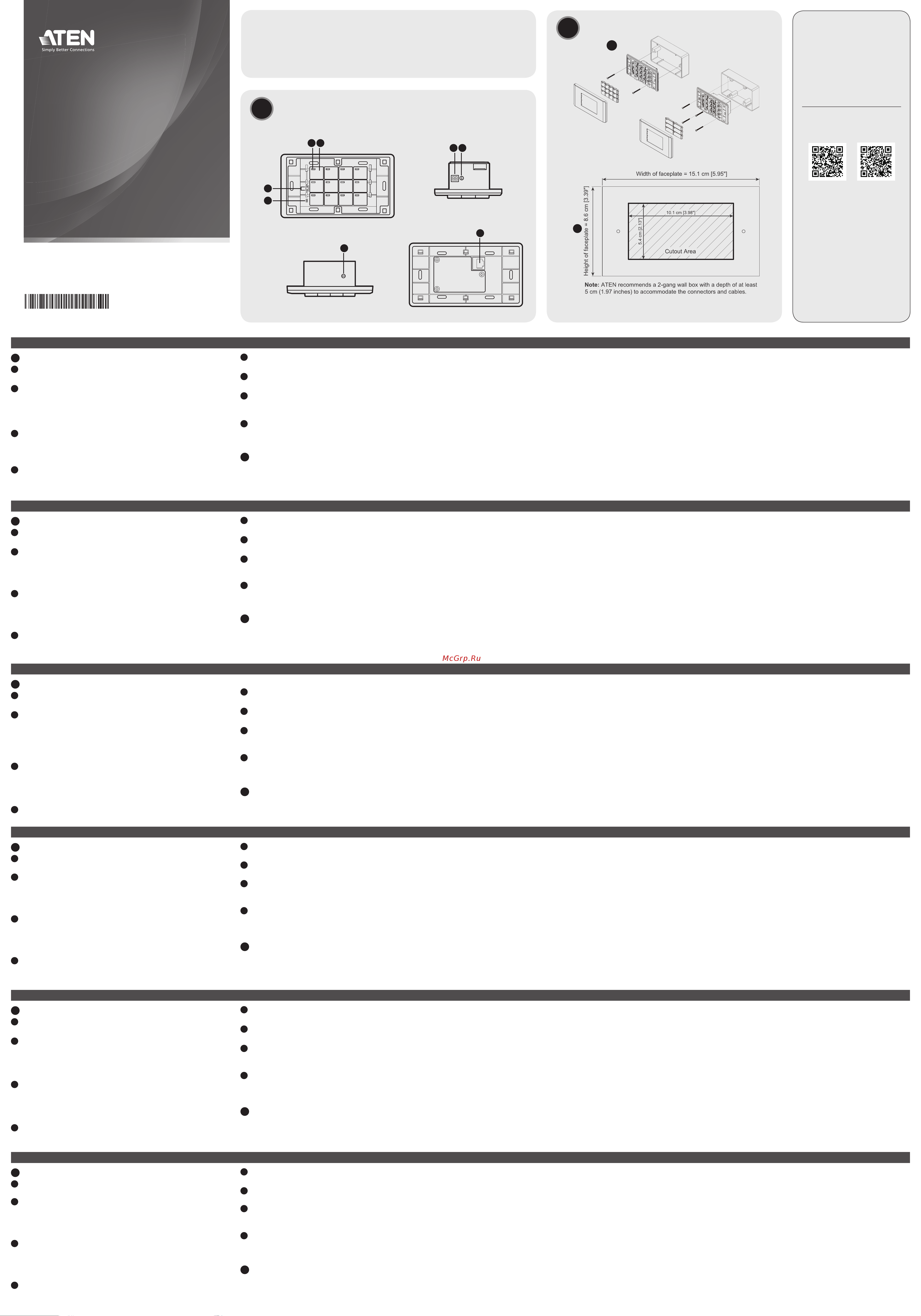
Step 1 Prepare the installation site
Install the Keypad into a chosen surface with or without a 2-gang wall
box. Refer to the cutout diagram above to prepare the installation site
with the specifi ed dimensions to accommodate the device.
Step 2 Install the Keypad
2.1 Use the keypad ID switch to set an ID for the unit, and set the
control box ID switch to the ID of the control box to which you
wish to connect.
2.2 Thread the required cables to supply power and network
connectivity to the Keypad. Do one of the following:
• Use an Ethernet cable to connect the Keypad to a PoE switch.
• Use an Ethernet cable to connect the Keypad to LAN and a
power adapter to supply the power. For more information about
installing a terminal block to the power adapter, refer to the
ATEN Control System User Manual.
Note: The Keypad adopts the default IP address (192.168.0.60)
if the network switch does not support DHCP. To change the IP
address, log in the web interface using the default IP address with
the default password (password).
2.3 Secure the Keypad to the wall box or the chosen surface.
2.4 Install the button caps and the faceplate.
Confi guration
Use ATEN Confi gurator to create and upload a control interface
(Viewer) for the Keypad. For detailed information, see ATEN Control
System User Manual.
VK112EU ATEN Control System – 12-Button Keypad (EU, 2 Gang)
www.aten.com
B
Package Contents
1 VK112EU 12-Button Keypad
1 button pack
1 terminal block
1 faceplate
1 user instructions
© Copyright 2021 ATEN
®
International Co. Ltd.
ATEN and the ATEN logo are registered trademarks of ATEN International Co., Ltd.
All rights reserved. All other trademarks are the property of their respective owners.
Part No. PAPE-1223-K60G Released: 11/2021
ATEN Control System – 12-Button Keypad
(EU, 2 Gang)
Quick Start Guide
VK112EU
ATEN VanCryst
™
A
Hardware Overview
3
MK Type
EU Type
3
4
2 1
5 7
6
8
Installation
Support and Documentation Notice
All information, documentation, fi rmware,
software utilities, and specifi cations
contained in this package are subject to
change without prior notifi cation by the
manufacturer.
To reduce the environmental impact of
our products, ATEN documentation and
software can be found online at
http://www.aten.com/download/
Technical Support
www.aten.com/support
Scan for more information
1
ATEN Website User Manual
Front View Bottom View
Side View Rear View
A
Основные элементы
1
Кнопки
Модифицируемая компоновка с использованием от 6 до 12 кнопок.
2
СД-индикаторы кнопок
• горит оранжевым, показывая, что к кнопке подается питание.
• горит белым, показывая, что операция кнопки активирована.
• мигает оранжевым и белым, показывая, что выполняется
обновление микропрограммы.
3
СД-индикаторы системы
• LAN: горит зеленым, показывая, что VK112EU подсоединена к
сети LAN.
• Link: горит зеленым, показывая, что VK112EU подсоединена к
заданному блоку управления.
4
Кнопка сброса
Используется для сброса настроек сети к базовым значениям.
5
Питание постоянного тока
Подсоедините к клеммнику адаптер питания.
6
Селектор ID-кода клавиатуры
Задает ID-код VK112EU.
7
Селектор ID-кода блока управления
Подключает VK112EU к блоку управления путем выбора ID-кода этого
блока управления.
8
Порт LAN
• Подключает VK112EU к сети LAN.
• Поставляет питание PoE (питание по Ethernet) по кабелю Ethernet.
B
Установка
Шаг 1 Подготовьте место установки
Установите кнопочную панель на выбранную поверхность с
помощью монтажной коробки на 2 секции или без нее. См.
вырезаемую схему выше, чтобы подготовить место установки с
указанными размерами для размещения устройства.
Шаг 2 Установите кнопочную панель
2.1 Задайте ID клавиатуры с помощью селектора ID-кода
клавиатуры, затем на селекторе ID-кода блока управления
выберите ID подключаемого блока управления.
2.2 Присоедините необходимые кабели для подачи питания на
кнопочную панель и подключения ее к сети. Выполните одно
из следующих действий.
• Используйте кабель Ethernet для подключения панели к
коммутатору PoE.
• Используйте кабель Ethernet для подключения панели к
сети LAN и адаптеру питания. Подробнее об установке
клеммной колодки на адаптере питания см. в руководстве
пользователя по системе управления ATEN.
Примечание: Кнопочная панель использует IP-адрес по
умолчанию (192.168.0.60), если сетевой коммутатор не
поддерживает DHCP. Чтобы изменить IP-адрес, войдите
в веб-интерфейс с помощью IP-адреса по умолчанию с
паролем по умолчанию (password).
2.3 Прикрепите кнопочную панель к монтажной коробке или
выбранной поверхности.
2.4 Установите элементы кнопок и лицевую панель.
Настройка
Используйте конфигуратор ATEN, чтобы создать и загрузить
интерфейс управления (программу просмотра) для кнопочной
панели Подробнее см. в руководстве пользователя по
системе управления ATEN.
Система управления ATEN VK112EU — 12-кнопочная клавиатура (EU, 2 секции)
www.aten.com
Содержание
- Confi guración 1
- Confi guration 1
- Confi gurazione 1
- Hardware overview 1
- Hardware übersicht 1
- Instalación 1
- Installation 1
- Installazione 1
- Konfi guration 1
- Panoramica dell hardware 1
- Survol du matériel 1
- Vista general del hardware 1
- Vk112eu 1
- Настройка 1
- Основные элементы 1
- Установка 1
- Adım kurulum yerini hazırlayın 2
- Adım tuş takımını kurun 2
- Botão de reiniciar 2
- Botões 2
- Configuração 2
- Dc güç 2
- Dc 电源 2
- Dc 電源 2
- Donanım kurulumu 2
- Donanıma genel bakış 2
- Düğme led leri 2
- Düğmeler 2
- Energia dc 2
- Indicadores led do sistema 2
- Instalação 2
- Interruptor id caixa de controlo 2
- Interruptor id keypad 2
- Kontrol kutusu kimliği anahtarı 2
- Lan bağlantı noktası 2
- Lan порт 2
- Lan ポート 2
- Lan 埠 2
- Lan 端口 2
- Lan 포트 2
- Leds do botão 2
- Passo 1 preparar o local de instalação 2
- Passo 2 instalar o teclado 2
- Porta lan 2
- Sistem led göstergesi 2
- Step 1 설치 위치 선택 2
- Step 2 키패드 설치 2
- Sıfırlama düğmesi 2
- Tuş takımı kimliği anahtarı 2
- Vista geral do hardware 2
- Yapılandırma 2
- Встановлення 2
- Живлення постійного струму 2
- Кнопка скидання 2
- Кнопки 2
- Кнопки світлодіоди 2
- Конфігурація 2
- Крок 1 підготуйте місце встановлення 2
- Крок 2 встановіть клавіатуру 2
- Огляд устаткування 2
- Перемикач ідентифікатора блока керування 2
- Перемикач ідентифікатора клавіатури 2
- Системні світлодіодні індикатори 2
- キーパッド id スイッチ 2
- コントロールボックス id スイッチ 2
- システム led ランプ 2
- ボタン 2
- ボタン led 2
- リセットボタン 2
- 安装 2
- 安裝 2
- 手順 1 設置場所の準備 2
- 手順 2 キーパッドの取り付け 2
- 按鍵 2
- 按鍵 led 指示燈 2
- 按键 2
- 按键 led 2
- 按键面板 id 旋钮 2
- 控制器 id 旋钮 2
- 控制盒 id 開關 2
- 構成 2
- 步驟 1 準備安裝地點 2
- 步驟 2 安裝鍵盤 2
- 硬件概览 2
- 硬體檢視 2
- 第 1 步 准备好安装点 2
- 第 2 步 安装按键面板 2
- 系統 led 指示燈 2
- 系统 led 指示灯 2
- 組態 2
- 製品各部名称 2
- 設置 2
- 配置 2
- 重置按鈕 2
- 重置按钮 2
- 鍵盤 id 開關 2
- 구성 2
- 리셋 누름버튼 2
- 버튼 2
- 버튼 led 2
- 설치 2
- 시스템 led 지시등 2
- 직류전원 2
- 컨트롤 박스 id 스위치 2
- 키패드 id 스위치 2
- 하드웨어 개요 2
Похожие устройства
- Aten VK112EU Руководство пользователя
- Aten VK108US Краткое руководство по установке
- Aten VK108US Руководство пользователя
- Aten VM0202HB Краткое руководство по установке
- Aten VM0202HB Руководство пользователя
- Aten VM0808HB Краткое руководство по установке
- Aten VM0808HB Руководство к Приложению для управления видеоматрицей
- Aten VM0808HB Руководство пользователя
- Aten VM0404HB Краткое руководство по установке
- Aten VM0404HB Руководство к Приложению для управления видеоматрицей
- Aten VM0404HB Руководство пользователя
- Aten VM0202H Краткое руководство по установке
- Aten VM0202H Руководство пользователя
- Aten VM0404HA Руководство пользователя
- Aten VM0404HA Краткое руководство по установке
- Aten VM5808HA Краткое руководство по установке
- Aten VM5808HA Руководство пользователя
- Aten VM5404HA Краткое руководство по установке
- Aten VM5404HA Руководство пользователя
- Aten VM6404HB Краткое руководство по установке