
Yamaha XS360 (1976-1982) Инструкция по эксплуатации онлайн
Содержание
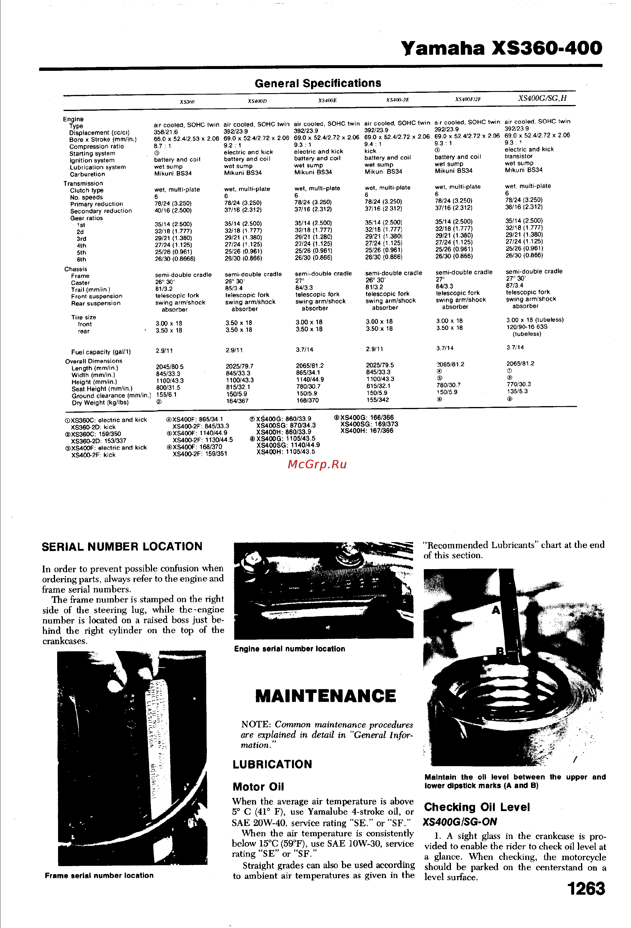
- A sight glass in the crankcase is pro 1
- Below 15 c 59 f use sae 10w 30 service rating se or sf 1
- Checking oil level xs400gisg on 1
- General specifications ________________ 1
- In order to prevent possible confusion when ordering parts always refer to the engine and frame serial numbers 1
- Lubrication 1
- Maintenance 1
- Motor oil 1
- Note common maintenance procedures are explained in detail in general infor mation 1
- Recommended lubricants chart at the end of this section 1
- Serial number location 1
- Side of the steering lug while the engine number is located on a raised boss just be hind the right cylinder on the top of the crankcases 1
- Straight grades can also be used according 1
- The frame number is stamped on the right 1
- To ambient air temperatures as given in the 1
- Vided to enable the rider to check oil level at a glance when checking the motorcycle should be parked on the centerstand on a level surface 1
- When the air temperature is consistently 1
- When the average air temperature is above 5 c 41 f use yamalube 4 stroke oil or sae 20w 40 service rating se or sf 1
- Yamaha xs360 400 1
- Changing oil 2
- Filter screen 2
- Front forks 2
- Oil filter 2
- Other models 2
- Yamaha xs360 400 2
- Chassis lubrication 3
- Clutch 3
- Drive chain 3
- Service checks and adjustments 3
- Yamaha xs360 400 3
- Brakes front disc 4
- Rear disc 4
- Throttle cable 4
- Yamaha xs360 400 4
- Brake light switches 5
- Front drum 5
- Fuel system 5
- Headlight adjustment 5
- Petcock 5
- Rear drum 5
- Yamaha xs360 400 5
- Air filters 6
- Although major overhaul of the carbu 6
- Blow out the elements from the inside 6
- Carburetors 6
- Caution do not let gasoline spill on a hot engine 3 remove the four screws which secure 6
- Check the sealing washer and replace it 6
- Clean the filter screen in a solvent be 6
- Disconnect the fuel line from the petcock and the vacuum line from the manifold 6
- Each float bowl and carefully lower the bowls until they are clear of the float mechanism 6
- If it is damaged 6
- Install the petcock after the tank is 6
- Install them 6
- Intervals 6
- Maintenance data 6
- Make sure that the petcock is shut off 6
- Note after several such cleanings the elements should be replaced with new ones the service interval for replacement will depend upon the amount of dirt build up on the elements 5 refit the elements into their cases and 6
- Periodic maintenance 6
- Pilot jets these are fitted to the float bowl on 360 models and are on the carburetor bodies on 400 models blow the jets clear then rein stall clean any foreign matter out of the float bowls when installing position the bowls carefully to avoid damage to the floats tighten the screws gradually and evenly check for fuel leaks before operation 6
- Recommended lubricants 6
- Refitted check for leaks before operating the motorcycle 6
- Remove the case screws and separate 6
- Remove the gas tank drain off the fuel 3 unscrew the petcock securing nut or 6
- Remove the side covers 2 loosen the carburetor clamp remove 6
- Res position drain the fuel from the car buretor float bowls by removing the main jet cover bolt from the bottom of the float bowls 6
- Retors requires their removal as a unit the float bowls and jets can be cleaned with the units in place 6
- Set the petcock to the res position 6
- Sure to remove any foreign matter trapped in the screen as this will impede fuel flow if the screen cannot be cleaned or if it is punc tured or otherwise damaged it should be re placed 6
- The case halves removing the filter element 6
- The element case holder screw take off the securing band and remove the element case 6
- Two phillips screws depending upon the method of fastening and pull off the petcock 6
- Unscrew and remove the main and 6
- With compressed air 6
- Yamaha xs360 400 6
- Cam chain adjustment 7
- Compression test 7
- Contact breaker points 7
- Location 7
- Replacement 7
- Tune up 7
- Valve adjustment 7
- Yamaha xs360 400 7
- Dynamic timing 8
- Gapping 8
- Ignition timing breaker point models 8
- Lubrication 8
- Yamaha xs360 400 8
- Adjusting float level 9
- Carburetors 9
- Ignition timing xs400g sg h 9
- Static timing 9
- Synchronization 9
- Yamaha xs360 400 9
- Connect the vacuum gauges 5 start the engine and note the vacuum 10
- Ders must be within 5 cm hg 0 in hg adjust if necessary by turning the synchro nization screw in or out until the vacuum readings for the two cylinders is as identical as possible 10
- Feed line if necessary so that the synchro nization screw between the carburetors is ac cessible 10
- Idle speed and mixture 10
- Idle speed is set by means of the throt 10
- If the limiter caps are missing or if the 10
- Manifolds the vacuum gauge fitting for the right cylinder operates the fuel petcock dis connect the petcock line from the fitting and turn the petcock to the prime position for the duration of the procedure 10
- Note if the vacuum gauges read more than 5 cm hg 0 in hg at 1 200 rpm check the compression spark plugs igni tion timing and valve clearance 6 if vacuum gauges are not available a 10
- Pilot screws have been removed as during a carburetor overhaul pilot screw adjustment is accomplished by screwing the pilot screws in very carefully until lightly seated then backing them out 1 turns on 360 models and 1 turns on 400 models 10
- Readings at idle 1 200 rpm the two cylin 10
- Rough method of synchronizing the carbu retors may be carried out remove the car buretors as a unit from the motorcycle look into the engine side of the carburetors and note the relative positions of the edges of the butterflies in relation to the small by pass passages in the bottom of the bores both butterflies should be in the same position relative to these by pass holes 10
- Screw fitted to each carburetor the screws are fixed in position by means of idle limiter caps this is designed to reduce emissions therefore it is not generally necessary to ad just the pilot screws 10
- The idle mixture is controlled by a pilot 10
- The vacuum gauge fittings are on the 10
- Tle stop screw between the carburetors idle speed is 1 200 rpm and must be adjusted when the engine is at operating temperature 10
- Tune up specifications 10
- Yamaha xs360 400 10
- Cylinder head removal 11
- Engine and transmission 11
- Engine removal and installation 11
- Engine service 11
- Top end 11
- Yamaha xs360 400 11
- Cylinder and piston removal 12
- Cylinder head 12
- Inspection camshaft 12
- Rocker arms and shafts 12
- Valve assembly 12
- Yamaha xs360 400 12
- Cylinders and pistons 13
- Lapping 13
- Seat cutting 13
- Yamaha xs360 400 13
- Cylinder and piston installation 14
- Cylinder head installation 14
- Piston rings 14
- Yamaha xs360 400 14
- Clutch removal 15
- Crankcase cover components 15
- Yamaha xs360 400 15
- Gearshift mechanism removal 16
- Inspection 16
- Installation 16
- Kickstarter shaft removal 16
- Oil pump 16
- Yamaha xs360 400 16
- Alternator starter drive removal 17
- Case assembly 17
- Engine sprocket removal 17
- Inspection 17
- Installation 17
- Lower end and transmission 17
- Splitting the crankcases 17
- Transmission gear shift assembly removal 17
- Yamaha xs360 400 17
- Assembly 18
- Crankshaft removal 18
- Inspection 18
- Yamaha xs360 400 18
- 1 blue 19
- 2 black 19
- Before installing connecting rods on the 19
- Berance is towards the intake side of the engine be sure that the rods are installed so that the cap numbers align with the rod num bers 19
- Big end bearing no crankpin no 19
- Brown green 19
- Coat the con rod bolt threads with a 19
- Crankcase no journal no insert 19
- Crankpins thoroughly lubricate the bearings with motor oil install the rods so that the yamaha mark on both rods faces the left end of the crankshaft and the bearing protu 19
- Engine specifications 19
- Going to be replaced be sure that the weight codes stamped on the rod and cap match for both rods 19
- If one or both of the connecting rods is 19
- Insert 19
- Molybdenum disulphide lubricant and 19
- Replace big end bearing inserts with in 19
- Rod side play at the small end if the move ment exceeds 0 mm 0 19 in the big end bearing should be replaced 19
- Serts of the same color code if the color is no longer visible on the old insert select a re placement according to the following chart 19
- Torque them to 24 28 ft lbs 19
- With a dial gauge check connecting 19
- Yamaha xs360 400 19
- Checking oil pressure 20
- Engine specifications cont 20
- Engine torque specifications 20
- Inspection 20
- Installation 20
- Lubrication system 20
- Oil pump 20
- Operational description 20
- Removal 20
- Yamaha xs360 400 20
- Carburetors 21
- Fuel system 21
- Installation 21
- Lubrication system specifications 21
- Removal 21
- Yamaha xs360 400 21
- Disassembly 22
- Inspection 22
- Yamaha xs360 400 22
- Alternator output check 23
- Assembly 23
- Carburetor specifications 23
- Charging system 23
- Electrical system 23
- Field coiliarmature tests 23
- Fuel petcock 23
- Yamaha xs360 400 23
- Breaker point ignition 24
- Pick up coil removal and installation 24
- Rectifier 24
- Regulator 24
- Transistorized ignition 24
- Troubleshooting 24
- Yamaha xs360 400 24
- Brake light 25
- Electrical components 25
- Inspection 25
- Neutral indicator 25
- Starter motor service removal and installation 25
- Starter solenoid 25
- Starting system 25
- Taillight 25
- Testing 25
- Turn signals 25
- Yamaha xs360 400 25
- Oil pressure indicator 26
- Self cancelling turn signal system 26
- Wiring diagrams 26
- Yamaha xs360 400 26
- Yamaha xs360 400 27
- J xs400fonly 28
- Wiring diagrams 28
- Xs400 2e 28
- Xs400f 2f 28
- Yamaha xs360 400 28
- Chassis 29
- Wiring diagrams 29
- Yamaha xs360 400 29
- Bleeding 30
- Disc brake service 30
- Flushing 30
- Precautions 30
- Rear wheel assembly removal and installation 30
- Tubeless tires 30
- Wheel bearings 30
- Yamaha xs360 400 30
- Caliper 31
- Front disc brake pad replacement 31
- Master cylinder 31
- Yamaha xs360 400 31
- Disc service 32
- Dissassembly 32
- Front drum brake 32
- Front forks 32
- Inspection 32
- Rear disc brake 32
- Rear drum brake 32
- Removal 32
- Yamaha xs360 400 32
- Assembly 33
- Bearing adjustment 33
- Disassembly 33
- Inspection 33
- Installation 33
- Steering stem assembly 33
- Yamaha xs360 400 33
- Assembly 34
- Inspection 34
- Rear shocks 34
- Removal and installation 34
- Swing arm 34
- Yamaha xs360 400 34
Похожие устройства
- Tesy GCH/L 12044 30 B12 TSR Инструкция по эксплуатации
- Yamaha XJR1300 (P) (2002) Инструкция по эксплуатации
- Tesy GCV 3036 16D A04 TS2R Инструкция по эксплуатации
- Yamaha XJR1300 (L) (1999) Инструкция по эксплуатации
- Tesy GCV 6036 20D A04 TS2R Инструкция по эксплуатации
- Yamaha XJ900S (G) (1995) Инструкция по эксплуатации
- Tesy GCV 8036 24D A04 TS2R Инструкция по эксплуатации
- Yamaha XJ750 (1980-1984) Инструкция по эксплуатации
- Tesy GCV 5045 16D A04 TS2R Инструкция по эксплуатации
- Yamaha XJ650 (1980-1984) Инструкция по эксплуатации
- Tesy GCV 8045 24D A04 TS2R Инструкция по эксплуатации
- Yamaha WR450FR (2003) Инструкция по эксплуатации
- Tesy GCV 10045 24D A04 TS2R Инструкция по эксплуатации
- Yamaha WR250FR (2002) Инструкция по эксплуатации
- Tesy GCV 12045 24D A04 TS2R Инструкция по эксплуатации
- Yamaha VMX12HC (1995) Инструкция по эксплуатации
- Tesy GCV 15045 24D A04 TS2R Инструкция по эксплуатации
- Yamaha VMX12H (1995) Инструкция по эксплуатации
- Tesy GCH[L] 8045 20D A04 TS2R ANTICALC Инструкция по эксплуатации
- Yamaha TZR250 (1987) Инструкция по эксплуатации
Yamaha XS360 400 General Specifications Engine Displacement cc ci Bore x Stroke mm in Compression ratio Starting system Ignition system Lubrication system Carburetion Transmission Clutch type No speeds Primary reduction Secondary reduction Gear ratios 1st 2d 3rd 4th 5th 6th Fuel capacity gal 1 Overall Dimensions Length mm in Width mm in Height mm in Seat Height mm in Ground clearance mm in Dry Weight kg lbs XS360C electric and kick XS360 2D kick XS360C 159 350 XS360 2D 153 337 XS400F electric and kick XS400 2F kick a r cooled SOHC twin 392 23 9 69 0 x 52 4 2 72 x 2 06 9 3 1 air cooled SOHC twin 392 23 9 69 0 x 52 4 2 72 x 2 06 9 3 i electric and kick transistor battery and coil wet sump Mikuni BS34 wet multi plate 6 78 24 3 250 40 16 2 500 wet multi plate 6 78 24 3 250 37 16 2 312 wet multi plate 6 78 24 3 250 37 16 2 312 wet multi plate 6 78 24 3 250 37 16 2 312 wet multi plate 6 78 24 3 250 37 16 2 312 wet multi plate 35 14 2 500 32 18 1 777 29 21 1 380 27 24 1 125 25 26 0 961 26 30 0 8666 35 14 2 500 32 18 1 777 29 21 1 380 27 24 1 125 25 26 0 961 26 30 0 866 35 14 2 500 32 18 1 777 29 21 1 280 27 24 1 125 25 26 0 961 26 30 0 866 35 14 2 500 32 18 1 777 29 21 1 380 27 24 1 125 25 26 0 961 26 30 0 866 35 14 2 500 32 18 1 777 29 21 1 380 27 24 1 125 25 26 0 961 26 30 0 866 35 14 2 500 32 18 1 777 29 21 1 380 27 24 1 125 25 26 0 961 26 30 0 866 semi double cradle 26 30 81 3 2 telescopic fork swing arm shock absorber semi double cradle 26 30 85 3 4 telescopic fork swing arm shock absorber semi double cradle 27 84 3 3 telescopic fork swing arm shock absorber semi double cradle 26 30 81 3 2 telescopic fork swing arm shock absorber semi double cradle 27 84 3 3 telescopic fork swing arm shock absorber semi double cradle 27 30 87 3 4 telescopic fork swing arm shock absorber 3 00 x 18 3 50 x 18 3 50 x 18 3 50 x 18 3 00 x 18 3 50 x 18 3 00 x 18 3 50 x 18 3 00 x 18 3 50 x 18 3 00 x 18 tubeless 120 90 16 63S tubeless 2 9 11 2 9 11 3 7 14 2 9 11 3 7 14 3 7 14 2045 80 5 845 33 3 1100 43 3 800 31 5 155 6 1 2025 79 7 845 33 3 1100 43 3 815 32 1 150 5 9 164 367 2065 81 2 865 34 1 1140 44 9 780 30 7 150 5 9 168 370 2025 79 5 845 33 3 1100 43 3 815 32 1 150 5 9 155 342 2065 81 2 780 30 7 150 5 9 2065 81 2 770 30 3 135 5 3 Tire size rear air cooled SOHC twin 392 23 9 69 0 x 52 4 2 72 x 2 06 9 4 1 kick battery and coil wet sump Mikun BS34 XS400G SG H air cooled SOHC twin air cooled SOHC twin 392 23 9 392 23 9 69 0 x 52 4 2 72 x 2 06 69 0 x 52 4 2 72 x 2 06 9 3 1 9 2 1 electric and kick electric and kick battery and coil battery and coil wet sump wet sump Mikuni BS34 Mikuni BS34 air cooled SOHC twin 358 21 6 66 0 x 52 4 2 53 x 2 06 8 7 1 Chassis Trail mm in Front suspension Rear suspension XS400FI2F XS400 2E XS4Ü0E XS400D XS360 XS400F 865 34 1 XS400 2F 845 33 3 XS40OF 1140 44 9 XS400 2F 1130 44 5 XS400F 168 370 XS400 2F 159 351 XS400G 860 33 9 XS400SG i 870 34 3 XS400H 860 33 9 XS400G 1105 43 5 XS400SG 1140 44 XS400H 1105 43 5 Mikuni BS34 78 24 3 250 36 16 2 312 XS400G 166 366 XS4ÜUSG 169 3 3 XS400H 167 366 Recommended Lubricants chart at the end of this section SERIAL NUMBER LOCATION In order to prevent possible confusion when ordering parts always refer to the engine and frame serial numbers The frame number is stamped on the right side of the steering lug while the engine number is located on a raised boss just be hind the right cylinder on the top of the crankcases battery and coil wet sump Mikuni BS34 Engine serial number location MAINTENANCE NOTE Common maintenance procedures are explained in detail in General Infor mation LUBRICATION Motor Oil Frame serial number location Maintain the oil level between the upper and lower dipstick marks A and B When the average air temperature is above 5 C 41 F use Yamalube 4 stroke oil or Checking Oil Level XS400GISG ON SAE 20W 40 service rating SE or SF When the air temperature is consistently 1 A sight glass in the crankcase is pro below 15 C 59 F use SAE 10W 30 service vided to enable the rider to check oil level at rating SE or SF a glance When checking the motorcycle Straight grades can also be used according should be parked on the centerstand on a to ambient air temperatures as given in the level surface 1263