![Supermicro CSE-523L-410B — руководство по шасси: сброс и индикаторы управления [18/52]](/img/pdf.png)
Supermicro CSE-523L-410B — руководство по шасси: сброс и индикаторы управления [18/52]
![Supermicro CSE-523L-410B [18/52] 3 control panel leds](/views2/1190283/page18/bg12.png)
SC523 Chassis Manual
4-2
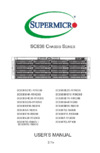
Reset:• The reset button is used to reboot the system.
4-3 Control Panel LEDs
The control panel located on the front of the SC523 chassis has ve LEDs. These
LEDs provide you with critical information related to different parts of the system.
This section explains what each LED indicates when illuminated and any corrective
action you may need to take.
Power Failure:• When this LED ashes, it indicates a power failure in the power
supply
Overheat/Fan Fail •
When Flashing: This LED indicates a fan failure.
When Continuously On (not ashing). This LED indicates an overheat con-
dition caused by cables obstructing the airow in the system or the ambient
room temperature being too warm. To correct this condition, do the following:
Check the Following
Check the routing of the cables and move any cables that restrict the airow.1.
Conrm that all fans are operating normally.2.
Verify that the heatsinks are installed properly.3.
!
Содержание
- User s manual p.1
- Release date august 9 2011 p.2
- Printed in the united states of america p.2
- Manual revision 1 a p.2
- Warning handling of lead solder materials used in this product may expose you to lead a chemical known to the state of california to cause birth defects and other reproductive harm p.2
- Sc523 chassis manual p.2
- Preface p.3
- Chapter 6 rack installation p.4
- Manual organization p.4
- Chapter 5 chassis setup and maintenance p.4
- Chapter 4 system interface p.4
- Chapter 3 chassis components p.4
- Chapter 2 system safety p.4
- Chapter 1 introduction p.4
- Table of contents p.6
- Chapter 5 chassis setup and maintenance p.6
- Chapter 4 system interface p.6
- Chapter 3 chassis components p.6
- Chapter 2 system safety p.6
- Chapter 1 introduction p.6
- Chapter 6 rack installation p.7
- Appendix b sc523 power supply specifications p.7
- Appendix a sc523 chassis cables p.7
- Part numbers p.9
- Introduction p.9
- Chapter 1 p.9
- 2 shipping list p.9
- 1 overview p.9
- 3 contacting supermicro p.10
- System safety p.11
- Chapter 2 p.11
- 4 electrical safety precautions p.11
- 3 preparing for setup p.11
- 2 warnings and precautions p.11
- 1 overview p.11
- 5 general safety precautions p.13
- 6 system safety p.13
- Power supply p.15
- Mounting rails p.15
- Chassis components p.15
- Chassis p.15
- Chapter 3 p.15
- 2 components p.15
- 1 overview p.15
- Air shroud p.16
- 3 where to get replacement components p.16
- System interface p.17
- Chapter 4 p.17
- 2 control panel buttons p.17
- 1 overview p.17
- 3 control panel leds p.18
- 1 overview p.20
- General maintenance p.20
- Chassis setup and maintenance p.20
- Chapter 5 p.20
- 2 installation procedures p.20
- 3 removing the chassis cover p.21
- Perforated tabs p.22
- Air shroud p.22
- 4 removing and installing the air shroud p.22
- 5 removing and installing hard drives p.23
- Mounting screws p.26
- 6 removing and installing the dvd or cd rom p.26
- Installing the i o shield p.27
- I o shield p.27
- 7 installing the motherboard p.27
- Hard drive p.28
- Dvd rom cd rom floppy drive p.28
- Permanent and optional standoffs p.28
- Motherboard installation p.28
- M b standoffs p.28
- Pci slot setup p.30
- Pci slot cover p.30
- Expansion card slots p.30
- Installation complete p.32
- 8 checking the airflow in the system p.32
- System fans p.33
- 9 system fans p.33
- Power supply replacement p.34
- 10 removing and instaling the power supply p.34
- Power supply bracket screws p.35
- Power supply bracket p.35
- Mounting screws p.35
- Mounting screws p.36
- Power supply bracket screws p.36
- Power supply bracket p.36
- Rack installation p.38
- Choosing a setup location p.38
- Chapter 6 p.38
- 3 preparing for setup p.38
- 2 unpacking the system p.38
- 1 overview p.38
- Warnings and precautions p.39
- Rack precautions p.39
- Reliable ground p.40
- Reduced airflow p.40
- Rack mounting considerations p.40
- Mechanical loading p.40
- Circuit overloading p.40
- Ambient operating temperature p.40
- Rail brackets p.41
- Identifying the sections of the rails p.41
- 4 rack mounting instructions p.41
- Installing the chassis into a rack p.44
- Installing the server into a telco rack p.46
- Sc523 chassis cables p.47
- Appendix a p.47
- A 1 overview p.47
- Alternate sas sata cables p.48
- A 3 compatible cables p.48
- Front panel to the motherboard p.49
- Extending power cables p.49
- M b standoffs p.50
- Hard drive p.50
- Dvd rom cd rom floppy drive p.50
- A 5 chassis screws p.50
- The accessory box includes all the screws needed to set up your chassis this p.50
- Section include descriptions of the most common screws used your chassis may not require all the parts listed p.50
- Sc523 chassis manual p.50
- Sc523 power supply specifications p.51
- Appendix b p.51
Похожие устройства
-
 Supermicro CSE-825TQ-R740LPBИнструкция по эксплуатации
 -
 Supermicro CSE-815TQ-600CBИнструкция по эксплуатации
 -
 Supermicro CSE-732D2-500BИнструкция по эксплуатации
 -
 Supermicro cse-745btq-r1k28b-sqИнструкция по эксплуатации
 -
 Supermicro cse-733tq-500bИнструкция по эксплуатации
 -
Supermicro cse-733t-500bИнструкция по эксплуатации
-
 Supermicro cse-826be16-r1k28lpbИнструкция по эксплуатации
 -
 Supermicro cse-732i-865bИнструкция по эксплуатации
 -
Supermicro cse-732i-500bИнструкция по эксплуатации
-
 Supermicro cse-743tq-865b-sqИнструкция по эксплуатации
 -
 Supermicro cse-835tq-r800bИнструкция по эксплуатации
 -
 Supermicro cse-836be16-r920Инструкция по эксплуатации
Узнайте, как использовать кнопку сброса и расшифровать индикаторы на панели управления шасси. Получите советы по устранению неполадок с питанием и перегревом.