![Supermicro CSE-523L-410B — установка сервера в телекоммуникационный шкаф: пошаговое руководство [46/52]](/img/pdf.png)
Supermicro CSE-523L-410B — установка сервера в телекоммуникационный шкаф: пошаговое руководство [46/52]
![Supermicro CSE-523L-410B [46/52] Installing the server into a telco rack](/views2/1190283/page46/bg2e.png)
6-9
Chapter 6: Rack Installation
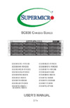
Figure 6-6: Mounting the Chassis onto an Open (Telco) Rack
Installing the Server into a Telco Rack
Installing the chassis into a Telco type rack
Use two L-brackets on either side of the chassis (four total). Determine how 1.
far the server will extend out the front of the rack. Larger chassis should be
positioned to balance the weight between the front and back of the rack. If a
bezel is included on your chassis, remove it.
Attach the two front brackets to each side of the chassis, and then add the 2.
two rear brackets, positioning them with just enough space to accommodate
the width of the rack.
Complete the installation by sliding the chassis into the rack and tightening 3.
the brackets.
L-Brackets
L-Brackets
Содержание
- User s manual p.1
- Release date august 9 2011 p.2
- Printed in the united states of america p.2
- Manual revision 1 a p.2
- Warning handling of lead solder materials used in this product may expose you to lead a chemical known to the state of california to cause birth defects and other reproductive harm p.2
- Sc523 chassis manual p.2
- Preface p.3
- Chapter 6 rack installation p.4
- Manual organization p.4
- Chapter 5 chassis setup and maintenance p.4
- Chapter 4 system interface p.4
- Chapter 3 chassis components p.4
- Chapter 2 system safety p.4
- Chapter 1 introduction p.4
- Table of contents p.6
- Chapter 5 chassis setup and maintenance p.6
- Chapter 4 system interface p.6
- Chapter 3 chassis components p.6
- Chapter 2 system safety p.6
- Chapter 1 introduction p.6
- Chapter 6 rack installation p.7
- Appendix b sc523 power supply specifications p.7
- Appendix a sc523 chassis cables p.7
- Part numbers p.9
- Introduction p.9
- Chapter 1 p.9
- 2 shipping list p.9
- 1 overview p.9
- 3 contacting supermicro p.10
- System safety p.11
- Chapter 2 p.11
- 4 electrical safety precautions p.11
- 3 preparing for setup p.11
- 2 warnings and precautions p.11
- 1 overview p.11
- 5 general safety precautions p.13
- 6 system safety p.13
- Power supply p.15
- Mounting rails p.15
- Chassis components p.15
- Chassis p.15
- Chapter 3 p.15
- 2 components p.15
- 1 overview p.15
- Air shroud p.16
- 3 where to get replacement components p.16
- System interface p.17
- Chapter 4 p.17
- 2 control panel buttons p.17
- 1 overview p.17
- 3 control panel leds p.18
- 1 overview p.20
- General maintenance p.20
- Chassis setup and maintenance p.20
- Chapter 5 p.20
- 2 installation procedures p.20
- 3 removing the chassis cover p.21
- Perforated tabs p.22
- Air shroud p.22
- 4 removing and installing the air shroud p.22
- 5 removing and installing hard drives p.23
- Mounting screws p.26
- 6 removing and installing the dvd or cd rom p.26
- Installing the i o shield p.27
- I o shield p.27
- 7 installing the motherboard p.27
- Hard drive p.28
- Dvd rom cd rom floppy drive p.28
- Permanent and optional standoffs p.28
- Motherboard installation p.28
- M b standoffs p.28
- Pci slot setup p.30
- Pci slot cover p.30
- Expansion card slots p.30
- Installation complete p.32
- 8 checking the airflow in the system p.32
- System fans p.33
- 9 system fans p.33
- Power supply replacement p.34
- 10 removing and instaling the power supply p.34
- Power supply bracket screws p.35
- Power supply bracket p.35
- Mounting screws p.35
- Mounting screws p.36
- Power supply bracket screws p.36
- Power supply bracket p.36
- Rack installation p.38
- Choosing a setup location p.38
- Chapter 6 p.38
- 3 preparing for setup p.38
- 2 unpacking the system p.38
- 1 overview p.38
- Warnings and precautions p.39
- Rack precautions p.39
- Reliable ground p.40
- Reduced airflow p.40
- Rack mounting considerations p.40
- Mechanical loading p.40
- Circuit overloading p.40
- Ambient operating temperature p.40
- Rail brackets p.41
- Identifying the sections of the rails p.41
- 4 rack mounting instructions p.41
- Installing the chassis into a rack p.44
- Installing the server into a telco rack p.46
- Sc523 chassis cables p.47
- Appendix a p.47
- A 1 overview p.47
- Alternate sas sata cables p.48
- A 3 compatible cables p.48
- Front panel to the motherboard p.49
- Extending power cables p.49
- M b standoffs p.50
- Hard drive p.50
- Dvd rom cd rom floppy drive p.50
- A 5 chassis screws p.50
- The accessory box includes all the screws needed to set up your chassis this p.50
- Section include descriptions of the most common screws used your chassis may not require all the parts listed p.50
- Sc523 chassis manual p.50
- Sc523 power supply specifications p.51
- Appendix b p.51
Похожие устройства
-
 Supermicro CSE-825TQ-R740LPBИнструкция по эксплуатации
 -
 Supermicro CSE-815TQ-600CBИнструкция по эксплуатации
 -
 Supermicro CSE-732D2-500BИнструкция по эксплуатации
 -
 Supermicro cse-745btq-r1k28b-sqИнструкция по эксплуатации
 -
 Supermicro cse-733tq-500bИнструкция по эксплуатации
 -
Supermicro cse-733t-500bИнструкция по эксплуатации
-
 Supermicro cse-826be16-r1k28lpbИнструкция по эксплуатации
 -
 Supermicro cse-732i-865bИнструкция по эксплуатации
 -
Supermicro cse-732i-500bИнструкция по эксплуатации
-
 Supermicro cse-743tq-865b-sqИнструкция по эксплуатации
 -
 Supermicro cse-835tq-r800bИнструкция по эксплуатации
 -
 Supermicro cse-836be16-r920Инструкция по эксплуатации
Узнайте, как правильно установить сервер в телекоммуникационный шкаф с помощью L-образных кронштейнов. Пошаговые инструкции для надежной установки.