![Hotpoint-Ariston C3V M57 W RU [2/24] Installation](/img/pdf.png)
Hotpoint-Ariston C3V M57 W RU [2/24] Installation
Содержание
- C3vm5r 1
- Care and maintenance 11 1
- Contents 1
- Cooker and oven 1
- Description of the appliance 4 1
- Installation 2 3 1
- Operating instructions 1
- Precautions and tips 10 1
- Start up and use 5 8 1
- Using the glass ceramic hob 9 1
- Â ariston 1
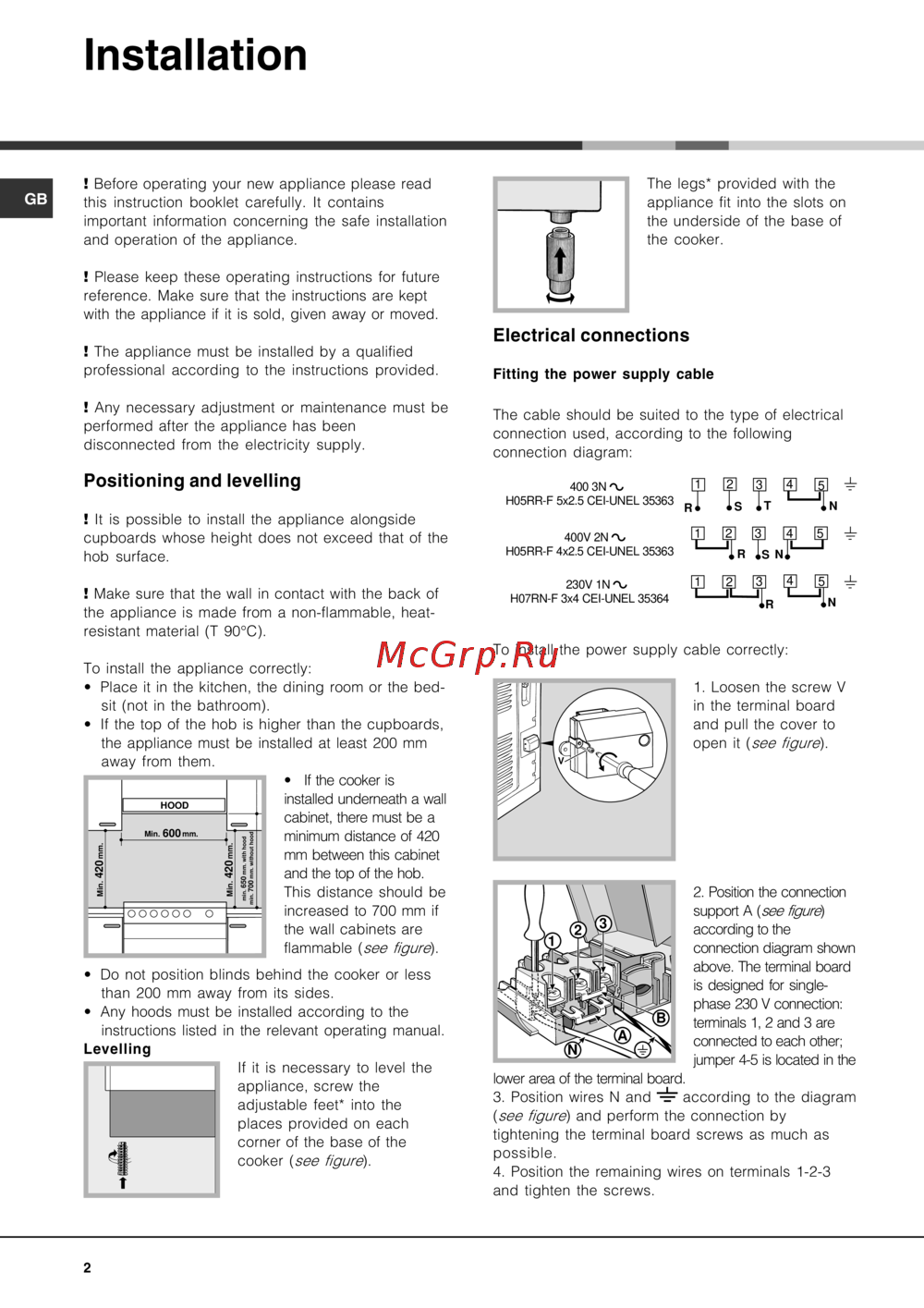
- Installation 2
- Ariston 3
- Adjustable 4
- Button 4
- Control panel 4
- Description of the appliance 4
- For the sliding racks position 5 position 4 position 3 position 2 position 1 4
- Hotplate knobs 4
- Indicator light 4
- O sc sc o 4
- Overall view 4
- Start up and use 5
- Starting the oven 5
- Â ariston 5
- Cooking modes 6
- Electronic timer 6
- Ariston 7
- Cooking 8
- Cooking modes foods weight in kg 8
- Double grill 8
- Fan assisted 8
- Fan assisted double grill 8
- Grilled chicken 8
- Minutes 8
- Oven cooking advice table 8
- Position 8
- Preheating time 8
- Recommended 8
- Static 8
- Temperature 8
- With multi spit rotisserie 8
- With the rotisserie 8
- Cooking zones 9
- Switching the cooking zones on and off 9
- Using the glass ceramic hob 9
- Â ariston 9
- Disposal 10
- General safety 10
- Precautions and tips 10
- Respecting and conserving the environment 10
- Assistance 11
- Care and maintenance 11
- Cleaning the glass ceramic hob 11
- Cleaning the oven 11
- Replacing the oven light bulb 11
- Switching the appliance off 11
- Â ariston 11
- 1 ariston 12
- C3vm5r 12
- Включение и эксплуатация 16 19 12
- Кухонная плита с духовым шкафом 12
- Монтаж 13 14 12
- Описание изделия 15 12
- Предосторожности и рекомендации 21 12
- Руководство по эксплуатации 12
- Содержание 12
- Стеклокерамическая варочная панель 20 12
- Техническое обслуживание и уход 22 12
- Й ariston 13
- Оооооо о 13
- Подсоединение 13
- Расположение и нивелировка 13
- Установка 13
- Электрическое 13
- Й ariston 15
- Общий вид 15
- Описание изделия 15
- Панель управления 15
- Включение духового шкафа 16
- Включение и эксплуатация 16
- Й ariston 17
- Программы приготовления 17
- Электронный таймер 17
- Регуляция громкости звукового сигнала 18
- Й ariston 19
- Таблица приготовления в духовом шкафу 19
- Включение и выключение нагревательных зон 20
- Нагревательные зоны 20
- Электрическая варочная панель 20
- Й ariston 21
- Общие требования к безопасности 21
- Предосторожности и рекомендации 21
- Утилизация 21
- Экономия электроэнергии и охрана окружающей среды 21
- Замена лампочки в духовом шкафу 22
- Отключение электропитания 22
- Техническое обслуживание 22
- Техническое обслуживание и уход 22
- Чистка духового шкафа 22
- Чистка стеклокерамическои варочной панели 22
Похожие устройства
- Beko WKB 50621 PT Инструкция по эксплуатации
- Inter-M MA-212 Инструкция по эксплуатации
- Bosch PSB 700 RE 0603386465 Инструкция по эксплуатации
- Casio CTK-810 Инструкция по эксплуатации
- Beko WKL 13500 D Инструкция по эксплуатации
- Gorenje GN 51101 IW Инструкция по эксплуатации
- Inter-M PA-920 Инструкция по эксплуатации
- Sturm ID2150I Инструкция по эксплуатации
- Casio CTK-900 Инструкция по эксплуатации
- Beko WKB 61021 PTMA Инструкция по эксплуатации
- Gorenje EGI 440 E Инструкция по эксплуатации
- Mystery MMD-674U Инструкция по эксплуатации
- Bosch GSB 22-2 RCE 0.601.146.761 Инструкция по эксплуатации
- Inter-M PA-935A Инструкция по эксплуатации
- Gorenje GI 62378 BW Инструкция по эксплуатации
- Casio LK-100 Инструкция по эксплуатации
- Beko WKB 61041 PTMC Инструкция по эксплуатации
- Mystery MMD-684U Инструкция по эксплуатации
- Inter-M PA-1000B Инструкция по эксплуатации
- Bosch PSB 650 RA 0603126320 Инструкция по эксплуатации
Installation GB Before operating your new appliance please read this instruction booklet carefully It contains important information concerning the safe installation and operation of the appliance The legs provided with the appliance fit into the slots on the underside of the base of the cooker Please keep these operating instructions for future reference Make sure that the instructions are kept with the appliance if it is sold given away or moved Electrical connections The appliance must be installed by a qualified professional according to the instructions provided Any necessary adjustment or maintenance must be performed after the appliance has been disconnected from the electricity supply Positioning and levelling It is possible to install the appliance alongside cupboards whose height does not exceed that of the hob surface Make sure that the wall in contact with the back of the appliance is made from a non flammable heatresistant material T 90 C Fitting the power supply cable The cable should be suited to the type of electrical connection used according to the following connection diagram 400 3N V H05RR F 5x2 5 CEI UNEL 35363 RT Ï 400V 2N V H05RR F 4x2 5 CEI UNEL 35363 230V 1N V H07RN F 3x4 CEI UNEL 35364 To install the power supply cable correctly To install the appliance correctly Place it in the kitchen the dining room or the bed sit not in the bathroom If the top of the hob is higher than the cupboards the appliance must be installed at least 200 mm If the cooker is installed underneath a wall cabinet there must be a minimum distance of 420 mm between this cabinet and the top of the hob This distance should be increased to 700 mm if the wall cabinets are flammable see figure Do not position blinds behind the cooker or less than 200 mm away from its sides Any hoods must be installed according to the instructions listed in the relevant operating manual If it is necessary to level the appliance screw the adjustable feet into the places provided on each corner of the base of the cooker see figure 2 1 Loosen the screw V in the terminal board and pull the cover to open it see figure 2 Position the connection support A see figuré according to the connection diagram shown above The terminal board is designed for single phase 230 V connection terminals 1 2 and 3 are connected to each other jumper 4 5 is located in the lower area of the terminal board 3 Position wires N and according to the diagram see figure and perform the connection by tightening the terminal board screws as much as possible 4 Position the remaining wires on terminals 1 2 3 and tighten the screws