
Daikin VAM500FJVE Сервис мануал онлайн
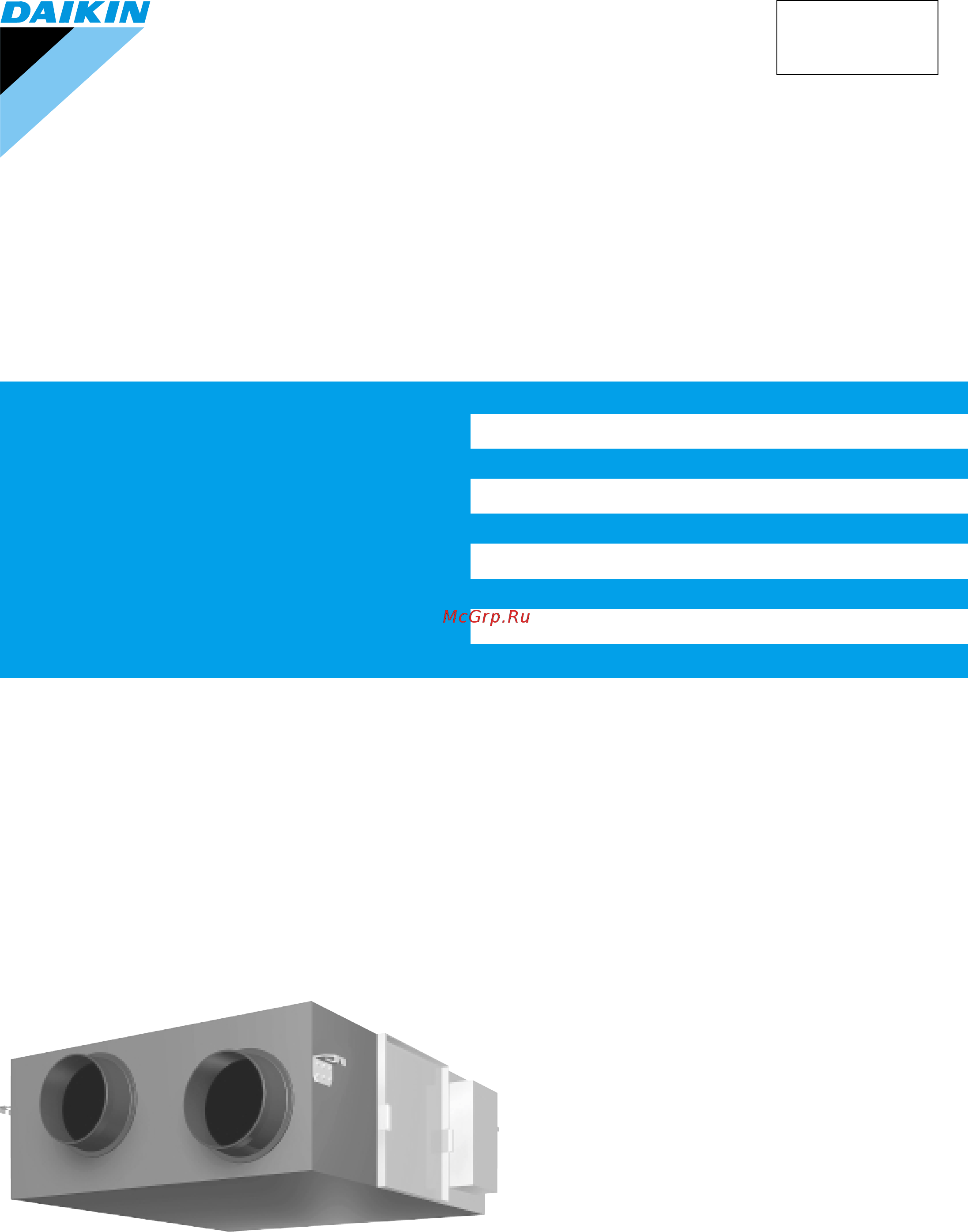
Service
Manual
SiE00-01
Heat Recovery Ventilation
[Applied Models]
VAM 150FJVE
VAM 250FJVE
VAM 350FJVE
VAM 500FJVE
VAM 650FJVE
VAM 800FJVE
VAM1000FJVE
VAM1500FJVE
VAM2000FJVE
Содержание
- Heat recovery ventilation 1
- Manual 1
- Service 1
- Sie00 01 1
- Heat recovery ventilation 2
- Circuit operations 0 3
- Control functions 2 3
- General constructions 3
- Introduction v 3
- Maintenance 6 3
- Operation 0 3
- Part 1 general constructions 3
- Part 2 product specification 3
- Part 3 operation 3
- Part 4 maintenance 5 3
- Part 5 control functions 1 3
- Part 6 circuit operations 9 3
- Part 7 troubleshooting 3 3
- Product specification 3
- Troubleshooting 4 3
- Appendix 6 4
- Drawings flow charts v 4
- Index i 4
- Part 8 supplementary explanation 3 4
- Part 9 appendix 5 4
- Supplementary explanation 4 4
- Cautions and warnings 6
- Introduction 6
- Safety cautions 6
- Sie00 01 introduction 6
- Cautions in operation and maintenance 7
- Icons are used to attract the attention of the reader to specific information the meaning of each icon is described in the table below 9
- Introduction sie00 01 9
- Using icons 9
- Using icons list 9
- Explanation 2 10
- General constructions 10
- Part 1 general constructions 10
- Explanation 11
- General constructions 11
- General constructions sie00 01 11
- Vam150fjve vam250fjve vam350fjve vam500fjve vam650fjve vam800fjve vam1000fjve 11
- General constructions 3 12
- Sie00 01 general constructions 12
- Vam1500fjve vam2000fjve 12
- Part 2 14
- Part 2 product specification 14
- Product specification 14
- Specification 6 14
- Product specification 15
- Product specification sie00 01 15
- Specification 15
- 50 60hz 16
- Product specification 7 16
- Sie00 01 product specification 16
- Test conditions are as follows 16
- 50 60hz 17
- Product specification 17
- Product specification sie00 01 17
- Test conditions are as follows 17
- Operation 0 18
- Part 3 operation 18
- Explanation for systems 19
- Operation 19
- Operation sie00 01 19
- Operation 11 20
- Operation for individual system 20
- Operation with the remote control for air conditioning operation hrv units brc301b61 20
- Remote controller for hrv brc301b61 20
- Sie00 01 operation 20
- Operation 21
- Operation sie00 01 21
- Independent operation of the hrv unit using the centralized controller dcs302b61 22
- Operating the hrv unit using the remote controller of the vrv system air conditioner 22
- Operation 13 22
- Remote controller for vrv brc1a61 62 22
- Sie00 01 operation 22
- Maintenance 6 24
- Part 4 maintenance 24
- Maintenance 25
- Maintenance for the air filter 25
- Maintenance sie00 01 25
- Vam150 25
- If the air filter is washed remove water completely and allow to dry air filter for 20 to 30 minutes in the shade when dried completely install the air filter back in place 26
- Maintenance 17 26
- Sie00 01 maintenance 26
- Take out the heat exchange elements from the unit body 26
- To clean the air filter lightly pat it with hand or remove dust with a vacuum cleaner if excessively dirty wash it in water 26
- Vam150 26
- Maintenance 27
- Maintenance sie00 01 27
- Maintenance 19 28
- Maintenance for the heat exchange element 28
- Sie00 01 maintenance 28
- Control functions 2 30
- Part 5 control functions 30
- Control functions 31
- Control functions sie00 01 31
- List of control functions 31
- Note note 1 requires optional humidifier and optional printed circuit board krp50 2 wiring adapter for remote contact 31
- Control functions 23 32
- Controls ventilation fan motors supply and exhaust air fans and damper motor 1 normal operation operation chart 32
- Direct duct connection with air conditioner operation chart 32
- Explanation of individual functions 32
- Note direct duct connection setting can be made in vrv system or using field setting mode of hrv lcd remote controller 32
- Sie00 01 control functions 32
- Ventilation operation control 32
- Control functions 33
- Control functions sie00 01 33
- Note operation standby indication is displayed only on lcd remote controller of heat recovery ventilation unit 33
- Pre cool pre heat 33
- Pre cool pre heat operations require the following conditions 1 system pre heat operation is possible only in air conditioner linked system 1 group 2 group link check the system first 2 heat recovery ventilation setting set preheat on off to on pre cool pre heat on off setting can be made in air conditioner or using field setting mode of lcd remote controller of heat recovery ventilation unit pre cool time can be set between 30 and 60 min and pre heat time can be set between 30 and 150 min 3 others a heat recovery ventilation unit must be in non operating condition for two consecutive hours or more prior to pre cool pre heat operation b temperature control mode of the air conditioner must be set to cool heat or dry 33
- Air conditioner link operation 34
- Cold area mode 34
- Control functions 25 34
- Link system enables simultaneous on off operation of heat recovery ventilation unit and air conditioner vrv system skyair 1 1 group link control allows simultaneous on off from remote controller for air conditioner allows independent operation of heat recovery ventilation unit from vrv system remote controller during interim periods not possible when direct duct connection is used on off operation is not possible from lcd remote controller of heat recovery ventilation unit 34
- Note cold area mode can set using remote controller for air conditioner or field setting mode of lcd remoter controller of heat recovery ventilation unit 34
- Operation chart in heating operation only 34
- Sie00 01 control functions 34
- Stops or lowers ventilation airflow during defrosting operation and compressor non operating condition when equipment in heating mode thus reducing heating load and cold air draft 34
- Control functions 35
- Control functions sie00 01 35
- Field setting 35
- Field setting service mode 35
- Field setting used for initial setting of heat recoveryw ventilation unit 2 service mode used for confirmation of unit nos in the group and reallocation of unit nos 35
- Link control of 2 or more groups zone link heat recovery ventilation unit can be operated when one or more air conditioners are operating allows independent operation of heat recovery ventilation unit from vrv system remote controller during interim periods direct duct connection is not allowed in this system on off operation is not possible from lcd remote controller of heat recovery ventilation unit 35
- List of field setting and service mode 35
- Note with super wiring units of different outdoor systems can be linked in operation 35
- Refer to p54 35
- Refer to p55 35
- Caution 1 the setting positions are set at 01 at the factory the ventilation air flow however is set at 05 medium in the hrv unit when lower or higher setting is desired change the setting after installation 36
- Control functions 27 36
- Field setting 36
- Note 1 all the setting can be made by the remote controller for vrv and hrv unit the setting of mode no 19 29 and 40 can be made only by the remote controller for vrv unit the mode no 30 is used for the individual setting such as the calculation of power bill etc 2 the mode no in is used for making individual setting of each unit 3 group number setting for centralized controller 1 mode no 00 group controller 2 mode no 30 individual controller regarding the setting procedure refer to the section group number setting for centralized control in the operating manual of either the on off controller or the central controller 36
- Refer to e d installation manual 36
- Refer to operation manual for remote controller of air conditioner 36
- Refer to p54 36
- Refer to p56 36
- Refer to p57 36
- Service 36
- Sie00 01 control functions 36
- Control functions 37
- Control functions sie00 01 37
- Function of main connection terminal 37
- Layout of switches on printed circuit board 37
- P2 p1 f1 f2 j1 j2 jc 37
- Printed circuit board 37
- Circuit operations 0 38
- Part 6 circuit operations 38
- Circuit configuration 39
- Circuit operations 39
- Circuit operations sie00 01 39
- Circuit functions 40
- Circuit operations 31 40
- Sie00 01 circuit operations 40
- Part 7 troubleshooting 42
- Troubleshooting 4 42
- Error code indication 43
- In case of the mulfunction with the shaded error code the unit still operates however be sure to have it inspected and repaired and as soon as possible 43
- List of malfunction codes displayed by lcd remote controller 43
- Troubleshooting 43
- Troubleshooting sie00 01 43
- When an abnormality is generated take necessary measures by referring to displayed error code after the cause of abnormality is removed operate equipment and check proper functioning 43
- Overall alarm 44
- Error detection method 45
- Error generating conditions 45
- Led indication 45
- Overall malfunction 45
- Possible causes 45
- Remote controller lcd display 45
- Troubleshooting 45
- Troubleshooting sie00 01 45
- Indoor air thermistor error 46
- Outdoor air thermistor error 47
- Damper system error alarm 48
- Damper system error alarm 49
- Error detection method 49
- Error generating conditions 49
- Led indication 49
- Possible causes 49
- Remote controller lcd display 49
- Troubleshooting 49
- Troubleshooting sie00 01 49
- Dedicated lcd remote controller 50
- Dedicated remote controller 50
- Error detection method 50
- Error generating conditions 50
- Main unit pcb 50
- Master slave setting of remote controller remote controller pcb assembly error main unit pcb assembly error 50
- Possible causes 50
- Remains on remote controller display 50
- Remote control setting error eg one remote controller set to sub and a second remote controller set to main main or sub sub 50
- Sie00 01 troubleshooting 50
- Troubleshooting 50
- Troubleshooting 41 50
- Data transmission error between lcd remote controller and main unit 51
- Error detection method 51
- Error generating conditions 51
- Led indication 51
- Possible causes 51
- Remote controller lcd display 51
- Troubleshooting 51
- Troubleshooting sie00 01 51
- Uuuu555 51
- Data transmission error lcd remote controller 52
- Error detection method 52
- Error generating conditions 52
- Led indication 52
- Possible causes 52
- Remote controller lcd display 52
- Sie00 01 troubleshooting 52
- Troubleshooting 52
- Troubleshooting 43 52
- Uuuu555 52
- Data transmission error between lcd master remote controller and slave remote controller 53
- Error detection method 53
- Error generating conditions 53
- Led indication 53
- Possible causes 53
- Remote controller lcd display 53
- Troubleshooting 53
- Troubleshooting sie00 01 53
- Uuuu888 53
- Error detection method 54
- Error generating conditions 54
- Field setting error 54
- Led indication 54
- Possible causes 54
- Remote controller lcd display 54
- Sie00 01 troubleshooting 54
- Troubleshooting 54
- Troubleshooting 45 54
- Uuuuaaa 54
- Overlapping central control address 55
- Uuuuccc 55
- Check microcomputer operation monitor 56
- Error detection method 56
- Error generating conditions 56
- Fuse excess current power transformer noise main unit pcb 56
- Main unit pcb 56
- Main unit pcb assembly 56
- Possible causes 56
- Sie00 01 troubleshooting 56
- Troubleshooting 56
- Troubleshooting 47 56
- When main unit pcb assembly does not operate when communication circuit errors 56
- Check 1 2 3 refer to page 49 57
- Check to see if remote controller displays indication 57
- Dedicated lcd remote controller 57
- Error detection method 57
- Error generating conditions 57
- Error on communication wire noise etc other than malfunction faulty remote control pcb 57
- Possible causes 57
- Troubleshooting 57
- Troubleshooting sie00 01 57
- When main unit pcb assembly does not operate when communication circuit errors 57
- When no indication is displayed on remote controller 57
- Check 1 58
- Check 2 58
- Check 3 58
- Dedicated lcd remote controller option 58
- How to check 58
- Lcd remote controller 58
- Main unit pcb 58
- Remote controller for heat recovery ventilation 58
- Sie00 01 troubleshooting 58
- Troubleshooting 49 58
- Deterioration of thermistor 59
- Error detection method 59
- Error generating conditions 59
- Faulty thermistor broken wire faulty control pcb faulty contact in connector 59
- If measured value deviates significantly from above values thermistor is faulty use tester to check resistance 59
- Note refer to the thermistor temperature resistance conversion table when measuring resistance 59
- Possible causes 59
- Remove thermistor and check resistance with tester 59
- Thermistor 59
- Thermistor temperature resistance conversion table 59
- Troubleshooting 59
- Troubleshooting sie00 01 59
- Check resistance and voltage with tester and insulation resistance with megger 60
- Deterioration of transformer 60
- Error detection method 60
- Error generating conditions 60
- Overcurrent by surging etc deterioration of transformer 60
- Possible causes 60
- Power transformer 60
- Resistance of primary side of transformer approx 140 ω resistance of secondary side of transformer approx 1 ω voltage at secondary side of transformer when rated voltage is applied to primary side approx 26 vac insulation resistance between primary side of transformer and case 100 m ω or higher insulation resistance between secondary side of transformer and case 100 m ω or higher insulation resistance between primary side and secondary side of transformer 100 m ω or higher 60
- Sie00 01 troubleshooting 60
- Troubleshooting 60
- Troubleshooting 51 60
- Check damper motor and limit switch when damper motor does not operate 61
- Check resistance and voltage damper motor 61
- Damper motor 61
- Deterioration of damper motor deterioration of limit switch 61
- Error detection method 61
- Error generating conditions 61
- Possible causes 61
- Troubleshooting 61
- Troubleshooting sie00 01 61
- Field setting service mode operation 54 62
- Part 8 supplementary explanation 62
- Supplementary explanation 4 62
- Field setting 63
- Field setting service mode operation 63
- Supplementary explanation 63
- Centralized control group no setting mode no 00 setting of individual no mode no 30 64
- Sie00 01 supplementary explanation 64
- Supplementary explanation 55 64
- Service mode operation 65
- Supplementary explanation 65
- Supplementary explanation sie00 01 65
- Turn on the forced fan mode no 3 65
- Sie00 01 supplementary explanation 66
- Supplementary explanation 57 66
- Unit no reallocation mode no 5 66
- Connection type operation changeover control display 67
- Cooling heating selection privilege off display 67
- Cooling heating selection privilege on no display 67
- Display on off condition by connection type and cooling heating selection privilege 67
- Example of operation changeover control display 67
- For group control of systems containing heat recovery ventilation units and air conditioners vrv system remote controllers of air conditioners are connected with remote controllers of new heat recovery ventilation units in such system both remote controllers display operation changeover control according to the on off of cooling heating selection privilege the following diagram shows the display on off condition determined by the unit combination 67
- Heat recovery ventilation unit air conditioner vrv system cooling heating selection privilege not set flashing note 1 67
- Heat recovery ventilation unit only no display 67
- Note note 1 only master remote controller can display flashing operation changeover control when cooling heating selection privilege is not set 67
- Operation changeover control 67
- Supplementary explanation 67
- Supplementary explanation sie00 01 67
- Field setting 68
- List of field setting mode nos 68
- Sie00 01 supplementary explanation 68
- Supplementary explanation 59 68
- The following shows the procedure for field setting using remote controller of new heat recovery ventilation unit 68
- Lcd and operation panel reference information 69
- Inspection 70
- Inspection indication flashes 70
- Inspection operation is shown below 70
- Sie00 01 supplementary explanation 70
- Supplementary explanation 61 70
- Ventilation volume freshup 70
- Ventilation volume freshup setting changes as follows 70
- Centralized control group no setting mode no 00 71
- Centralized control group no setting mode no 30 71
- Field setting 71
- Procedure for entering individual settings mode no 44 71
- Supplementary explanation 71
- Supplementary explanation sie00 01 71
- Individual settings 72
- Sie00 01 supplementary explanation 72
- Supplementary explanation 63 72
- Appendix 6 74
- Part 9 appendix 74
- Wiring diagram 66 74
- Appendix 75
- Wiring diagram 75
- Drawings flow charts 82
- Daikin products are distributed by 84
- Head office umeda center bldg 4 12 nakazaki nishi 2 chome kita ku osaka 530 japan 84
- Specifications subject to change without notice 84
- Zandvoordestraat 300 b 8400 oostende belgium 84
Похожие устройства
- Daikin VAM350FJVE Сервис мануал
- Daikin VAM650FJVE Инструкция по эксплуатации
- Daikin VAM650FJVE Сервис мануал
- Daikin VAM800FJVE Инструкция по эксплуатации
- Daikin VAM800FJVE Сервис мануал
- Daikin VAM1000FJVE Инструкция по эксплуатации
- Daikin VAM1000FJVE Сервис мануал
- Daikin VAM1500FJVE Инструкция по эксплуатации
- Daikin VAM1500FJVE Сервис мануал
- Daikin VAM2000FJVE Инструкция по эксплуатации
- Daikin VAM2000FJVE Сервис мануал
- Daikin VAM150FA7VE Инструкция по монтажу
- Daikin VAM150FA7VE Технические данные
- Daikin VAM250FA7VE Инструкция по монтажу
- Daikin VAM250FA7VE Технические данные
- Daikin VAM350FA7VE Инструкция по монтажу
- Daikin VAM350FA7VE Технические данные
- Daikin VAM500FA7VE Инструкция по монтажу
- Daikin VAM500FA7VE Технические данные
- Daikin VAM650FA7VE Инструкция по монтажу