
Daikin FTKS20CVMB Сервис мануал онлайн
Inverter Pair
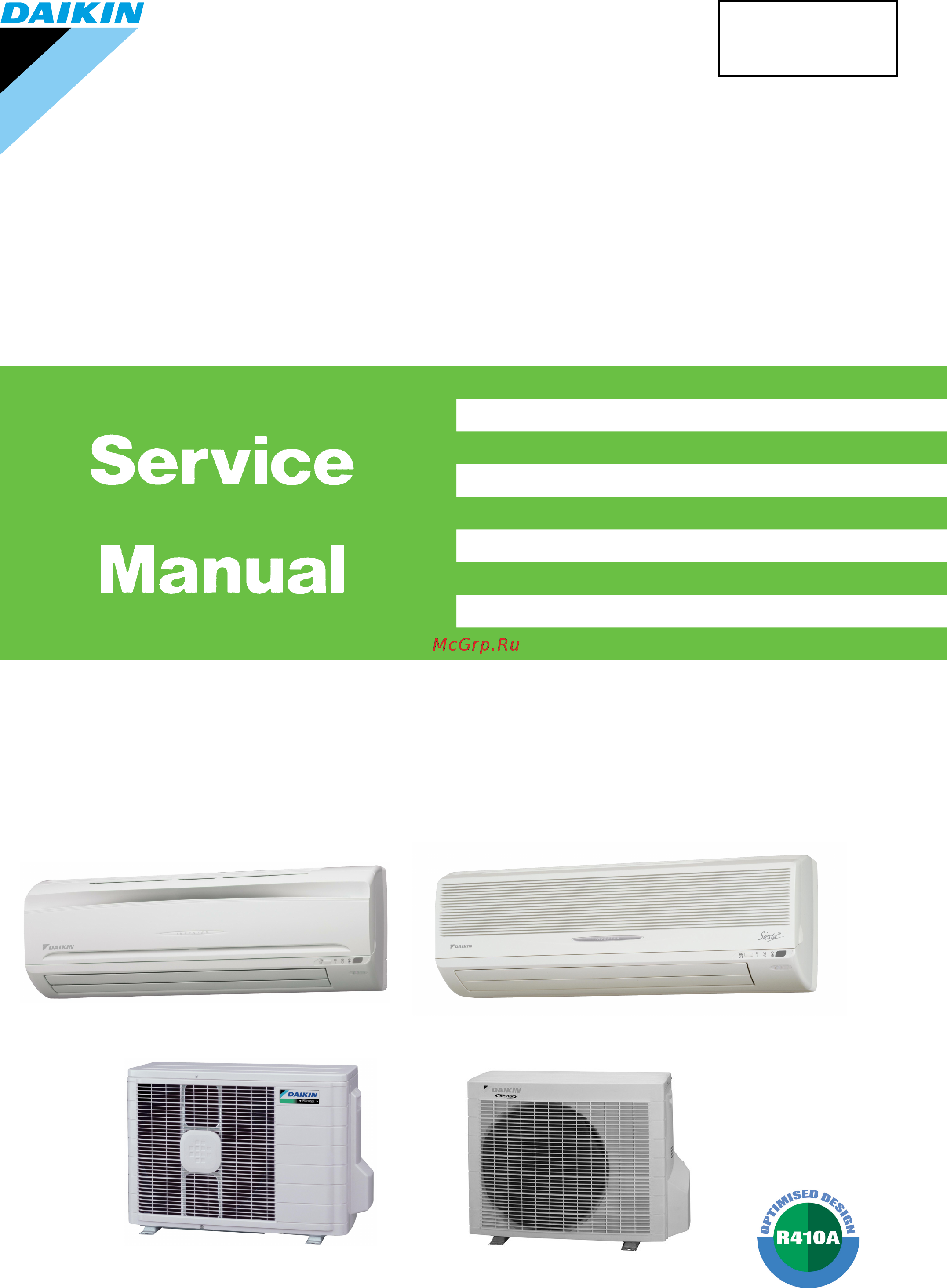
Wall Mounted Type C-Series
[Applied Models]
z
zz
zInverter Pair : Cooling Only
z
zz
zInverter Pair : Heat Pump
SiBE04-401
Содержание
- Inverter pair 1
- Sibe04 401 1
- Wall mounted type c series 1
- Inverter pair inverter pair inverter pair inverter pair c series c series c series c series 2
- Table of contents 2
- Control specification 4 3
- Function of main structural parts 2 3
- Introduction v 3
- List of functions 3
- Main functions 0 3
- Part 1 list of functions 3
- Part 2 specifications 3
- Part 3 printed circuit board connector wiring diagram 3 3
- Part 4 function and control 9 3
- Printed circuit board connector wiring diagram 4 3
- Specifications 3
- Caution for diagnosis 0 2 problem symptoms and measures 1 3 service check function 2 4 troubleshooting 5 4
- Check 24 4
- Part 5 system configuration 9 4
- Part 6 service diagnosis 9 4
- System configuration 0 2 instruction 1 4
- Drawings flow charts v 5
- Index i 5
- Indoor unit 34 5
- Others 04 5
- Outdoor unit rk x h c ark x h c r y n c 76 5
- Outdoor unit rk x s c ark x s c 56 5
- Part 7 removal procedure 33 5
- Part 8 others 03 5
- Part 9 appendix 07 5
- Piping diagrams 08 5
- Wiring diagrams 13 5
- Caution in repair 6
- Introduction 6
- Safety cautions 6
- Warning 6
- Cautions regarding products after repair 7
- Warning 7
- Caution 8
- Inspection after repair 8
- Warning 8
- Caution 9
- Icons are used to attract the attention of the reader to specific information the meaning of each icon is described in the table below 9
- Using icons 9
- Using icons list 9
- Warning 9
- Part 1 list of functions 10
- High grade models 11
- Holding functions no functions 11
- List of functions 11
- List of functions sibe04 401 11
- Holding functions no functions 12
- List of functions 3 12
- Sibe04 401 list of functions 12
- Holding functions no functions 13
- List of functions 13
- List of functions sibe04 401 13
- Standard grade models 13
- Holding functions no functions 14
- List of functions 5 14
- Sibe04 401 list of functions 14
- Holding functions no functions 15
- List of functions 15
- List of functions sibe04 401 15
- Non lnverter models 15
- Part 2 specifications 16
- Cooling only 17
- High grade models 17
- Specifications 17
- Specifications sibe04 401 17
- Sibe04 401 specifications 18
- Specifications 9 18
- V 50hz 18
- Specifications 19
- Specifications sibe04 401 19
- Standard grade models 19
- V 50hz 19
- Sibe04 401 specifications 20
- Specifications 11 20
- V 50hz 20
- Non lnverter models 21
- Specifications 21
- Specifications sibe04 401 21
- V 50hz 21
- Heat pump 22
- High grade models 22
- Sibe04 401 specifications 22
- Specifications 13 22
- V 50hz 22
- Specifications 23
- Specifications sibe04 401 23
- V 50hz 23
- Sibe04 401 specifications 24
- Specifications 15 24
- V 50hz 24
- Specifications 25
- Specifications sibe04 401 25
- V 50hz 25
- Sibe04 401 specifications 26
- Specifications 17 26
- Standard grade models 26
- V 50hz 26
- Specifications 27
- Specifications sibe04 401 27
- V 50hz 27
- Sibe04 401 specifications 28
- Specifications 19 28
- V 50hz 28
- Specifications 29
- Specifications sibe04 401 29
- V 50hz 29
- Non lnverter models 30
- Sibe04 401 specifications 30
- Specifications 21 30
- V 50hz 30
- Specifications 31
- Specifications sibe04 401 31
- V 50hz 31
- Part 3 printed circuit board connector wiring diagram 32
- Indoor unit 33
- Printed circuit board connector wiring diagram 33
- Pcb 3 intelligent eye sensor pcb 34
- Pcb detail pcb 1 control pcb pcb 2 signal receiver pcb 34
- Printed circuit board connector wiring diagram 25 34
- Sibe04 401 printed circuit board connector wiring diagram 34
- Outdoor unit rk x s c ark x s c 35
- Pcb 2 filter pcb 36
- Pcb detail pcb 1 control pcb outdoor unit 36
- Printed circuit board connector wiring diagram 27 36
- Sibe04 401 printed circuit board connector wiring diagram 36
- Outdoor unit rk x h c ark x h c r y n c 37
- Control specification 4 38
- Function of main structural parts 2 38
- Main functions 0 38
- Part 4 function and control 38
- Part 4 part 4 part 4 part 4 function and control function and control function and control function and control 38
- Additional control parameters 39
- Drawing of inverter the following drawing shows a schematic view of the inverter principle 39
- Forced cooling operation 39
- Frequency principle 39
- Frequency restrictions 39
- Initial settings 39
- Inverter principle to regulate the capacity a frequency control is needed the inverter makes it possible to vary the rotation speed of the compressor the following table explains the conversion principle 39
- Main control parameters the compressor is frequency controlled during normal operation the target frequency is set by the following 2 parameters coming from the operating indoor unit 39
- Main functions 39
- Note see the list of functions for the functions applicable to different models 39
- The difference between the room temperature and the set temperature 39
- The load condition of the operating indoor unit 39
- The target frequency is adapted by additional parameters in the following cases 39
- Comfortable air conditioning a detailed adjustment is integrated to ensure a fixed room temperature it is possible to air condition with a small room temperature variation 40
- Energy saving heating and cooling once the set temperature is reached the energy saving operation enables to maintain the room temperature at low power 40
- Even during extreme cold weather the high capacity is achieved it is maintained even when the outdoor air temperature is 2 c 40
- Forced cooling operation for more information refer to forced operation mode on page 40
- Frequency limits the following table shows the functions that define the minimum and maximum frequency 40
- Inverter features the inverter provides the following features 40
- Quick heating and quick cooling the compressor rotational speed is increased when starting the heating or cooling this enables a quick set temperature 40
- The regulating capacity can be changed according to the changes in the outdoor air temperature and cooling heating load 40
- Power airflow dual flaps wide angle louvres and auto swing 41
- 35kw class 500 860 rpm during powerful operation 850 910 rpm 42
- Automatic air flow control for cooling 42
- Automatic air flow control for heating 42
- Control mode the airflow rate can be automatically controlled depending on the difference between the set temperature and the room temperature this is done through phase control and hall ic control 42
- Fan speed control for indoor units 42
- For more information about hall ic refer to trouble shooting for fan motor on page 99 42
- Function and control 33 42
- H hh powerful 42
- Ll cooling thermostat off sl silent 42
- Note 1 during powerful operation fan operate h tap 50 90 rpm 2 fan stops during defrost operation 42
- Phase steps phase control and fan speed control contains 9 steps lll ll sl l ml m mh h and hh 42
- Sibe04 401 main functions 42
- Step cooling heating dry mode lll heating thermostat off 42
- The following drawing explains the principle for fan speed control for heating 42
- The following drawing explains the principle of fan speed control for cooling 42
- Within this range the airflow rate is automatically controlled when the fan setting button is set to automatic 42
- In case of inverter units the microcomputer automatically sets the temperature and fan settings the difference between the room temperature at startup and the temperature set by the microcomputer is divided into two zones then the unit operates in the dry mode with an appropriate capacity for each zone to maintain the temperature and humidity at a comfortable level 43
- Programme dry function 43
- Programme dry function removes humidity while preventing the room temperature from lowering since the microcomputer controls both the temperature and air flow volume the temperature adjustment and fan adjustment buttons are inoperable in this mode 43
- Automatic operation 44
- Night set mode 45
- A microcomputer in an indoor unit carries out a sampling every 20 msec and if it detects 10 cycles of the wave in one second in total corresponding to 20msec 10 100msec it judges human is in the room as the motion signal is on 46
- Function and control 37 46
- In case of fan mode the fan speed reduces by 50 rpm 46
- Intelligent eye 46
- Processing 1 detection method by intelligent eye 46
- Sibe04 401 main functions 46
- The motions for example in cooling 46
- This is the function that detects existence of humans in the room by a human motion sensor intelligent eye and reduces the capacity when there is no human in the room in order to save electricity 46
- This sensor detects human motion by receiving infrared rays and displays the pulse wave output 46
- When a microcomputer doesn t have a signal from the sensor in 20 minutes it judges that nobody is in the room and operates the unit in temperature sifted 2 c from the set temperature cool 2 c higher dry 1 c higher auto according to the operation mode at that time 46
- Home leave operation 48
- Details of the control when powerful button is pushed in each operation mode the fan speed setting temperature will be converted to the following states in a period of twenty minutes 49
- Ex powerful operation in cooling mode 49
- Inverter powerful operation 49
- Outline in order to exploit the cooling and heating capacity to full extent operate the air conditioner by increasing the indoor fan rotating speed and the compressor frequency 49
- Tpf 20min 49
- Air purifying filter with photocatalytic deodorizing function 50
- Auto restart function 50
- Hot start function 50
- Mold proof air filter 50
- On off button on indoor unit 50
- Other functions 50
- Self diagnosis digital display 50
- Signal receiving sign 50
- Function of main structural parts 51
- Function of thermistor 51
- Heat pump model 51
- Cooling only model 52
- Control specification 53
- Control specification sibe04 401 53
- Detail 1 for heat pump model there are following modes stop cooling includes drying heating include defrosting 53
- For cooling only model there are following models stop and cooling including drying 53
- Function and control 53
- Mode hierarchy 53
- Note unless specified otherwise an indoor dry operation command must be regarded as cooling operation 53
- Outline there are two modes the mode selected in user s place normal air conditioning mode and forced operation mode for installation and providing service 53
- Frequency control 54
- D signal 1 p control calculate 55
- D signal and is used for frequency command 55
- D signal the difference between a room temperature and the temperature set by the remote controller will be taken as the 55
- D value in each sampling time 20 seconds and adjust the frequency according to its difference from the frequency previously calculated 2 i control if the operating frequency is not change more than a certain fixed time adjust the frequency up and down according to the 55
- D value is large increase the frequency 3 frequency management when other controls are functioning 55
- D value is small lower the frequency when the 55
- D value obtaining the fixed 55
- D value of the indoor unit and the q value of the indoor unit q value indoor unit output determined from indoor unit volume air flow rate and other factors 55
- D value when the 55
- Determine lower limit frequency 55
- For limiting lower limit frequency management is carried out only when the frequency rises 4 upper and lower limit of frequency by pi control the frequency upper and lower limits are set depending on indoor unit when low noise commands come from the indoor unit or when outdoor unit low noise or quiet commands come from indoor unit the upper limit frequency must be lowered than the usual setting 55
- Frequency initial setting 55
- Indoor frequency command 55
- Outline when starting the compressor or when conditions are varied due to the change of the room the frequency must be initialized according to the 55
- Pi control determine frequency up down by 55
- Set a maximum value as an lower limit frequency among the frequency lower limits of the following functions pressure difference upkeep 4 determine prohibited frequency 55
- Th off thermostat off 55
- There is a certain prohibited frequency such as a power supply frequency 55
- When frequency is drooping frequency management is carried out only when the frequency droops 55
- Controls at mode changing start up 56
- Four way valve operation compensation 56
- Four way valve switching 56
- Preheating operation 56
- 3 minutes standby 57
- Compressor protection function 57
- Detail divide the zone 57
- Discharge pipe control 57
- Management within the zones 57
- Outline the discharge pipe temperature is used as the compressor s internal temperature if the discharge pipe temperature rises above a certain level the operating frequency upper limit is set to keep this temperature from going up further 57
- Prohibit to turn on the compressor for 3 minutes after turning it off except when defrosting only for heat pump model 57
- When turning the compressor from off to on the upper limit of frequency must be set as follows the function must not be used when defrosting only for heat pump model 57
- Freeze up protection control 58
- Input current control 58
- Fan control 59
- Heating peak cut control 59
- Liquid compression protection function 2 59
- A rk x h r y n models 60
- A rk x s models 60
- Defrost control 60
- Detail conditions for starting defrost the starting conditions must be made with the outdoor air temperature and heat exchanger temperature under the conditions that the system is in heating operation 6 minutes after the compressor is started and more than 44 minutes of accumulated time pass since the start of the operation or ending the defrosting conditions for canceling defrost the judgment must be made with heat exchanger temperature 4 c 22 c 60
- Function and control 51 60
- Outline heat pump only defrosting is carried out by the cooling cycle reverse cycle the defrosting time or outdoor heat exchanger temperature must be more than its fixed value when finishing 60
- Sibe04 401 control specification 60
- Control specification sibe04 401 61
- Detail the followings are the examples of control which function in each mode by the electronic expansion valve control 61
- Electronic expansion valve control 61
- Function and control 61
- Outline the following items are included in the electronic expansion valve control electronic expansion valve is fully closed 1 electronic expansion valve is fully closed when turning on the power 2 pressure equalizing control open control 1 electronic expansion valve control when starting operation 2 control when frequency changed 3 control for defrosting only for heat pump model 4 control when a discharge pipe temperature is abnormally high 5 control when the discharge pipe thermistor is disconnected feedback control 1 discharge pipe temperature control 61
- Disconnection of the discharge pipe thermistor 62
- Fully closing with power on 62
- High temperature of the discharge pipe 62
- Opening limit 62
- Pressure equalization control 62
- Starting operation control 62
- Control when frequency is changed 63
- Target discharge pipe temperature control 63
- Detection of overload and over current 64
- Insufficient gas control 64
- Malfunctions 64
- Sensor malfunction detection 64
- Additional function 65
- Compressor operating frequency is increased to p1 max max hz of operating room and outdoor unit airflow rate is increased 65
- Detail forced cooling 65
- Detail i judgment by power consumption when an output frequency is exceeds 55 hz and the input current is less than specified value the adjustment is made for insufficient gas ii judgment by discharge pipe temperature when discharge pipe temperature is 20 c higher than target value and the electronic expansion value opening is 450 pulses max the adjustment is made for insufficient gas iii judgment by the difference of temperature when the difference of the temperature is smaller than it is regarded as insufficient gas 65
- Forced operation mode 65
- Outline forced operating mode includes only forced cooling 65
- Power supply voltage is detected each time equipment operation starts 65
- Powerful operation mode 65
- Voltage detection function 65
- Facility setting jumper cooling at low outdoor temperature 66
- Part 5 part 5 part 5 part 5 system configuration system configuration system configuration system configuration 68
- Part 5 system configuration 68
- System configuration 0 2 instruction 1 68
- System configuration 69
- Caution 70
- Instruction 70
- Safety precautions 70
- Warning 70
- A place from where the air discharged from the outdoor unit or the operation noise will not annoy your neighbour 71
- Consider nuisance to your neighbours from noises 71
- Electrical work 71
- I for installation choose a place as described below 71
- Installation site 71
- Instruction sibe04 401 71
- System configuration 71
- System relocation 71
- I indoor unit 72
- Names of parts 72
- On off 72
- I outdoor unit 73
- Iiii outdoor unit 73
- Indoor unit 73
- Arc433a1 a2 74
- I remote controller 74
- Attention 75
- I to set the batteries 75
- Preparation before operation 75
- Attention 76
- Choose a place from where the sig nals reach the unit 76
- Fix the holder to a wall a pillar etc with the screws supplied with the holder 76
- I to fix the remote controller holder on the wall 76
- I to operate the remote controller 76
- Place the remote controller in the remote controller holder 76
- Receiver 76
- Be careful not to cool heat the room too much keeping the temperature setting at a moderate level helps save energy cover windows with a blind or a curtain blocking sunlight and air from outdoors increases the cooling heating effect clogged air filters cause inefficient operation and waste energy clean them once in about every two weeks 77
- Holding down 77
- I to set the clock 77
- I turn the breaker on 77
- If you are not going to use the air conditioner for a long period for example in spring or autumn turn the breaker off 77
- Operation outside this humidity or temperature range may cause a safety device to disable the system 77
- Or button rapidly increases or decreases the time display 77
- Please note 77
- Press clock button 77
- Sensor 77
- Silent 77
- The air conditioner always consumes 15 35 watts of electricity even while it is not operating 77
- Tips for saving energy 77
- Turning on the breaker opens the flap then closes it again this is a normal procedure 77
- Use the air conditioner in the following conditions 77
- Auto dry cool heat fan operation 78
- I to change the temperature setting 78
- I to start operation 78
- I to stop operation 78
- Press mode selector button and select a operation mode 78
- Press on off button 78
- Press on off button again 78
- Press temperature adjustment button 78
- I to change the air flow rate setting 79
- Press fan setting button 79
- Adjusting the air flow direction 80
- I to adjust the horizontal blades flaps 80
- I to adjust the vertical blades louvers 81
- Notes on flaps and louvers angles 81
- Powerful operation 82
- To cancel powerful operation 82
- To start powerful operation 82
- Outdoor unit silent operation 83
- To cancel outdoor unit silent operation 83
- To start outdoor unit silent operation 83
- Before using home leave operation 84
- Home leave operation 84
- I to cancel home leave operation 84
- I to start home leave operation 84
- To set the temperature and air flow rate for home leave operation 84
- I useful in these cases 85
- I what s the home leave operation 85
- Use as a favorite mode 85
- Use as an energy saving mode 85
- I to cancel the intelligent eye operation 86
- I to start intelligent eye operation 86
- Intelligent eye operation 86
- Press sensor button 86
- Press sensor button again 86
- Caution 87
- I to adjust the angle of the intelligent eye sensor 87
- Intelligent eye is useful for energy saving 87
- Notes on intelligent eye 87
- I to cancel the off timer operation 88
- I to use off timer opera tion 88
- Timer operation 88
- Attention 89
- I to cancel on timer operation 89
- I to combine on timer and off timer 89
- I to use on timer operation 89
- Press cancel button 89
- Press on timer button 89
- Press on timer button again 89
- Press timer setting button until the time setting reaches the point you like 89
- Attach the front grille 90
- Before cleaning be sure to stop the operation and turn the breaker off 90
- Care and cleaning 90
- Caution 90
- Clean the front grille 90
- I front grille 90
- I indoor unit outdoor unit and remote controller 90
- Open the front grille 90
- Remove the front grille 90
- Wipe them with dry soft cloth 90
- Filters 91
- I air filter 91
- I air purifying filter with photocatalytic deodorizing function gray 91
- Maintenance 91
- Replacement 91
- Air purifying filter with photocatalytie deodorizing function with frame 1 set 92
- Air purifying filter with photocatalytie deodorizing function without frame 1 set 92
- Clean the air filters and set them again 92
- Dispose of old filters as burnable waste 92
- I before a long idle period 92
- Operate the fan only for several hours on a fine day to dry out the inside 92
- Press mode button and select fan operation 92
- Press on off button and start operation 92
- Take out batteries from the remote controller 92
- Turn off the breaker for the room air conditioner 92
- Case explanation 93
- These cases are not troubles 93
- Troubleshooting 93
- Case check 94
- Check again 94
- Call the service shop immediately 95
- Disposal requirements 95
- I the power cord is abnormally hot or damaged i an abnormal sound is heard during operation i the safety breaker a fuse or the earth leakage breaker cuts off the operation frequently i a switch or a button often fails to work properly i there is a burning smell i water leaks from the indoor unit 95
- Turn the breaker off and call the service shop 95
- Warning 95
- We recommend periodical maintenance 95
- Fault diagnosis 96
- Sibe04 401 instruction 96
- System configuration 87 96
- Caution for diagnosis 0 2 problem symptoms and measures 1 3 service check function 2 4 troubleshooting 5 98
- Check 24 98
- Part 6 part 6 part 6 part 6 service diagnosis service diagnosis service diagnosis service diagnosis 98
- Part 6 service diagnosis 98
- Caution for diagnosis 99
- Indicator lamps 99
- Note rk x s ark x s series 10 c 100
- Problem symptoms and measures 100
- Arc433a1 a2 101
- Check method 1 1 when the timer cancel button is held down for 5 seconds a 00 indication flashes on the temperature display section 101
- In the arc433a series remote controller the temperature display sections on the main unit indicate corresponding codes 101
- Note 1 a short beep and two consecutive beeps indicate non corresponding codes 2 to cancel the code display hold the timer cancel button down for 5 seconds the code display also cancels itself if the button is not pressed for 1 minute 101
- Press the timer cancel button repeatedly until a continuous beep is produced 101
- Service check function 101
- The code indication changes in the sequence shown below and notifies with a long beep 101
- Displayed only when system down occurs 104
- Error codes and description 104
- Troubleshooting 104
- Indoor unit pcb abnormality 105
- Freeze up protection control or high pressure control 106
- Caution be sure to turn off power switch before connect or disconnect connector or parts damage may be occurred 107
- Check no refer to p 26 107
- Service diagnosis 107
- Troubleshooting 107
- Troubleshooting sibe04 401 107
- Check no 6 refer to p 31 108
- Detection error due to faulty indoor unit pcb 108
- Fan motor ac motor or related abnormality 108
- Malfunction decision conditions 108
- Method of malfunction detection 108
- Operation halt due to breaking of the fan motor lead wires 108
- Operation halt due to breaking of wire inside the fan motor 108
- Operation halt due to faulty capacitor of the fan motor 108
- Operation halt due to short circuit inside the fan motor winding 108
- Remote controller display 108
- Service diagnosis 99 108
- Sibe04 401 troubleshooting 108
- Supposed causes 108
- The rotation speed detected by the hall ic during fan motor operation is used to determine abnormal fan motor operation 108
- Troubleshooting 108
- When the detected rotation speed is less than 50 of the hh tap under maximum fan motor rotation demand 108
- Thermistor or related abnormality indoor unit 109
- Check no 0 refer to p 29 110
- Faulty indoor unit pcb 110
- Faulty outdoor unit pcb 110
- Indoor unit outdoor unit signal transmission error due to breaking of wire in the connection wires between the indoor and outdoor units wire no 2 110
- Indoor unit outdoor unit signal transmission error due to disturbed power supply waveform 110
- Indoor unit outdoor unit signal transmission error due to wiring error 110
- Malfunction decision conditions 110
- Method of malfunction detection 110
- Remote controller display 110
- Service diagnosis 101 110
- Sibe04 401 troubleshooting 110
- Signal transmission error between indoor and outdoor unit 110
- Supposed causes 110
- The data received from the outdoor unit in indoor unit outdoor unit signal transmission is checked whether it is normal 110
- Troubleshooting 110
- When the data sent from the outdoor unit cannot be received normally or when the content of the data is abnormal 110
- A compressor overload is detected through compressor ol 111
- Check no 1 refer to p 29 111
- Check no refer to p 24 111
- Check no refer to p 25 111
- Check no refer to p 26 111
- Electronic expansion valve defective 111
- Four way valve malfunctioning 111
- If the compressor ol is activated twice the system will be shut down 111
- Malfunction decision conditions 111
- Method of malfunction detection 111
- Ol activation compressor overload 111
- Outdoor unit pcb defective 111
- Refrigerant shortage 111
- Remote controller display 111
- Service diagnosis 111
- Stop valve defective 111
- Supposed causes 111
- The error counter will reset itself if this or any other error does not occur during the following 60 minute compressor running time total time 111
- The operating temperature condition is not specified 111
- Troubleshooting 111
- Troubleshooting sibe04 401 111
- Water mixed in the local piping 111
- A compressor lock is detected by checking the compressor running condition through the position detection circuit 112
- Clearing condition continuous run for about 10 minutes normal 112
- Compressor harness disconnected 112
- Compressor lock 112
- Compressor locked 112
- Malfunction decision conditions 112
- Method of malfunction detection 112
- Note if the model doesn t have spm replace the outdoor unit pcb 112
- Remote controller display 112
- Service diagnosis 103 112
- Sibe04 401 troubleshooting 112
- Supposed causes 112
- The system judges the compressor lock and cannot operation with position detection within 15 seconds after start up 112
- The system judges the compressor lock and stops due to over current 112
- The system will be shut down if the error occurs 16 times 112
- Troubleshooting 112
- Dc fan lock 113
- An input over current is detected by checking the input current value with the compressor running 114
- Check no refer to p 27 114
- Error detection due to outdoor unit pcb 114
- Heating above 12a 114
- Input over current detection 114
- Malfunction decision conditions 114
- Method of malfunction detection 114
- Note if the model doesn t have spm replace the outdoor unit pcb 114
- Over current due to compressor failure 114
- Over current due to defective outdoor unit pcb 114
- Over current due to defective power transistor 114
- Over current due to short circuit 114
- Remote controller display 114
- Service diagnosis 105 114
- Sibe04 401 troubleshooting 114
- Supposed causes 114
- The following current with the compressor running continues for 2 seconds coolin 114
- Troubleshooting 114
- Four way valve abnormality 115
- Caution be sure to turn off power switch before connect or disconnect connector or parts damage may be occurred 116
- Check no 1 refer to p 29 116
- Check no refer to p 25 116
- Check no refer to p 26 116
- Service diagnosis 107 116
- Sibe04 401 troubleshooting 116
- Troubleshooting 116
- Discharge pipe temperature control 117
- High pressure control in cooling 118
- Caution be sure to turn off power switch before connect or disconnect connector or parts damage may be occurred 119
- Check no refer to p 24 119
- Check no refer to p 26 119
- Check no refer to p 27 119
- Check no refer to p 28 119
- Service diagnosis 119
- Troubleshooting 119
- Troubleshooting sibe04 401 119
- A compressor startup failure is detected by checking the compressor running condition through the position detection circuit 120
- Check no 3 refer to p 30 120
- Clearing condition continuous run for about 10 minutes normal 120
- Compressor itself defective 120
- Compressor relay cable disconnected 120
- Input voltage out of specification 120
- Malfunction decision conditions 120
- Method of malfunction detection 120
- Outdoor unit pcb defective 120
- Position sensor abnormality 120
- Remote controller display 120
- Service diagnosis 111 120
- Sibe04 401 troubleshooting 120
- Stop valve closed 120
- Supposed causes 120
- The compressor fails to start in about 15 seconds after the compressor run command signal is sent 120
- The system will be shut down if the error occurs 16 times 120
- Troubleshooting 120
- Dc voltage current sensor abnormality 121
- P4 j3 j6 h9 122
- Thermistor or related abnormality outdoor unit 122
- Caution be sure to turn off power switch before connect or disconnect connector or parts damage may be occurred 123
- Check no refer to p 26 123
- P4 radiation fin thermistor j3 discharge pipe thermistor j6 outdoor heat exchanger thermistor h9 outdoor air temperature thermistor 123
- Service diagnosis 123
- Troubleshooting 123
- Troubleshooting sibe04 401 123
- Electrical box temperature rise 124
- Caution be sure to turn off power switch before connect or disconnect connector or parts damage may be occurred 125
- Check no refer to p 26 125
- Check no refer to p 27 125
- Check no refer to p 28 125
- Service diagnosis 125
- Troubleshooting 125
- Troubleshooting sibe04 401 125
- Radiation fin temperature rise 126
- Caution be sure to turn off power switch before connect or disconnect connector or parts damage may be occurred 127
- Check no refer to p 26 127
- Check no refer to p 27 127
- Check no refer to p 28 127
- Service diagnosis 127
- Troubleshooting 127
- Troubleshooting sibe04 401 127
- Output over current detection 128
- Caution be sure to turn off power switch before connect or disconnect connector or parts damage may be occurred 129
- Check no 3 refer to p 30 129
- Check no refer to p 27 129
- Note if the model doesn t have spm replace the outdoor unit pcb 129
- Service diagnosis 129
- Troubleshooting 129
- Troubleshooting sibe04 401 129
- Insufficient gas 130
- Caution be sure to turn off power switch before connect or disconnect connector or parts damage may be occurred 131
- Check no refer to p 24 131
- Check no refer to p 26 131
- Service diagnosis 131
- Troubleshooting 131
- Troubleshooting sibe04 401 131
- An abnormal voltage rise is detected by checking the specified over voltage detection circuit 132
- An over voltage signal is fed from the over voltage detection circuit to the microcomputer the voltage is over 400v 132
- Clearing condition continuous run for about 10 minutes normal 132
- Malfunction decision conditions 132
- Method of malfunction detection 132
- Note if the model doesn t have spm replace the outdoor unit pcb 132
- Over voltage detection 132
- Over voltage detection circuit defective 132
- Pam control part s defective 132
- Remote controller display 132
- Service diagnosis 123 132
- Sibe04 401 troubleshooting 132
- Supply voltage not as specified 132
- Supposed causes 132
- The system will be shut down if the error occurs 255 times 132
- Troubleshooting 132
- Electronic expansion valve check 133
- How to check 133
- Check no 134
- Four way valve performance check 134
- Service diagnosis 125 134
- Sibe04 401 check 134
- Check no remove the connectors of the thermistors on the pcb and measure the resistance of each thermistor using tester the relationship between normal temperature and resistance is shown in the graph and the table below 135
- Thermistor resistance check 135
- Check no 136
- Discharge pressure check 136
- Installation condition check 136
- Service diagnosis 127 136
- Sibe04 401 check 136
- Ac motor a rk x h r y n models 137
- Check no dc motor a rk x s models 137
- Check sibe04 401 137
- Outdoor unit fan system check 137
- Service diagnosis 137
- Check no 0 measure the power supply waveform between pins 1 and 3 on the terminal board and check the waveform disturbance 138
- Check no 1 138
- Check to see if the power supply waveform is a sine wave fig 138
- Check to see if there is waveform disturbance near the zero cross sections circled in fig 138
- Fig fig 138
- Inverter units refrigerant system check 138
- Power supply waveforms check 138
- Service diagnosis 129 138
- Sibe04 401 check 138
- Check no 3 139
- Disconnect the compressor harness connector from the outdoor unit pcb to disengage the connector press the protrusion on the connector then follow the procedure below to measure resistance between power transistor and and the u v and w terminals of the compressor connector with a multi tester evaluate the measurement results for a pass fail judgment 139
- If the fuse is blown out the outdoor unit fan may also be in trouble check the fan too if the voltage in step 2 is not applied it means the pcb is defective replace the pcb if the pulse in step 4 is not available it means the hall ic is defective replace the dc fan motor if there are both the voltage 2 and the pulse 4 replace the pcb 139
- Make sure the voltage of 270 30v is being applied 1 stop the operation first and then the power off and disconnect the connector s70 2 make sure there is about dc 270 v between pins 4 and 7 3 with the system and the power still off reconnect the connector s70 4 make a turn of the fan motor with a hand and make sure the pulse 0 15 v appears twice at pins 1 and 4 139
- Note check to make sure that the voltage between the terminal of power transistor and is approx 0 volt before checking power transistor 139
- Power transistor check 139
- Propeller fan motor s70 139
- Turning speed pulse input on the outdoor unit pcb check 139
- Hall ic check 140
- Indoor unit 34 142
- Outdoor unit rk x h c ark x h c r y n c 76 142
- Outdoor unit rk x s c ark x s c 56 142
- Part 7 part 7 part 7 part 7 removal procedure removal procedure removal procedure removal procedure 142
- Part 7 removal procedure 142
- Indoor unit 143
- Removal of air filter 143
- When restoring the air filter make sure that the projection parts on the panel are in the guide groove and then shut the panel 145
- Removal of front grille 146
- The front grille can be removed in a manner to pull out the upper part forward and lift up the lower part 148
- When restoring the grille make sure whether each hook is set as it was 148
- Removal of horizontal blade and vertical blade 149
- Removal of electrical box pcb and swing motor 151
- Remove a screw on the electrical box 152
- Remove a screw on the terminal board 152
- The electrical box can be removed instead of disengaging the terminal board 152
- A hook is provided on the behind 153
- Pull up the electrical box forward to remove 153
- Disengage the four knobs on the back of the signal receiver pcb 155
- Signal receiver pcb 155
- Removal of heat exchanger 157
- Install of drain plug 160
- Procedure warning be sure to wait 10 minutes or more after turning off all power supplies before disassembling work 161
- Removal of fan rotor and fan motor 161
- Remove heat exchanger 161
- To remove right side plate remove three screws 161
- Disengage hook 162
- Loosen the hexagon head set screw on the fan rotor 162
- Remove a screw on the left side plate 163
- Remove the motor and fan rotor 163
- Disengage a hook from the backward 164
- Since the fan bearing is made of rubber push it strongly off from the inside the bearing can be removed just as the left side plate is attached with 164
- Outdoor unit rk x s c ark x s c 165
- Removal of panels and fan motor 165
- Dc fan motor 169
- Loosen the 2 screws to remove the fan motor fixing frame 169
- Loosen the 4 screws to remove the fan motor 169
- Loosen the 2 screws on the rear side 170
- Loosen the 3 screws on the right side 170
- Loosen the screw and lift the connection port to remove 170
- Remove the right side panel 170
- When reassembling make sure to fit the hook 171
- Removal of electrical box 172
- Removal of reactor and partition plate 174
- Removal of sound blanket 176
- Pull the sound blanket bottom out 177
- Pull the sound blanket inner out 177
- Since the piping ports on the sound blanket are torn easily remove the blanket carefully 177
- Removal of four way valve 178
- Removal of compressor 180
- Heat up the brazed part of the suction side and disconnect 181
- Lift the compressor up and remove it 181
- Removal of pcb 182
- Lift and pull out the pcb 183
- Loosen the 4 screws 183
- Undo the 3 hooks on the upper side 183
- Feature of the pcb s70 fan motor s80 four way valve s90 thermistor outdoor air heat exchanger discharge pipe 184
- Outdoor unit rk x h c ark x h c r y n c 185
- Removal of external panels 185
- Sectional view at the front 187
- The front panel and the left side panel can be separated when the fixing screw is removed 187
- Removal of bell mouth 188
- Removal of pcb and electrical box 189
- Disconnect the fan motor connector s70 190
- Disconnect the four way valve connector s80 190
- Disconnect the 2 reactor harnesses 192
- Disconnect the 4 wire harnesses 192
- Control pcb outdoor unit 193
- Remove the 5 screws fixing the pcb 193
- The pcb has 4 hooks 193
- Undo the 4 hooks and the pcb can be disengaged 193
- Release the lead wire of the fan motor from the ditch 194
- Remove the 2 screws fixing the electrical box 194
- Remove the electrical box 194
- Remove the screw of the terminal board cover 194
- Lift and remove the electrical box 195
- Remove the terminal board cover 195
- Removal of propeller fan and fan motor 196
- Remove the 2 screws for removing the fan motor 198
- Remove the fan motor 198
- Removal of partition plate and reactor 199
- Pull the partition plate upward to remove 200
- When restoring the partition plate fit the hook into the bottom frame 200
- Remove the reactor 201
- The reactor can be released by removing the screw 201
- Removal of sound insulation pad 202
- Pull out the bottom sound insulation pad 204
- Removal of electronic expansion valve and four way valve 205
- Loosen the screw and remove the four way valve coil 206
- Removal of compressor 209
- Part 8 others 212
- Others 213
- Test run from the remote controller 213
- Control pcb of the indoor unit 1 remove the front grille 3 screws 2 remove the electrical box 1 screw 3 remove the drip proof plate 4 tabs 4 cut the address jumper ja on the control pcb 214
- How to set the different addresses 214
- Jumper setting 214
- Jumper settings 214
- When two indoor units are installed in one room the two wireless remote controllers can be set for different addresses 214
- When two units are installed in one room 214
- Wireless remote controller 1 slide the front cover and take it off 2 cut the address jumper j4 214
- Part 9 appendix 216
- Ftk x s 20 25 35 cvmb 9 8 atk x s 20 25 35 cvmb 9 ftn20 25 35cvmb9 ftyn20 25 35cvmb9 217
- Indoor units 217
- Piping diagrams 217
- Appendix 209 218
- Cooling only 218
- Outdoor units 218
- Rks20 25cvmb arks20 25cvmb 218
- Rks35cvmb arks35cvmb 218
- Sibe04 401 piping diagrams 218
- Appendix 219
- Piping diagrams sibe04 401 219
- Rkh20 25cvmb9 arkh20 25cvmb9 rn20 25cvmb9 219
- Rkh35cvmb9 arkh35cvmb9 rn35cvmb9 219
- Appendix 211 220
- Heat pump 220
- Rxs20 25cvmb arxs20 25cvmb 220
- Rxs35cvmb arxs35cvmb 220
- Sibe04 401 piping diagrams 220
- Appendix 221
- Piping diagrams sibe04 401 221
- Rxh20 25cvmb9 arxh20 25cvmb9 ryn20 25cvmb9 221
- Rxh35cvmb9 arxh35cvmb9 ryn35cvmb9 221
- Caution 222
- Centralized contro 222
- Controller 222
- Ftk x s 20 25 35 cvmb 9 8 atk x s 20 25 35 cvmb 9 222
- Ftn20 25 35cvmb9 ftyn20 25 35cvmb9 222
- Fu fuse c70 running capacitor 222
- H1p h3p pilot lamp 222
- Indoor 222
- Indoor units 222
- M1f fan motor m1s swing motor 222
- Note that operation will 222
- On again 222
- Outdoor 222
- Pcb1 pcb2 printed circuit board 222
- Protective earth 222
- Receiver signal 222
- Remote wireless 222
- Restart automatically if 222
- S1 s32 connector r1t r2t thermistor 222
- Terminal for 222
- The main power supply is turned off and then back 222
- Transmission circuit 222
- Wht red 222
- Wiring 222
- Wiring diagrams 222
- X1m terminal strip s1w operation switch 222
- Appendix 223
- Blk wht 223
- Condenser 223
- Discharge 223
- Fu3 20a 223
- Grn ylw 223
- Indoor 223
- L1r z3c 223
- Outdoor 223
- Outdoor units 223
- Rk x s 20 25 35 cvmb ark x s 20 25 35 cvmb 223
- Rkh20 25 35cvmb9 arkh20 25 35cvmb9 rn20 25 35cvmb9 223
- Wiring diagrams sibe04 401 223
- Appendix 215 224
- Rxh20 25 35cvmb9 arxh20 25 35cvmb9 ryn20 25 35cvmb9 224
- Sibe04 401 wiring diagrams 224
- Index index index index 226
- Numerics 226
- Drawings flow charts 230
- Drawings flow charts drawings flow charts drawings flow charts drawings flow charts 230
- For further improvement specifications or designs are subject to change without prior notice 232
- Printed in singapore 03 2004 ak cos 232
Похожие устройства
- Daikin RXS20L3V1B Технические данные
- Daikin RXS20L3V1B Инструкция по монтажу
- Daikin RXS25L3V1B Технические данные
- Daikin RXS25L3V1B Инструкция по монтажу
- Daikin RXS35L3V1B Технические данные
- Daikin RXS35L3V1B Инструкция по монтажу
- Daikin RXYCQ8A7Y1B Инструкция по эксплуатации
- Daikin RXYCQ8A7Y1B Инструкция по монтажу
- Daikin RXYCQ10A7Y1B Инструкция по эксплуатации
- Daikin RXYCQ10A7Y1B Инструкция по монтажу
- Daikin RXYCQ12A7Y1B Инструкция по эксплуатации
- Daikin RXYCQ12A7Y1B Инструкция по монтажу
- Daikin RXYCQ14A7Y1B Инструкция по эксплуатации
- Daikin RXYCQ14A7Y1B Инструкция по монтажу
- Daikin RXYCQ16A7Y1B Инструкция по эксплуатации
- Daikin RXYCQ16A7Y1B Инструкция по монтажу
- Daikin RXYCQ18A7Y1B Инструкция по эксплуатации
- Daikin RXYCQ18A7Y1B Инструкция по монтажу
- Daikin RXYCQ20A7Y1B Инструкция по эксплуатации
- Daikin RXYCQ20A7Y1B Инструкция по монтажу