![Daikin RRLQ014CAW1 — установка и технические данные для наружного блока теплового насоса [10/12]](/img/pdf.png)
Daikin RRLQ014CAW1 — установка и технические данные для наружного блока теплового насоса [10/12]
![Daikin RRLQ014CAW1 [10/12] Wiring diagram outdoor unit](/views2/1787391/page10/bga.png)
6 Technical data
Installation manual
10
RRLQ011~016CA
Outdoor unit for air to water heat pump
4P385895-1A – 2016.03
6 Technical data
Latest information can be found in the technical engineering data.
6.1 Service space: Outdoor unit
Single unit ( ) | Multiple units ( )
See figure 1 on the inside of the front cover.
A,B,C,D Obstacles (walls/baffle plates)
E Obstacle (roof)
a,b,c,d,e Minimum service space between the unit and obstacles A, B, C, D and E
e
B
Maximum distance between the unit and the edge of obstacle E, in the direction of obstacle B
e
D
Maximum distance between the unit and the edge of obstacle E, in the direction of obstacle D
H
U
Height of the unit
H
B
,H
D
Height of obstacles B and D
1 Recommended to prevent exposure to wind and snow.
Not allowed
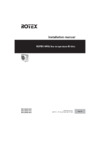
6.2 Wiring diagram
6.2.1 Wiring diagram: Outdoor unit
The wiring diagram is delivered with the unit, located at the inside of
the service cover.
Notes:
1 This wiring diagram applies only to the outdoor unit.
2 Symbols (see below).
3 Symbols (see below).
4 Refer to the option manual for connecting wiring to X6A and
X77A.
5 Refer to the wiring diagram sticker (on the back of the service
cover) for how to use the BS1~BS4 and DS1 switches.
6 When operating, do not short-circuit protective device S1PH.
7 Colours (see below).
8 Refer to the service manual for instructions on how to set the
selector switches (DS1). The factory setting of all switches is
OFF.
9 Symbols (see below).
Symbols:
L Live
N Neutral
Field wiring
Terminal strip
Connector
Connector
Connection
Protective earth (screw)
Noiseless earth
Terminal
Option
Wiring dependent on model
Colours:
BLK Black
BLU Blue
BRN Brown
GRN Green
ORG Orange
RED Red
WHT White
YLW Yellow
Legend:
A1P~A4P Printed circuit board
BS1~BS4 Push button switch
C1~C4 Capacitor
DS1 DIP switch
E1H Bottom plate heater
E1HC Crankcase heater
F1U~F8U
(RRLQ_V3)
▪ F1U, F3U, F4U: Fuse (T 6.3 A /
250V)
▪ F6U: Fuse (T 5.0A / 250V)
▪ F7U, F8U: Fuse (F 1.0A / 250V)
F1U~F9U
(RRLQ_W1)
▪ F1U, F2U: Fuse (31.5A / 500V)
▪ F3U~F6U: Fuse (T 6.3A / 250V)
▪ F7U: Fuse (T 5.0A / 250V)
▪ F8U, F9U: Fuse (F 1.0A / 250V)
H1P~H7P (A2P)
(RRLQ_V3)
Light‑emitting diode (service monitor
orange)
H2P:
▪ Prepare, test: Flickering
▪ Malfunction detection: Light up
H1P~H7P (A1P)
(RRLQ_W1)
Light‑emitting diode (service monitor
orange)
HAP (A1P)
(RRLQ_V3)
Light‑emitting diode (service monitor
green)
HAP (A1P, A2P)
(RRLQ_W1)
Light‑emitting diode (service monitor
green)
K1M, K2M
(RRLQ_W1)
Magnetic contactor (main, upload)
K1R~K4R Magnetic relay
K10R, K11R
(RRLQ_V3)
Magnetic relay
L1R~L4R Reactor
M1C Motor (compressor)
M1F Motor (upper fan)
M2F Motor (lower fan)
PS Switching power supply
Содержание
- Outdoor unit for air to water heat pump p.1
- Installation manual p.1
- Installation manual p.2
- Pw57793 2a p.3
- Low voltage 2006 95 ec p.3
- Kema nb0344 p.3
- En60335 2 40 p.3
- Electromagnetic compatibility 2004 108 ec p.3
- Dr ing franz grammling managing director 2nd of november 2010 p.3
- Tcf 21f19 06 2010 p.3
- Rrlq011caw1 rrlq014caw1 rrlq016caw1 rrlq011cav3 rrlq014cav3 rrlq016cav3 p.3
- Qua emc02 4565 p.3
- Preparing installation site p.4
- Preparation 4 p.4
- Preparation p.4
- Outdoor unit p.4
- Mounting the outdoor unit p.4
- Installation site requirements of the outdoor unit p.4
- Installation 4 p.4
- Installation p.4
- About this document p.4
- About the documentation 4 p.4
- About the documentation p.4
- To remove the accessories from the outdoor unit p.4
- About the box 4 p.4
- About the box p.4
- To provide the installation structure p.4
- Technical data 10 p.4
- Table of contents p.4
- Starting up the outdoor unit 9 p.4
- To provide drainage p.5
- To prevent the outdoor unit from falling over p.5
- To install the outdoor unit p.5
- To connect the refrigerant piping to the outdoor unit p.5
- Installation p.5
- Connecting the refrigerant piping p.5
- To determine if oil traps are required p.6
- To check for leaks p.6
- Installation p.6
- Checking the refrigerant piping p.6
- B a 4 ø6 mm p.6
- To perform vacuum drying p.7
- To fix the fluorinated greenhouse gases label p.7
- To determine the additional refrigerant amount p.7
- To charge refrigerant p.7
- Installation p.7
- Connecting the electrical wiring p.7
- Charging refrigerant p.7
- To connect the electrical wiring on the outdoor unit p.8
- Specifications of standard wiring components p.8
- Installation p.8
- About electrical compliance p.8
- To reposition the air thermistor on the outdoor unit p.9
- To finish the outdoor unit installation p.9
- Starting up the outdoor unit p.9
- Finishing the outdoor unit installation p.9
- A b c d e p.9
- Wiring diagram outdoor unit p.10
- Wiring diagram p.10
- Technical data p.10
- Service space outdoor unit p.10
- Technical data p.11
- Rotex heating systems sarl p.12
- Rotex heat i ng syst ems gmbh langwiesenstraße 10 d 74363 güglingen fon 49 7135 103 0 fax 49 7135 103 200 p.12
- P385895 1a p.12
- Errors and technical changes reserved 10 2010 p.12
- Daikin airconditioning uk ltd p.12
- Daikin airconditioning spain p.12
- Daikin airconditioning italy s p a p.12
- Daikin airconditioning belgium nv p.12
Похожие устройства
-
 Daikin RRLQ016CAW1Руководство по применению для установщика
 -
 Daikin RRLQ016CAW1Инструкция по монтажу
 -
 Daikin RRLQ016CAW1Инструкция по эксплуатации
 -
Daikin RRLQ014CAW1Руководство по применению для установщика
-
Daikin RRLQ014CAW1Инструкция по эксплуатации
-
Daikin RRLQ011CAW1Руководство по применению для установщика
-
Daikin RRLQ011CAW1Инструкция по монтажу
-
Daikin RRLQ011CAW1Инструкция по эксплуатации
-
 Daikin RRLQ008CAV3Руководство по применению для установщика
 -
 Daikin RRLQ008CAV3Инструкция по монтажу
 -
Daikin RRLQ008CAV3Инструкция по эксплуатации
-
Daikin RRLQ006CAV3Руководство по применению для установщика
Получите полное руководство по установке и техническим данным для наружного блока теплового насоса. Узнайте о минимальных расстояниях и схемах подключения.