![Daikin RRLQ014CAW1 — установка и электрические требования для тепловых насосов [8/12]](/img/pdf.png)
Daikin RRLQ014CAW1 — установка и электрические требования для тепловых насосов [8/12]
![Daikin RRLQ014CAW1 [8/12] To connect the electrical wiring on the outdoor unit](/views2/1787391/page8/bg8.png)
4 Installation
Installation manual
8
RRLQ011~016CA
Outdoor unit for air to water heat pump
4P385895-1A – 2016.03
4.5.1 About electrical compliance
RRLQ_V3
Equipment complying with:
▪ EN/IEC 61000‑3‑11
provided that the system impedance Z
sys
is
less than or equal to Z
max
at the interface point between the user's
supply and the public system.
▪ EN/IEC 61000‑3‑11 = European/International Technical
Standard setting the limits for voltage changes, voltage
fluctuations and flicker in public low-voltage supply systems for
equipment with rated current ≤75A.
▪ It is the responsibility of the installer or user of the equipment to
ensure, by consultation with the distribution network operator if
necessary, that the equipment is connected only to a supply
with a system impedance Z
sys
less than or equal to Z
max
.
▪ EN/IEC 61000‑3‑12 provided that the short-circuit power S
sc
is
greater than or equal to the minimum S
sc
value at the interface
point between the user's supply and the public system.
▪ EN/IEC 61000‑3‑12 = European/International Technical
Standard setting the limits for harmonic currents produced by
equipment connected to public low-voltage systems with input
current >16A and ≤75A per phase.
▪ It is the responsibility of the installer or user of the equipment to
ensure, by consultation with the distribution network operator if
necessary, that the equipment is connected only to a supply
with a short-circuit power S
sc
greater than or equal to the
minimum S
sc
value.
Model Z
max
Minimum S
sc
value
RRLQ011CAV3
RRLQ014CAV3
RRLQ016CAV3
0.22Ω 525kVA
RRLQ_W1
Equipment complying with EN/IEC 61000‑3‑12 (European/
International Technical Standard setting the limits for harmonic
currents produced by equipment connected to public low-voltage
systems with input current >16A and ≤75A per phase.).
4.5.2 Specifications of standard wiring
components
Component RRLQ_V3 RRLQ_W1
Power supply
cable
MCA
(a)
34.2A 16.3A
Voltage 230V 400V
Phase 1~ 3N~
Frequency 50Hz
Wire sizes Must comply with applicable
legislation
Interconnection cable Minimum cable section of
2.5mm² and applicable for
230V
Recommended field fuse 40A 20A
Earth leakage circuit breaker Must comply with applicable
legislation
(a) MCA=Minimum circuit ampacity. Stated values are
maximum values (see electrical data of combination with
indoor units for exact values).
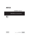
4.5.3 To connect the electrical wiring on the
outdoor unit
NOTICE
▪ Follow the wiring diagram (delivered with the unit,
located at the inside of the service cover).
▪ Make sure the electrical wiring does NOT obstruct
proper reattachment of the service cover.
1 Remove the service cover.
2 Connect the interconnection cable and power supply as follows:
c
b
a
d
V3
1~ 50 Hz
230 V
W1
3N~ 50 Hz
400 V
L1 L3L2
L1 L3L2
a Interconnection cable
b Power supply cable
c Earth leakage circuit breaker
d Fuse
d
b
a
V3 W1
e
f
d
e
f
c c
a Switch box
b Stop valve attachment plate
c Earth
d Cable tie
e Interconnection cable
f Power supply cable
3 Fix the cables (power supply, interconnection cable and power
supply of the bottom plate heater (if applicable)) with a cable tie
to the stop valve attachment plate.
4 Route the wiring through the frame and connect it to it.
Содержание
- Outdoor unit for air to water heat pump p.1
- Installation manual p.1
- Installation manual p.2
- Pw57793 2a p.3
- Low voltage 2006 95 ec p.3
- Kema nb0344 p.3
- En60335 2 40 p.3
- Electromagnetic compatibility 2004 108 ec p.3
- Dr ing franz grammling managing director 2nd of november 2010 p.3
- Tcf 21f19 06 2010 p.3
- Rrlq011caw1 rrlq014caw1 rrlq016caw1 rrlq011cav3 rrlq014cav3 rrlq016cav3 p.3
- Qua emc02 4565 p.3
- Preparing installation site p.4
- Preparation 4 p.4
- Preparation p.4
- Outdoor unit p.4
- Mounting the outdoor unit p.4
- Installation site requirements of the outdoor unit p.4
- Installation 4 p.4
- Installation p.4
- About this document p.4
- About the documentation 4 p.4
- About the documentation p.4
- To remove the accessories from the outdoor unit p.4
- About the box 4 p.4
- About the box p.4
- To provide the installation structure p.4
- Technical data 10 p.4
- Table of contents p.4
- Starting up the outdoor unit 9 p.4
- To provide drainage p.5
- To prevent the outdoor unit from falling over p.5
- To install the outdoor unit p.5
- To connect the refrigerant piping to the outdoor unit p.5
- Installation p.5
- Connecting the refrigerant piping p.5
- To determine if oil traps are required p.6
- To check for leaks p.6
- Installation p.6
- Checking the refrigerant piping p.6
- B a 4 ø6 mm p.6
- To perform vacuum drying p.7
- To fix the fluorinated greenhouse gases label p.7
- To determine the additional refrigerant amount p.7
- To charge refrigerant p.7
- Installation p.7
- Connecting the electrical wiring p.7
- Charging refrigerant p.7
- To connect the electrical wiring on the outdoor unit p.8
- Specifications of standard wiring components p.8
- Installation p.8
- About electrical compliance p.8
- To reposition the air thermistor on the outdoor unit p.9
- To finish the outdoor unit installation p.9
- Starting up the outdoor unit p.9
- Finishing the outdoor unit installation p.9
- A b c d e p.9
- Wiring diagram outdoor unit p.10
- Wiring diagram p.10
- Technical data p.10
- Service space outdoor unit p.10
- Technical data p.11
- Rotex heating systems sarl p.12
- Rotex heat i ng syst ems gmbh langwiesenstraße 10 d 74363 güglingen fon 49 7135 103 0 fax 49 7135 103 200 p.12
- P385895 1a p.12
- Errors and technical changes reserved 10 2010 p.12
- Daikin airconditioning uk ltd p.12
- Daikin airconditioning spain p.12
- Daikin airconditioning italy s p a p.12
- Daikin airconditioning belgium nv p.12
Похожие устройства
-
 Daikin RRLQ016CAW1Руководство по применению для установщика
 -
 Daikin RRLQ016CAW1Инструкция по монтажу
 -
 Daikin RRLQ016CAW1Инструкция по эксплуатации
 -
Daikin RRLQ014CAW1Руководство по применению для установщика
-
Daikin RRLQ014CAW1Инструкция по эксплуатации
-
Daikin RRLQ011CAW1Руководство по применению для установщика
-
Daikin RRLQ011CAW1Инструкция по монтажу
-
Daikin RRLQ011CAW1Инструкция по эксплуатации
-
 Daikin RRLQ008CAV3Руководство по применению для установщика
 -
 Daikin RRLQ008CAV3Инструкция по монтажу
 -
Daikin RRLQ008CAV3Инструкция по эксплуатации
-
Daikin RRLQ006CAV3Руководство по применению для установщика
Подробное руководство по установке и электрическим требованиям для наружных блоков тепловых насосов. Узнайте о стандартах и необходимых условиях подключения.