![Daikin RRLQ014CAW1 — руководство по установке наружного блока теплового насоса [6/12]](/img/pdf.png)
Daikin RRLQ014CAW1 — руководство по установке наружного блока теплового насоса [6/12]
![Daikin RRLQ014CAW1 [6/12] B a 4 ø6 mm](/views2/1787391/page6/bg6.png)
4 Installation
Installation manual
6
RRLQ011~016CA
Outdoor unit for air to water heat pump
4P385895-1A – 2016.03
c
a
b
d
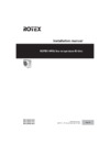
2 Choose a piping route (a, b, c or d).
a
b
c
d
3 If you have chosen the downwards piping route:
▪ Drill (a, 4×) and remove the knockout hole (b).
▪ Cut out the slits (c) with a metal saw.
cc
ba
4× Ø6 mm
4 Do the following:
▪ Connect the liquid pipe (a) to the liquid stop valve.
▪ Connect the gas pipe (b) to the gas stop valve.
a
b
5 Do the following:
▪ Insulate the liquid piping (a) and the gas piping (b).
▪ Make sure the piping and piping insulation do NOT touch the
compressor (c), the compressor terminal cover (d), and the
compressor bolts (e). If the liquid pipe insulation might touch
the compressor terminal cover, adjust the height of the
insulation (f=no insulation around the compressor terminal
cover (d)).
▪ Seal the insulation ends (sealant etc.) (g).
d
c
e
b
a
g
g
h
h
f
6 If the outdoor unit is installed above the indoor unit, cover the
stop valves (h, see above) with sealing material to prevent
condensed water on the stop valves from moving to the indoor
unit.
NOTICE
Any exposed piping might cause condensation.
7 Reattach the service cover and the piping intake plate.
8 Seal all gaps (example: a) to prevent snow and small animals
from entering the system.
a
WARNING
Provide adequate measures to prevent that the unit can be
used as a shelter by small animals. Small animals that
make contact with electrical parts can cause malfunctions,
smoke or fire.
NOTICE
Make sure to open the stop valves after installing the
refrigerant piping and performing vacuum drying. Running
the system with the stop valves closed may break the
compressor.
4.2.2 To determine if oil traps are required
If oil flows back into the outdoor unit's compressor, this might cause
liquid compression or deterioration of oil return. Oil traps in the rising
gas piping can prevent this.
If Then
The indoor unit is installed
higher than the outdoor
unit
Install an oil trap every 10m (height
difference).
a
b
10 m
a Rising gas piping with oil trap
b Liquid piping
The outdoor unit is
installed higher than the
indoor unit
Oil traps are NOT required.
4.3 Checking the refrigerant piping
4.3.1 To check for leaks
NOTICE
Do NOT exceed the unit's maximum working pressure (see
"PS High" on the unit name plate).
Содержание
- Outdoor unit for air to water heat pump p.1
- Installation manual p.1
- Installation manual p.2
- Pw57793 2a p.3
- Low voltage 2006 95 ec p.3
- Kema nb0344 p.3
- En60335 2 40 p.3
- Electromagnetic compatibility 2004 108 ec p.3
- Dr ing franz grammling managing director 2nd of november 2010 p.3
- Tcf 21f19 06 2010 p.3
- Rrlq011caw1 rrlq014caw1 rrlq016caw1 rrlq011cav3 rrlq014cav3 rrlq016cav3 p.3
- Qua emc02 4565 p.3
- Preparing installation site p.4
- Preparation 4 p.4
- Preparation p.4
- Outdoor unit p.4
- Mounting the outdoor unit p.4
- Installation site requirements of the outdoor unit p.4
- Installation 4 p.4
- Installation p.4
- About this document p.4
- About the documentation 4 p.4
- About the documentation p.4
- To remove the accessories from the outdoor unit p.4
- About the box 4 p.4
- About the box p.4
- To provide the installation structure p.4
- Technical data 10 p.4
- Table of contents p.4
- Starting up the outdoor unit 9 p.4
- To provide drainage p.5
- To prevent the outdoor unit from falling over p.5
- To install the outdoor unit p.5
- To connect the refrigerant piping to the outdoor unit p.5
- Installation p.5
- Connecting the refrigerant piping p.5
- To determine if oil traps are required p.6
- To check for leaks p.6
- Installation p.6
- Checking the refrigerant piping p.6
- B a 4 ø6 mm p.6
- To perform vacuum drying p.7
- To fix the fluorinated greenhouse gases label p.7
- To determine the additional refrigerant amount p.7
- To charge refrigerant p.7
- Installation p.7
- Connecting the electrical wiring p.7
- Charging refrigerant p.7
- To connect the electrical wiring on the outdoor unit p.8
- Specifications of standard wiring components p.8
- Installation p.8
- About electrical compliance p.8
- To reposition the air thermistor on the outdoor unit p.9
- To finish the outdoor unit installation p.9
- Starting up the outdoor unit p.9
- Finishing the outdoor unit installation p.9
- A b c d e p.9
- Wiring diagram outdoor unit p.10
- Wiring diagram p.10
- Technical data p.10
- Service space outdoor unit p.10
- Technical data p.11
- Rotex heating systems sarl p.12
- Rotex heat i ng syst ems gmbh langwiesenstraße 10 d 74363 güglingen fon 49 7135 103 0 fax 49 7135 103 200 p.12
- P385895 1a p.12
- Errors and technical changes reserved 10 2010 p.12
- Daikin airconditioning uk ltd p.12
- Daikin airconditioning spain p.12
- Daikin airconditioning italy s p a p.12
- Daikin airconditioning belgium nv p.12
Похожие устройства
-
 Daikin RRLQ016CAW1Руководство по применению для установщика
 -
 Daikin RRLQ016CAW1Инструкция по монтажу
 -
 Daikin RRLQ016CAW1Инструкция по эксплуатации
 -
Daikin RRLQ014CAW1Руководство по применению для установщика
-
Daikin RRLQ014CAW1Инструкция по эксплуатации
-
Daikin RRLQ011CAW1Руководство по применению для установщика
-
Daikin RRLQ011CAW1Инструкция по монтажу
-
Daikin RRLQ011CAW1Инструкция по эксплуатации
-
 Daikin RRLQ008CAV3Руководство по применению для установщика
 -
 Daikin RRLQ008CAV3Инструкция по монтажу
 -
Daikin RRLQ008CAV3Инструкция по эксплуатации
-
Daikin RRLQ006CAV3Руководство по применению для установщика
Подробное руководство по установке наружного блока теплового насоса. Узнайте, как правильно прокладывать трубопроводы и предотвращать конденсацию.