![ADJ Quad Phase HP — инструкция по эксплуатации для Quad Phase HP: DMX и подключение [3/10]](/img/pdf.png)
ADJ Quad Phase HP — инструкция по эксплуатации для Quad Phase HP: DMX и подключение [3/10]
Превью страниц
Страница 3 /
10
![ADJ Quad Phase HP [3/10] Special note line termination](/views2/2008551/page3/bg3.png)
ADJ Products, LLC - www.adj.com - Quad Phase HP Instruction Manual Page 6ADJ Products, LLC - www.adj.com - Quad Phase HP Instruction Manual Page 5
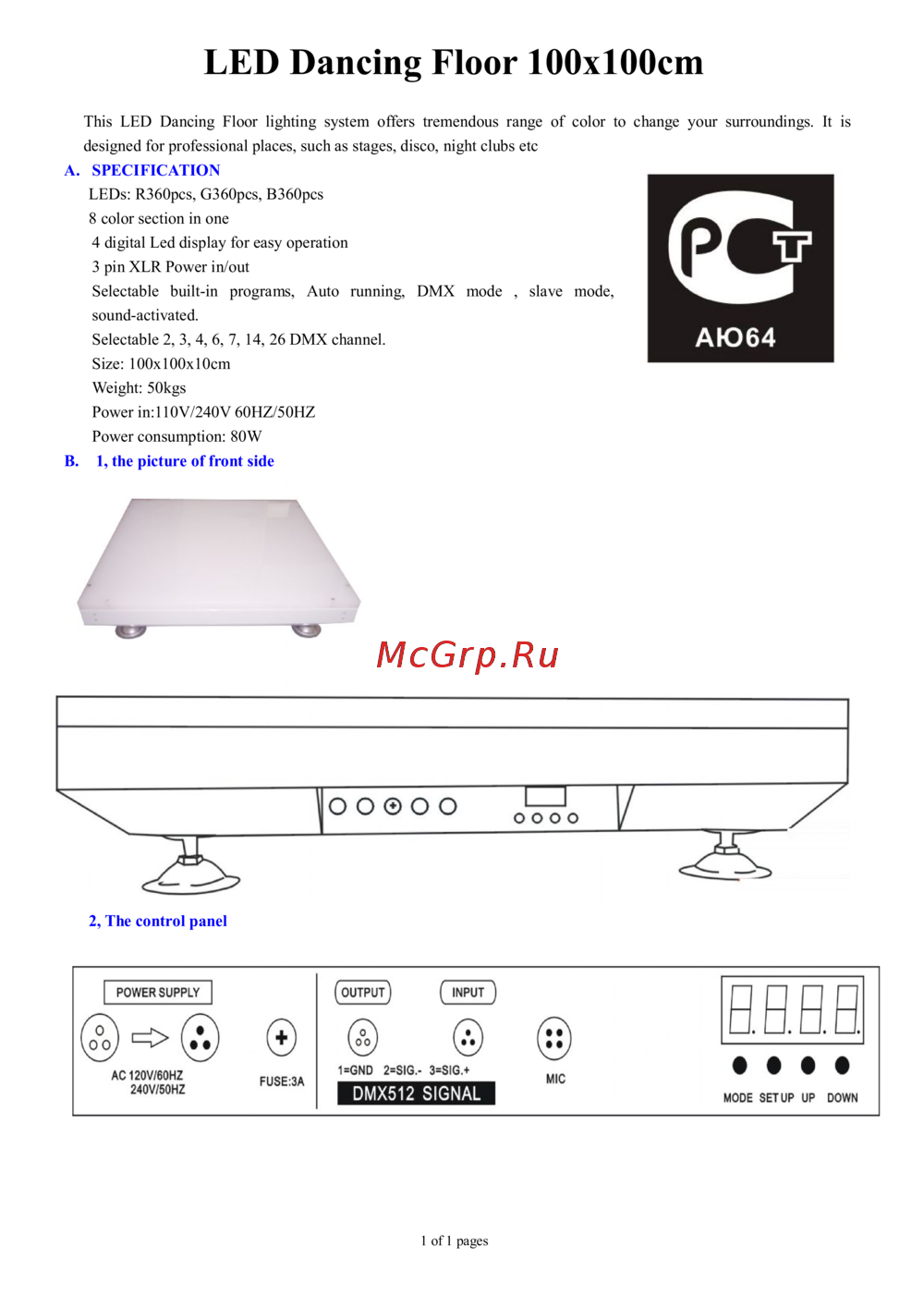
Power Supply: The ADJ Quad Phase HP contains a automatic volt-
age switch, which will auto sense the voltage when it is plugged into
the power source. With this switch there is no need to worry about the
correct power voltage, this unit can be plugged in anywhere.
DMX-512: DMX is short for Digital Multiplex. This is a universal pro-
tocol used by most lighting and controller manufactures as a form of
communication between intelligent fixtures and controllers. A DMX
controller sends DMX data instructions from the controller to the fix-
ture. DMX data is sent as serial data that travels from fixture to fixture
via the DATA “IN” and DATA “OUT” XLR terminals located on all DMX
fixtures (most controllers only have a DATA “OUT” terminal).
DMX Linking: DMX is a language allowing all makes and models of
different manufactures to be linked together and operate from a sin-
gle controller, as long as all xtures and the controller are DMX com-
pliant. To ensure proper DMX data transmission, when using several
DMX fixtures try to use the shortest cable path possible. The order
in which fixtures are connected in a DMX line does not influence the
DMX addressing. For example; a fixture assigned a DMX address of 1
may be placed anywhere in a DMX line, at the beginning, at the end,
or anywhere in the middle. When a fixture is assigned a DMX address
of 1, the DMX controller knows to send DATA assigned to address 1
to that unit, no matter where it is located in the DMX chain.
Data Cable (DMX Cable) Requirements (For DMX and Master/Slave
Operation): The Quad Phase HP can be controlled via DMX-512
protocol. The Quad Phase HP is a four channel DMX unit. The DMX
address is set electronically using the controls on the back panel of
the unit. Your unit and your DMX controller require a approved DMX-
512 110 Ohm Data cable for data input and data output (Figure 1).
We recommend Accu-Cable DMX cables. If you are
making your own cables, be sure to use standard
110-120 Ohm shielded cable (This cable may be
purchased at almost all professional sound and
lighting stores). Your cables should be made with
a male and female XLR connector on either end of
the cable. Also remember that DMX cable must be
daisy chained and cannot be split.
Quad Phase HP Set Up
Figure 1
Quad Phase HP Set Up
Notice: Be sure to follow gures two and three when making your own
cables. Do not use the ground lug on the XLR connector. Do not con-
nect the cable’s shield conductor to the ground lug or allow the shield
conductor to come in contact with the XLR’s outer casing. Grounding
the shield could cause a short circuit and erratic behavior.
DMX512 IN
3-PIN XLR
SOUND
REMOTE
CONTROL
INPUT
POWER
INPUT OUTPUT
SOUND
REMOTE
CONTROL
INPUT
POWER
INPUT OUTPUT
SOUND
REMOTE
CONTROL
INPUT
POWER
INPUT OUTPUT
DMX512
DMX+,DMX-,COMMON
1
2
3
Termination reduces signal errors and
avoids signal transmission problems
and interference. It is always advisable
to connect a DMX terminal, (Resistance
120 Ohm 1/4 W) between PIN 2 (DMX-)
and PIN 3 (DMX +) of the last fixture.
1
2
3
1
2
3
DMX +
DMX -
COMMON
DMX512 OUT
3-PIN XLR
Figure 2
Figure 3
1 Ground
1 Ground
XLR Male Socket
XLR Pin Conguration
3 Hot
2 Cold
2 Cold
3 Hot
XLR Female Socket
Pin 3 = Data True (positive)
Pin 2 = Data Compliment (negative)
Pin 1 = Ground
Special Note: Line Termination.
When longer runs of cable are
used, you may need to use a terminator on the last unit to avoid erratic
behavior. A terminator is a 110-120 ohm 1/4 watt resistor which is con-
nected between pins 2 and 3 of a male XLR connector (DATA + and
DATA -). This unit is inserted in the female XLR connector of the last
unit in your daisy chain to terminate the line. Using a cable terminator
(ADJ part number Z-DMX/T) will decrease the possibilities of erratic
behavior.
DMX512 IN
3-PIN XLR
SOUND
REMOTE
CONTROL
INPUT
POWER
INPUT OUTPUT
SOUND
REMOTE
CONTROL
INPUT
POWER
INPUT OUTPUT
SOUND
REMOTE
CONTROL
INPUT
POWER
INPUT OUTPUT
DMX512
DMX+,DMX-,COMMON
1
2
3
Termination reduces signal errors and
avoids signal transmission problems
and interference. It is always advisable
to connect a DMX terminal, (Resistance
120 Ohm 1/4 W) between PIN 2 (DMX-)
and PIN 3 (DMX +) of the last fixture.
1
2
3
1
2
3
DMX +
DMX -
COMMON
DMX512 OUT
3-PIN XLR
Figure 4
Содержание
55- Customer support
- Caution
- Warning
- User instructions
- Unpacking
- Introduction
- Caution
- Special note line termination
- Power supply
- Notice
- Dmx 512
- Pin xlr dmx connectors
- Press the menu button until temp is displayed press enter
- Press the either the menu button until ver is displayed press enter
- Press the either the menu button until fhrs is displayed press enter
- Press enter to confirm
- Pres the either the menu button until disp is displayed press enter
- With this function you can display the running time of the unit
- Master slave operation sound active
- With this function you can display the running temperature of the unit
- Use this function to display the software version of the unit
- Universal dmx control
- This function will run a self test program
- This function will reverse the display 180º
- The display will show the software version
- The display shows the running time of the unit press menu to exit
- The current running temperature of the fixture will now be displayed press menu to exit
- Sound active mode
- Press the up button to select dsip to activate this func tion or disp to deactivate this function
- On the slave units
- Channel value function
- 9 no rotation 10 120 clockwise fast slow 121 134 no rotation
- 255 color selection 1 16 color 1 17 33 color 2 34 50 color 3 51 67 color 4 68 84 color 5 85 101 color 6 102 118 color 7 119 135 color 8 136 152 color 9 153 169 color 10 170 186 color 11 187 203 color 12 204 220 color 13 221 237 color 14 238 255 color 15
- 245 counter clockwise slow fast 246 249 no rotation 250 255 sound active
- Strobing 0 off 1 255 strobing slow fast
- Shutter open 0 15 off 16 255 open
- Rotation
- Fixture cleaning
- Quad phase hp warranty
- Quad phase hp notes
- Adj products llc www adj com quad phase hp instruction manual page 17 adj products llc www adj com quad phase hp instruction manual page 18
- S eastern ave los angeles ca 90040 usa
- Please note
- Netherlands
- Model quad phase hp
- Junostraat 2
- Ew kerkrade
- Auto sensing voltage this fixture contains a automatic volt age switch which will auto sense the voltage when it is plugged into the power source
- Adj products llc
- A d j supply europe b v
- Web www adj com e mail info adj com
- Tel 323 582 2650 fax 323 725 6100
- Tel 31 45 546 85 00 fax 31 45 546 85 99
- Specifications and improvements in the design of this unit and this manual are subject to change without any prior written notice
- Service adj eu www adj com
Похожие устройства
-
 ADJ Matrix Beam LEDРуководство по эксплуатации
 -
 ADJ Tri Gem LEDРуководство по эксплуатации
 -
 Involight DD6Руководство по использованию
 -
 Involight HZ610Руководство по использованию
 -
 Involight FM900DMXИнструкция пользователя
 -
 ILDA Pangolin Quick-ShowРуководства пользователя
 -
 AMERICAN DJ Dotz TPAR SystemРуководство по эксплуатации
 -
 ADJ Hydro Beam X1Руководство по эксплуатации
 -
 Involight LDF100Руководство по эксплуатации
 -
 AMERICAN DJ Focus Spot ONEРуководство по эксплуатации
 -
 Involight LED PAR984WРуководство по эксплуатации
 -
 Antari M-7Руководство по эксплуатации
Узнайте, как правильно подключить и настроить Quad Phase HP с использованием DMX-512. Подробные инструкции по подключению и требованиям к кабелям.