![Yamaha JOG CS50 (Z) (2002) — проверка системы сигнализации: измерение напряжения и диагностика [190/204]](/img/pdf.png)
Yamaha JOG CS50 (Z) (2002) — проверка системы сигнализации: измерение напряжения и диагностика [190/204]
![Yamaha JOG CS50 (Z) (2002) [190/204] Yes no](/views2/1121429/page190/bgbe.png)
ELEC
SIGNALING SYSTEM
8-31
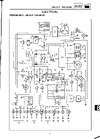
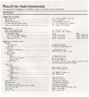
3. Voltage
• Connect the pocket tester (DC 20 V) to the
turn signal relay coupler (wire harness side)
as shown.
Positive tester probe
brown
Negative tester probe
ground
• Set the main switch to “ON”.
• Measure the voltage (DC 12 V) on brown
at the turn signal relay coupler (wire har-
ness side).
• Is the voltage within specification?
4. Voltage
• Connect the pocket tester (DC 20 V) to the
turn signal relay coupler (wire harness side)
as shown.
Positive tester probe
brown/white
Negative tester probe
ground
• Set the main switch to “ON”.
• Set the turn signal switch to “L” or “R”.
• Measure the voltage (DC 12 V) on
brown/white at the turn signal relay cou-
pler (wire harness side).
• Is the voltage within specification?
5. Voltage
• Connect the pocket tester (DC 20 V) to the
turn signal light connector or meter coupler
(wire harness side) as shown.
Turn signal light
Turn signal indicator light
Left turn signal light
Positive tester probe
chocolate
Negative tester probe
ground
Right turn signal light
Positive tester probe
dark green
Negative tester probe
ground
-
+
Br
/
W
Br
1
The wiring circuit
from the main
switch to the turn
signal relay coupler
is faulty and must
be repaired.
Br
/
W
Br
1
-
+
The turn signal
relay is faulty and
must be replaced.
LY
Br
Ch Dg
RB
Gy GR
BY Sb G LG
Dg Ch L GR Y Gy
RBrBBYSbG
RY
RYLG
Ch
B
1
2
Dg
YES
NO
YES
NO
Содержание
- Service manual p.1
- Table of contents p.1
- Notice p.3
- Important information p.3
- Detailed diagram p.4
- Format of this manual p.4
- Manual format p.4
- Important characteristics p.4
- How to use this manual p.4
- Gen info p.5
- Trbl shtg p.5
- Chk adj p.5
- Illustrated symbols p.5
- Electrical system p.6
- Carburetor p.6
- Engine p.6
- Cooling system p.6
- General information p.6
- Chassis p.6
- Troubleshooting p.6
- Table of contents p.6
- Specifications p.6
- Periodic checks and adjustments p.6
- Gen info p.8
- Chapter 1 general information p.8
- General information p.8
- Scooter identification p.9
- Gen info p.9
- Identification of scooter p.9
- General information p.9
- Important information p.10
- Gen info p.10
- Important information p.11
- Gen info p.11
- Special tools p.12
- Gen info p.12
- Special tools p.13
- Gen info p.13
- Specifications p.15
- Chapter 2 specifications p.15
- Specifications p.16
- General specifications p.16
- General specifications p.17
- Maintenance specifications p.18
- Maintenance specifications p.19
- Maintenance specifications p.20
- Maintenance specifications p.21
- All specification data in this manual are listed in si and metric units use this table to convert metric unit data to imperial unit data p.22
- Mm 8 mm 15 1 p.22
- Mm 6 mm 6 0 p.22
- Mm 14 mm 85 8 22 mm 16 mm 130 13 p.22
- Mm 12 mm 55 5 p.22
- Mm 10 mm 30 3 p.22
- Metric to imperial p.22
- General tightening torque specifications p.22
- Ex metric multiplier imperial mm x 0 3937 in 2 mm x 0 3937 0 8 in p.22
- Conversion table general tightening torques specifications p.22
- Conversion table p.22
- A b general tightening p.22
- This chart specifies tightening torques for standard fasteners with a standard iso thread pitch tightening torque specifications for special components or assemblies are provi ded for each chapter of this manual to avoid warpage tighten multi fastener assemblies in a crisscross pattern and progressive stages until the specified tightening torque is reached unless otherwise specified tighte ning torque specifications require clean dry threads components should be at room temperature p.22
- Nut bolt torques p.22
- Nm m kg p.22
- Tightening torques p.23
- Tightening torques p.24
- Cooling system l c version only p.25
- Cooling system p.25
- Cable routing p.26
- Cable routing p.27
- Cable routing p.28
- Periodic checks and ajustments p.30
- Chk adj p.30
- Chapter 3 periodic checks and adjustments p.30
- Periodic checks and adjustments p.31
- Introduction periodic maintenance lubrication intervals p.31
- Introduction p.31
- Chk adj p.31
- Periodic maintenance and lubrication intervals p.31
- Rear bodywork mudguard p.32
- Chk adj p.32
- Rear bodywork mudguard p.33
- Chk adj p.33
- Front cowling and footrest p.34
- Chk adj p.34
- Front cowling and footrest p.35
- Chk adj p.35
- Handlebar covers p.36
- Chk adj p.36
- Handlebar covers p.37
- Chk adj p.37
- Engine p.38
- Chk adj p.38
- Adjusting the engine idling speed p.38
- Chk adj p.39
- Adjusting the throttle cable free play p.39
- Chk adj p.40
- Checking the spark plug p.40
- Checking the engine oil level p.41
- Chk adj p.41
- Chk adj p.42
- Changing the transmission oil autolube pump air bleeding p.42
- Cleaning the air filter element p.43
- Chk adj p.43
- Chk adj p.44
- Checking the coolant level p.44
- Chk adj p.45
- Changing the coolant p.45
- Changing the coolant p.46
- Chk adj p.46
- Chk adj p.47
- Changing the coolant p.47
- Chassis p.48
- Chk adj p.48
- Chk adj p.49
- Checking the rear brake shoes checking the brake fluid level p.49
- Chk adj p.50
- Bleeding the hydraulic brake system p.50
- After bleeding the hydraulic brake sys tem check the brake operation p.50
- Chk adj p.51
- Checking and adjusting the steering head p.51
- Chk adj p.52
- Checking and adjusting the steering head p.52
- Chk adj p.53
- Checking the tires checking the wheels checking the front fork p.53
- Rear shock absorber inspection p.54
- Chk adj p.54
- Electrical system p.55
- Chk adj p.55
- Checking and charging the battery p.55
- Chk adj p.56
- Checking and charging the battery p.56
- Chk adj p.57
- Checking and charging the battery p.57
- Chk adj p.58
- Checking and charging the battery p.58
- Checking and charging the battery p.59
- Chk adj p.59
- Do not use fuses of a higher amperage than that recommended this can cause extensive damage to the electri cal system and fire p.60
- Chk adj p.60
- Checking and charging the battery checking the fuse p.60
- Replacing the headlight bulb adjusting the headlight beam p.61
- Chk adj p.61
- Engine p.63
- Chapter 4 engine p.63
- Engine removal p.64
- Engine p.64
- Engine removal p.65
- Engine disassembly p.66
- Engine disassembly p.67
- Engine disassembly p.68
- Engine disassembly p.69
- Engine disassembly p.70
- Engine disassembly p.71
- Engine disassembly p.72
- Engine disassembly p.73
- Inspection and repair p.74
- Inspection and repair p.75
- Inspection and repair p.76
- Inspection and repair p.77
- Inspection and repair p.78
- Inspection and repair p.79
- Inspection and repair p.80
- Inspection and repair p.81
- Inspection and repair p.82
- Inspection and repair p.83
- Inspection and repair p.84
- Engine assembly and adjustment p.85
- Engine assembly and adjustment p.86
- Engine assembly and adjustment p.87
- Engine assembly and adjustment p.88
- Engine assembly and adjustment p.89
- Engine assembly and adjustment p.90
- Engine assembly and adjustment p.91
- Engine assembly and adjustment p.92
- Engine assembly and adjustment p.93
- Engine assembly and adjustment p.94
- Engine assembly and adjustment p.95
- Engine assembly and adjustment p.96
- Engine assembly and adjustment p.97
- Engine assembly and adjustment p.98
- Engine assembly and adjustment p.99
- Engine assembly and adjustment p.100
- Engine assembly and adjustment p.101
- Engine assembly and adjustment p.102
- Engine assembly and adjustment p.103
- Engine assembly and adjustment p.104
- Engine assembly and adjustment p.105
- Chapter 5 cooling system cs50z only p.108
- Cooling system cs50z only p.108
- Radiator and water pump p.109
- Cooling system cs50z only p.109
- Radiator and water pump p.110
- Radiator and water pump p.111
- Radiator and water pump p.112
- Radiator and water pump thermostat p.113
- Thermostat p.113
- Thermostat p.114
- Carburetor p.117
- Chapter 6 carburetor p.117
- Carburetor p.118
- Carburetor p.119
- Carburetor p.120
- Carburetor p.121
- Carburetor p.122
- Carburetor p.123
- Fuel cock p.124
- Carburetor fuel cock p.124
- Reed valve p.125
- Reed valve p.126
- Chassis p.128
- Chapter 7 chassis p.128
- Front wheel p.129
- Chassis p.129
- Front wheel p.130
- Front wheel p.131
- Front wheel p.132
- Front wheel p.133
- Front wheel p.134
- Front brake p.135
- Front brake p.136
- Front brake p.137
- Front brake p.138
- Front brake p.139
- Front brake p.140
- Rear wheel p.141
- Rear wheel p.142
- Rear brake cable brake shoes plain washer p.142
- Rear wheel p.143
- Rear wheel p.144
- Front fork p.145
- Front fork p.146
- Front fork p.147
- Front fork p.148
- Front fork p.149
- Front fork p.150
- Handlebar and steering p.151
- Handlebar and steering p.152
- Handlebar and steering p.153
- Handlebar and steering p.154
- Handlebar and steering p.155
- Handlebar and steering p.156
- Chapter 8 electrical system p.159
- Electrical system p.159
- Electrical system p.160
- Electrical components p.160
- Electrical components p.161
- Checking switch continuty p.162
- Checking switch continuity p.162
- Checking the switches p.163
- Checking the bulbs and bulb sockets p.164
- Checking the bulbs and bulb sockets p.165
- Checking the bulbs and bulb sockets p.166
- Ignition system p.167
- Yes no p.168
- Ignition system p.168
- Yes no p.169
- Ignition system p.169
- Yes no p.170
- Ignition system p.170
- Electric starting system p.171
- Electric starting system p.172
- Yes no p.173
- Electric starting system p.173
- Yes no p.174
- Electric starting system p.174
- Electric starting system p.175
- Electric starting system p.176
- Electric starting system p.177
- Charging system p.178
- Yes no p.179
- No yes p.179
- Charging system p.179
- Charging system p.180
- Yes no p.180
- Lighting system p.181
- Yes no p.182
- Lighting system p.182
- Yes no p.183
- Lighting system p.183
- Yes no yes no p.184
- Yes no p.184
- Lighting system p.184
- Yes no p.185
- Lighting system p.185
- Signaling system p.186
- Yes no p.187
- Signaling system p.187
- Yes no p.188
- Signaling system p.188
- Yes no p.189
- Signaling system p.189
- Yes no p.190
- Signaling system p.190
- Yes no p.191
- Signaling system p.191
- Yes no p.192
- Signaling system p.192
- Yes no p.193
- Signaling system p.193
- Signaling system p.194
- Yes no p.194
- Troubleshooting p.196
- Trbl shtg p.196
- Chapter 9 troubleshooting p.196
- Starting failure hard starting p.197
- Troubleshooting p.197
- Trbl shtg p.197
- Trbl shtg p.198
- Starting failure hard starting incorrect engine idling speed p.198
- Incorrect engine idling speed p.198
- Trbl shtg p.199
- Poor medium and high speed performance faulty clutch p.199
- Poor medium and high speed performance p.199
- Faulty clutch p.199
- Overheating p.200
- Overcooling cs50z only p.200
- Trbl shtg p.200
- Poor braking performance p.200
- Overheating overcooling poor braking performance p.200
- Unstable handling p.201
- Trbl shtg p.201
- Faulty front fork legs unstable handling p.201
- Faulty front fork legs p.201
- Trbl shtg p.202
- Faulty lighting or signaling system p.202
- Wiring diagram p.204
- Cs50 z 2002 wiring diagram p.204
- Color code p.204
Похожие устройства
-
 Yamaha Yamaha WR250F (2003)Руководства пользователя
 -
 Yamaha FZR400Инструкция 6
 -
 Yamaha FZR400Инструкция 5
 -
 Yamaha FZR400Инструкция 4
 -
 Yamaha FZR400Инструкция 3
 -
 Yamaha FZR400Инструкция 2
 -
 Yamaha FZR400Инструкция 1
 -
 Yamaha FZS600 (2002)Инструкция 2
 -
 Yamaha FZS600 (2002)Инструкция 1
 -
 Yamaha RD350 YPVS (1984-1986)Инструкция 11
 -
 Yamaha RD350 YPVS (1984-1986)Инструкция 10
 -
 Yamaha RD350 YPVS (1984-1986)Инструкция 9
Узнайте, как правильно измерить напряжение в системе сигнализации. Пошаговая инструкция по подключению тестера и диагностике неисправностей.