
Scythe Zipang 2 Инструкция по эксплуатации онлайн
Содержание
Похожие устройства
- DF hBattery-01 Black для HTC One Dual Sim 4200 mAh Инструкция по эксплуатации
- Sony VAIO VPCF24C5E Инструкция по эксплуатации
- Scythe Orochi Rev. B Инструкция по эксплуатации
- Sony VAIO VPCF24A4E Инструкция по эксплуатации
- Russell Hobbs 20370-56 Инструкция по эксплуатации
- Scythe Ninja 3 Инструкция по эксплуатации
- Sony VAIO VPCF23Z1R Инструкция по эксплуатации
- Russell Hobbs Cottage Cream 18259-56 Инструкция по эксплуатации
- Scythe Mugen 2 Инструкция по эксплуатации
- Sony VAIO VPCF22M0E Инструкция по эксплуатации
- Scythe Zipang Инструкция по эксплуатации
- Russell Hobbs Cottage Red 18260-57 Инструкция по эксплуатации
- Sony VAIO VPCF22L1E Инструкция по эксплуатации
- Sony VAIO VPCF22J1E Инструкция по эксплуатации
- Scythe Ninja Mini Rev. B Инструкция по эксплуатации
- Russell Hobbs 19650-56 Инструкция по эксплуатации
- Scythe Kama Cross Инструкция по эксплуатации
- Sony VAIO VPCF22E1R Инструкция по эксплуатации
- Scythe BIG Shuriken Инструкция по эксплуатации
- Fornelli PGA 60 QUADRO BL Инструкция по эксплуатации
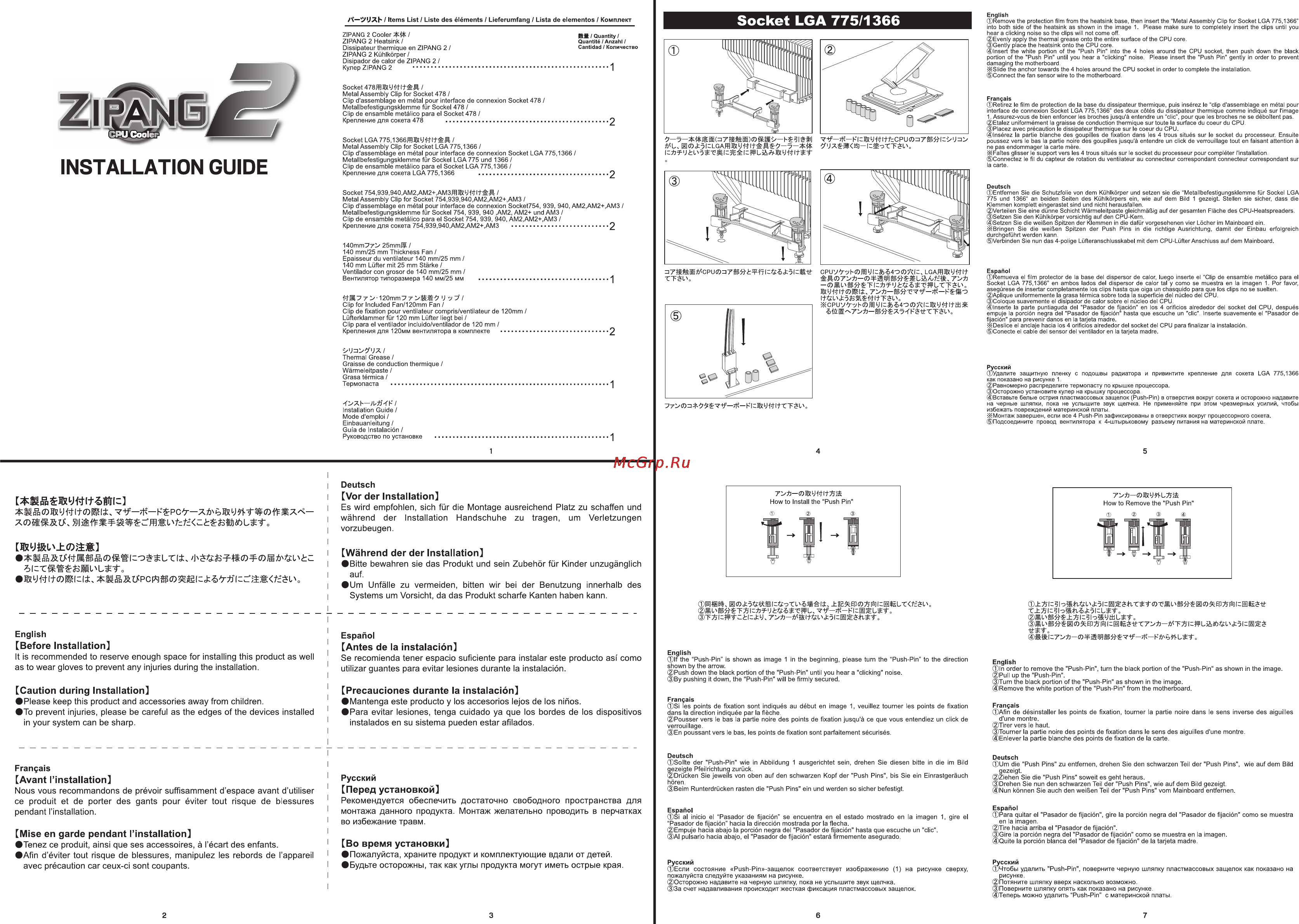
English Remove the protection film from the heatsink base then insert the Metal Assembly Clip for Socket LGA 775 1366 into both side of the heatsink as shown in the image 1 Please make sure to completely insert the clips until you hear a clicking noise so the clips will not come off Evenly apply the thermal grease onto the entire surface of the CPU core Gently place the heatsink onto the CPU core Insert the white portion of the Push Pin into the 4 holes around the CPU socket then push down the black portion of the Push Pin until you hear a clicking noise Please insert the Push Pin gently in order to prevent damaging the motherboard SI ide the anchor towards the 4 holes around the CPU socket in order to complete the installation Connect the fan sensor wire to the motherboard Socket LGA 775 1366 A J JXb Items List Liste des éléments Lieferumfang Lista de elementos Комплект ZIPANG 2 Cooler ZIPANG 2 Heatsink Dissipateur thermique en ZIPANG 2 ZIPANG 2 Kühlkörper Disipador de calor de ZIPANG 2 Кулер ZIPANG 2 Sil Quantity Quantité Anzahl Cantidad Количество Socket Metal Assembly Clip for Socket 478 Clip d assemblage en métal pour interface de connexion Socket 478 Metallbefestigungsklemme für Sockel 478 Clip de ensamble metálico para el Socket 478 Крепление для сокета 478 Français Retirez le film de protection de la base du dissipateur thermique puis insérez le clip d assemblage en métal pour interface de connexion Socket LGA 775 1366 des deux côtés du dissipateur thermique comme indiqué sur l image 1 Assurez vous de bien enfoncer les broches jusqu à entendre un clic pour que les broches ne se déboîtent pas Etalez uniformément la graisse de conduction thermique sur toute la surface du coeur du CPU Placez avec précaution le dissipateur thermique sur le coeur du CPU Insérez la partie blanche des goupilles de fixation dans les 4 trous situés sur le Socket du processeur Ensuite poussez vers le bas la partie noire des goupilles jusqu à entendre un click de verrouillage tout en faisant attention à ne pas endommager la carte mère 21 Faîtes glisser le support vers les 4 trous situés sur le Socket du processeur pour compléter l installation Connectez le fil du capteur de rotation du ventilateur au connecteur correspondant connecteur correspondant sur la carte 2 INSTALLATION GUIDE Socket LGA775 1366ffl yU M Metal Assembly Clip for Socket LGA 775 1366 Clip d assemblage en métal pour interface de connexion Socket LGA 775 1366 Metallbefestigungsklemme für Sockel LGA 775 und 1366 Clip de ensamble metálico para el Socket LGA 775 1366 Крепление для сокета LGA 775 1366 7 F 3lë i v 7k FiL y itfcCPUO iT L ij i 2 Deutsch Entfernen Sie die Schutzfolie von dem Kühlkörper und setzen sie die Metallbefestigungsklemme für Sockel LGA 775 und 1366 an beiden Seiten des Kühlkörpers ein wie auf dem Bild 1 gezeigt Stellen sie sicher dass die Klemmen komplett eingerastet sind und nicht herausfallen Verteilen Sie eine dünne Schicht Wärmeleitpaste gleichmäßig auf der gesamten Fläche des CPU Heatspreaders Setzen Sie den Kühlkörper vorsichtig auf den CPU Kern Setzen Sie die weißen Spitzen der Klemmen in die dafür vorgesehenen vier Löcher im Mainboard ein 21Bringen Sie die weißen Spitzen der Push Pins in die richtige Ausrichtung damit der Einbau erfolgreich durchgeführt werden kann Verbinden Sie nun das 4 polige Lüfteranschlusskabel mit dem CPU Lüfter Anschluss auf dem Mainboard Socket 754 939 940 AM2 AM2 AM3fflff J Metal Assembly Clip for Socket 754 939 940 AM2 AM2 AM3 Clip d assemblage en métal pour interface de connexion Socket754 939 940 AM2 AM2 AM3 Metallbefestigungsklemme für Sockel 754 939 940 AM2 AM2 und AM3 Clip de ensamble metálico para el Socket 754 939 940 AM2 AM2 AM3 Крепление для сокета 754 939 940 AM2 AM2 AM3 2 140mm7T 25mmJÏ 140 mm 25 mm Thickness Fan Epaisseur du ventilateur 140 mm 25 mm 140 mm Lüfter mit 25 mm Stärke Ventilador con grosor de 140 mm 25 mm Вентилятор типоразмера 140 мм 25 мм J I Clip for Included Fan 120mm Fan Clip de fixation pour ventilateur compris ventilateur de 120mm Lüfterklammer für 120 mm Lüfter liegt bei Clip para el ventilador incluido ventilador de 120 mm Крепления для 120мм вентилятора в комплекте CPUV ybOJ U Z 5 40 D A Z4 LGAfflæUW TTél o жсри F W у ÍL 4О СО Л гж У М It tti sit 2 iJzi yiJX Thermal Grease I Graisse de conduction thermique Wärmeleitpaste Grasa térmica Термопаста Español Remueva el film protector de la base del dispersor de calor luego inserte el Clip de ensamble metálico para el Socket LGA 775 1366 en ambos lados del dispersor de calor tal y como se muestra en la imagen 1 Por favor asegúrese de insertar completamente los clips hasta que oiga un chasquido para que los clips no se suelten Aplique uniformemente la grasa térmica sobre toda la superficie del núcleo del CPU Coloque suavemente el disipador de calor sobre el núcleo del CPU Inserte la parte puntiaguda del Pasador de fijación en los 4 orificios alrededor del Socket del CPU después empuje la porción negra del Pasador de fijación hasta que escuche un clic Inserte suavemente el Pasador de fijación para prevenir daños en la tarjeta madre 2 Deslice el anclaje hacia los 4 orificios alrededor del Socket del CPU para finalizar la instalación Conecte el cable del sensor del ventilador en la tarjeta madre Русский Удалите защитную пленку с подошвы радиатора и привинтите крепление для сокета LGA 775 1366 как показано на рисунке 1 Равномерно распределите термопасту по крышке процессора Осторожно установите кулер на крышку процессора Вставьте белые острия пластмассовых защелок Push Pin в отверстия вокруг сокета и осторожно надавите на черные шляпки пока не услышите звук щелчка Не применяйте при этом чрезмерных усилий чтобы избежать повреждений материнской платы 21 Монтаж завершен если все 4 Push Pin зафиксированы в отверстиях вокруг процессорного сокета Подсоедините провод вентилятора к 4 штырьковому разъему питания на материнской плате Installation Guide Mode d emploi Einbauanleitung Guía de Instalación Руководство по установке Deutsch ä Wi aWz ЖУШ 0 Ж Vor der Installation Es wird empfohlen sich für die Montage ausreichend Platz zu schaffen und während der Installation Handschuhe zu tragen um Verletzungen vorzubeugen Während der der Installation Bitte bewahren sie das Produkt und sein Zubehör für Kinder unzugänglich auf Um Unfälle zu vermeiden bitten wir bei der Benutzung innerhalb des Systems um Vorsicht da das Produkt scharfe Kanten haben kann English Español Before Installation Antes de la instalación It is recommended to reserve enough space for installing this product as well as to wear gloves to prevent any injuries during the installation Se recomienda tener espacio suficiente para instalar este producto así como utilizar guantes para evitar lesiones durante la instalación Caution during Installation Precauciones durante la instalación Please keep this product and accessories away from children To prevent injuries please be careful as the edges of the devices installed in your system can be sharp Mantenga este producto y los accesorios lejos de los niños Para evitar lesiones tenga cuidado ya que los bordes de los dispositivos instalados en su sistema pueden estar afilados Français Avant l installation Nous vous recommandons de prévoir suffisamment d espace avant d utiliser ce produit et de porter des gants pour éviter tout risque de blessures pendant l installation Русский Перед установкой Рекомендуется обеспечить достаточно свободного пространства для монтажа данного продукта Монтаж желательно проводить в перчатках во избежание травм Mise en garde pendant l installation Tenez ce produit ainsi que ses accessoires à l écart des enfants Afin d éviter tout risque de blessures manipulez les rebords de l appareil avec précaution car ceux ci sont coupants Во время установки Пожалуйста храните продукт и комплектующие вдали от детей Будьте осторожны так как углы продукта могут иметь острые края English lf the Push Pin is shown as image 1 in the beginning please turn the Push Pin to the direction shown by the arrow Push down the black portion of the Push Pin until you hear a clicking noise By pushing it down the Push Pin will be firmly secured Français Si les points de fixation sont indiqués au début en image 1 veuillez tourner les points de fixation dans la direction indiquée par la flèche Pousser vers le bas la partie noire des points de fixation jusqu à ce que vous entendiez un click de verrouillage En poussant vers le bas les points de fixation sont parfaitement sécurisés English ln order to remove the Push Pin turn the black portion of the Push Pin as shown in the image Pull up the Push Pin Turn the black portion of the Push Pin as shown in the image Remove the white portion of the Push Pin from the motherboard Français Afin de désinstaller les points de fixation tourner la partie noire dans le sens inverse des aiguilles d une montre Tirer vers le haut Tourner la partie noire des points de fixation dans le sens des aiguilles d une montre Enlever la partie blanche des points de fixation de la carte Deutsch Sollte der Push Pin wie in Abbildung 1 ausgerichtet sein drehen Sie diesen bitte in die im Bild gezeigte Pfeilrichtung zurück Drücken Sie jeweils von oben auf den schwarzen Kopf der Push Pins bis Sie ein Einrastgeräuch hören Beim Runterdrücken rasten die Push Pins ein und werden so sicher befestigt Deutsch Um die Push Pins zu entfernen drehen Sie den schwarzen Teil der Push Pins wie auf dem Bild gezeigt Ziehen Sie die Push Pins soweit es geht heraus Drehen Sie nun den schwarzen Teil der Push Pins wie auf dem Bild gezeigt Nun können Sie auch den weißen Teil der Push Pins vom Mainboard entfernen Español S al inicio el Pasador de fijación se encuentra en el estado mostrado en la imagen 1 gire el Pasador de fijación hacia la dirección mostrada por la flecha Empuje hacia abajo la porción negra del Pasador de fijación hasta que escuche un clic AI pulsarlo hacia abajo el Pasador de fijación estará firmemente asegurado Español Para quitar el Pasador de fijación gire la porción negra del Pasador de fijación como se muestra en la imagen Tire hacia arriba el Pasador de fijación Gire la porción negra del Pasador de fijación como se muestra en la imagen Quite la porción blanca del Pasador de fijación de la tarjeta madre Русский Если состояние РизЬ Рт защелок соответствует изображению 1 на пожалуйста следуйте указаниям на рисунке Осторожно надавите на черную шляпку пока не услышите звук щелчка 3а счет надавливания происходит жесткая фиксация пластмассовых защелок Русский Чтобы удалить Push Pin поверните черную шляпку пластмассовых защелок как показано на рисунке Потяните шляпку вверх насколько возможно Поверните шляпку опять как показано на рисунке Теперь можно удалить Push Pin с материнской платы рисунке сверху