
Pioneer DEQ-P6600 Руководство по установке онлайн
INSTALLATION MANUAL
MANUEL D’INSTALLATION
1
2
3
6
5
4
11
12
Fig. 1
Abb. 1
Afb. 1
Fig. 3
Abb. 3
Afb. 3
Fig. 2
Abb. 2
Afb. 2
7
8
<KSNNF> <04D00000>
DEQ-P6600
Printed in Japan
Imprimé au Japon
<CRD3876-A> EW
This product conforms to new cord colors.
Los colores de los cables de este producto se confor-
man con un nuevo código de colores.
Dieses Produkt entspricht den neuen Kabelfarben.
Le code de couleur des câbles utilisé pour ce produit
est nouveau.
Questo prodotto è conforme ai nuovi codici colori.
De kleuren van de snoeren van dit toestel zijn gewijzigd.
9
10
Fig. 4
Abb. 4
Afb. 4
Note:
• This unit is for vehicles with a 12-volt battery
and negative grounding. Before installing it in a
recreational vehicle, truck, or bus, check the bat-
tery voltage.
• To avoid shorts in the electrical system, be sure
to disconnect the · battery cable before begin-
ning installation.
• Refer to the owner’s manual for details on con-
necting the power amp and other units, then
make connections correctly.
• Secure the wiring with cable clamps or adhesive
tape. To protect the wiring, wrap adhesive tape
around them where they lie against metal parts.
• Route and secure all wiring so it cannot touch
any moving parts, such as the gear shift, hand-
brake and seat rails. Do not route wiring in
places that get hot, such as near the heater outlet.
If the insulation of the wiring melts or gets torn,
there is a danger of the wiring short-circuiting to
the vehicle body.
• Don’t pass the yellow lead through a hole into
the engine compartment to connect to the battery.
This will damage the lead insulation and cause a
very dangerous short.
• Do not shorten any leads. If you do, the protec-
tion circuit may fail to work when it should.
• Never feed power to other equipment by cutting
the insulation of the power supply lead of the
unit and tapping into the lead. The current capac-
ity of the lead will be exceeded, causing over-
heating.
• When replacing fuse, be sure to use only fuse of
the rating prescribed on the fuse holder.
• Since a unique BPTL circuit is employed, never
wire so the speaker leads are directly grounded or
the left and right · speaker leads are common.
• Speakers connected to this unit must be high-
power types with minimum rating of 50 W and
impedance of 4 to 8 ohms. Connecting speakers
with output and/or impedance values other than
those noted here may result in the speakers catch-
ing fire, emitting smoke or becoming damaged.
• When this product’s source is switched ON, a
control signal is output through the blue/white
lead. Connect to an external power amp’s system
remote control or the car’s Auto-antenna relay
control terminal (max. 300 mA 12 V DC). If the
car features a glass antenna, connect to the anten-
na booster power supply terminal.
• When an external power amp is being used with
this system, be sure not to connect the blue/white
lead to the amp’s power terminal. Likewise, do
not connect the blue/white lead to the power ter-
minal of the auto-antenna. Such connection could
cause excessive current drain and malfunction.
• To avoid short-circuiting, cover the disconnected
lead with insulating tape. Especially, insulate the
unused speaker leads without fail. There is a pos-
sibility of short-circuiting if the leads are not
insulated.
• To prevent incorrect connection, the input side of
the IP-BUS or optical cable connector is blue,
and the output side is black. Connect the connec-
tors of the same colors correctly.
• If this unit is installed in a vehicle that does not
have an ACC (accessory) position on the ignition
switch, the red lead of the unit should be con-
nected to a terminal coupled with ignition switch
ON/OFF operations. If this is not done, the vehi-
cle battery may be drained when you are away
from the vehicle for several hours.
• The black lead is ground. Please ground this lead
separately from the ground of high-current prod-
ucts such as power amps.
If you ground the products together and the
ground becomes detached, there is a risk of dam-
age to the products or fire.
• To ensure proper heat dissipation of this product,
take special care not to block the cooling fan side
of this product.
No ACC positionACC position
O
N
S
T
A
R
T
O
F
F
A
C
C
O
N
S
T
A
R
T
O
F
F
Note:
• Before finally installing the unit, connect the
wiring temporarily, making sure it is all connect-
ed up properly, and the unit and the system work
properly.
• Use only the parts included with the unit to
ensure proper installation. The use of unautho-
rized parts can cause malfunctions.
• Consult with your nearest dealer if installation
requires the drilling of holes or other modifica-
tions of the vehicle.
• Install the unit where it does not get in the dri-
ver’s way and cannot injure the passenger if there
is a sudden stop, like an emergency stop.
• When mounting this unit, make sure none of the
leads are trapped between this unit and the sur-
rounding metalwork or fittings.
• Do not mount this unit near the heater outlet,
where it would be affected by heat, or near the
doors, where rainwater might splash onto it.
• Before drilling any mounting holes always check
behind where you want to drill the holes. Do not
drill into the gas line, brake line, electrical wiring
or other important parts.
• If this unit is installed in the passenger compart-
ment, anchor it securely so it does not break free
while the car is moving, and cause injury or an
accident.
• If this unit is installed under a front seat, make
sure it does not obstruct seat movement. Route
all leads and cords carefully around the sliding
mechanism so they do not get caught or pinched
in the mechanism and cause a short circuit.
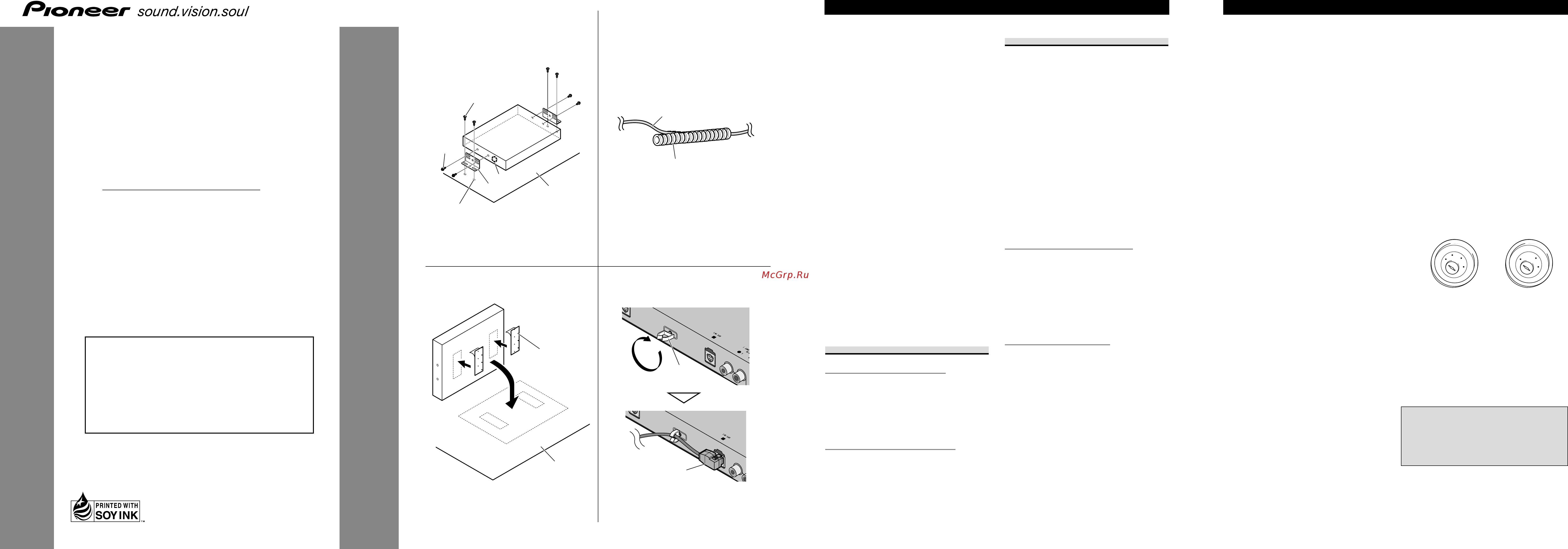
Installing the unit
Mounting with brackets (Fig. 1)
1. Tapping screw (4 × 12 mm)
2. Screw (4 × 8 mm)
3. Bracket
4. Do not close this area.
5. Drill 2 to 2.5 mm diameter holes.
6. Car mat or chassis
Mounting with velcro tape (Fig. 2)
Thoroughly wipe off the surface before affixing
the velcro tape.
7. Velcro tape
8. Car mat or chassis
Routing the optical cable
Precaution:
• Try not to bend the optical cable sharply. If it is
necessary to bend it sharply, make sure that the
bending radius is at least 25 mm, otherwise the
cable will not transfer signals properly and so
this unit will not work properly.
• Route the optical cable so that nothing heavy
rests on it, and so that it cannot be stepped on or
caught in anything – for instance, a door.
• Make a loop of diameter at least 200 mm with
the remaining optical cable so that the cable does
not get strained.
• When plugging the optical cable into the unit,
use the supplied cable clamps to prevent the
cable from being bent sharply.
• Route the optical cable so that it does not get
caught in moving parts such as the gear shift,
hand brake, or seat sliding mechanism. Keep the
cable away from hot spots, such as near the
heater outlet.
Using the corrugated tube (Fig. 3)
To prevent the optical cable from being strained,
use the corrugated tube after cutting it to the cor-
rect length.
• Insert the optical cable into the cor-
rugated tube.
9. Optical cable
10. Corrugated tube
Mounting the clamp (Fig. 4)
The clamp is used to secure the optical cable
when using it. The other clamp is installed on the
back side of the head unit similarly and used to
secure the optical cable.
1. Insert the clamp in the direction
indicated in the figure, and turn it 90
degrees to lock.
11. Clamp
2. Secure the optical cable.
12. Optical cable
Installation <ENGLISH> Connecting the Units <ENGLISH>
• Cords for this product and those for other prod-
ucts may be different colors even if they have
the same function. When connecting this prod-
uct to another product, refer to the supplied
manuals of both products and connect cords that
have the same function.
Содержание
- Deq p6600 1
- Installation manual 1
- Installing the unit 1
- Manuel d installation 1
- Routing the optical cable 1
- Anbringen der klemme abb 4 2
- Asegure el cable óptico 2
- Das lichtleiterkabel sichern 2
- Die klemme in der in der abbildung gezeigten ausrichtung einsetzen und zur verriegelung um 90 grad drehen 2
- Einbau des geräts 2
- Encaminamiento del cable óptico 2
- Führen sie das lichtleiterkabel in das wellrohr ein 2
- Gebrauch des wellrohrs abb 3 2
- Hinweis 2
- Inserte el cable óptico en el tubo ondulado 2
- Inserte la abrazadera en la dirección indicada en la figura y gírela en 90 grados para asegurarla 2
- Instalación de la unidad 2
- Montage mit halterungen abb 1 2
- Montage mit klettband abb 2 2
- Montaje con cinta adherente fig 2 2
- Montaje con ménsulas fig 1 2
- Montaje de la abrazadera fig 4 2
- Precaución 2
- Uso del tubo ondulado fig 3 2
- Verlegen des lichtleiterkabels 2
- Zur besonderen beachtung 2
- Cheminement du câble optique 3
- Fissare il cavo ottico 3
- Fixation avec la bande velcro fig 2 3
- Fixation avec les équerres fig 1 3
- Fixation du collier fig 4 3
- Fixez le câble optique 3
- Inserire il cavo ottico nel tubo spi ralato 3
- Inserire il morsetto nella direzione indicata in figura e ruotarlo poi di 90 gradi per bloccarlo 3
- Installation de l appareil 3
- Installazione dell apparecchio 3
- Introduisez le collier dans les sens indiqué sur la figure puis tournez le de 90 degrés pour assurer son maintien 3
- Introduisez le câble optique dans le tube annelé 3
- Montaggio del morsetto fig 4 3
- Per mezzo del nastro autoadesivo fig 2 3
- Per mezzo delle staffe fig 1 3
- Posa del cavo ottico 3
- Uso del tubo spiralato fig 3 3
- Utilisation du tube annelé fig 3 3
- Bevestigen met beugels afb 1 4
- Bevestigen met velcroband afb 2 4
- Bevestigen van de klem afb 4 4
- Fig 5 abb 5 afb 5 4
- Fig 6 abb 6 afb 6 4
- Gebruik van de geribbelde buis afb 3 4
- Installeren van het toestel 4
- Leggen van de optische kabel 4
- Opmerking 4
- Steek de klem in de richting die in de afbeelding is aangegeven draai 90 graden om te vergrendelen 4
- Steek de optische kabel in de geribbelde buis 4
- Voorzorgen 4
- Zet de los optische kabel vast 4
- Fig 10 abb 10 afb 10 5
- Fig 11 abb 11 afb 11 5
- Fig 7 abb 7 afb 7 5
- Fig 8 abb 8 afb 8 5
- Fig 9 abb 9 afb 9 5
- Conectando a un amplificador de potencia vendido separadamente fig 6 6
- Conexión al sistema fig 7 6
- Conexión con receptor av reproductor de dvd fig 7 6
- Conexión con unidad principal de dvd fig 8 6
- Conexión del cable de alimentación fig 5 6
- Conexión del cable óptico fig 9 6
- Conexión e instalación de la caja de conexión de cable óptico 6
- Connecting and installing the optical cable connection box 6
- Connecting the optical cable fig 9 6
- Connecting the power cord fig 5 6
- Connecting the system 6
- Connecting to a sold separately power amp fig 6 6
- Connecting with av receiver dvd player fig 7 6
- Connecting with dvd head unit fig 8 6
- Anschluss an einen getrennt erhältlichen leistungsverstärker abb 6 7
- Anschluss des betriebsstromkabels 7
- Anschluss des systems 7
- Anschluss und installation der lichtleiterkabel anschlussbox 7
- Branchement du cordon d alimentation fig 5 7
- Raccordement au récepteur audiovisuel lecteur de dvd fig 7 7
- Raccordement du câble à fibres optiques fig 9 7
- Raccordement du système 7
- Raccordement et installation de la boîte de raccordment de câble à fibres optiques 7
- Raccordement à l appareil central et lecteur de dvd fig 8 7
- Raccordement à un amplificateur vendu séparément fig 6 7
- Verbindung mit av receiver dvd player abb 7 7
- Verbindung mit dvd hauptgerät abb 8 7
- Aansluiten en installeren van de optische kabel aansluitkast 8
- Aansluiten op een av receiver dvd speler afb 7 8
- Aansluiten op een dvd hoofdtoestel afb 8 8
- Aansluiten op een een los verkrijgbare eindversterker afb 6 8
- Aansluiten van de optische kabel afb 9 8
- Aansluiten van het stroomsnoer afb 5 8
- Aansluiten van het systeeem 8
- Collegament ed installazione della scatola di conessione del cavo ottico 8
- Collegamento ad un amplificatore di potenza venduto a parte fig 6 8
- Collegamento al ricevitore av lettore dvd fig 7 8
- Collegamento all unità principale dvd fig 8 8
- Collegamento del cavo di alimentazione fig 5 8
- Collegamento del cavo ottico fig 9 8
- Collegamento del sistema 8
Похожие устройства
- Pioneer DEQ-P6600 Руководство пользователя
- Pioneer DEQ-P7000 Руководство по установке
- Pioneer DEQ-P7000 Руководство пользователя
- Pioneer DEQ-P9 Руководство пользователя
- Pioneer DEQ-P90 Руководство пользователя
- Pioneer GM-D8400M Руководство по установке
- Pioneer GM-D8400M Руководство пользователя
- Pioneer PRS-A900 Руководство пользователя
- Pioneer RS-P90 Руководство пользователя
- Pioneer AVH-2400BT Краткое руководство
- Pioneer AVH-2400BT Руководство по установке
- Pioneer AVH-2400BT Руководство пользователя
- Pioneer AVH-3400DVD Краткое руководство
- Pioneer AVH-3400DVD Руководство пользователя
- Pioneer AVH-3400DVD Руководство по установке
- Pioneer AVH-4400BT Руководство пользователя
- Pioneer AVH-4400BT Руководство по установке
- Pioneer AVH-4400BT Краткое руководство
- Pioneer AVH-8400BT Руководство по установке
- Pioneer AVH-8400BT Руководство пользователя