![IKA VACSTAR digital 0020016236 — инструкция по настройке вакуумного насоса для лабораторного использования [24/144]](/img/pdf.png)
IKA VACSTAR digital 0020016236 — инструкция по настройке вакуумного насоса для лабораторного использования [24/144]
![IKA VACSTAR digital 0020016236 [24/144] Labworld sof](/views2/1546222/page24/bg18.png)
24
Configuration
NOTE
Observe the operating instructions
for the devices.
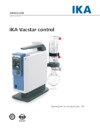
Two-position control:
IKA Vacstar digital in standalone operation
Vacuum created without a controller through simple suction, no
vacuum target value control possible.
The pump speed can be changed by manually setting the speed
using the rotating/pressing knob (C) of the vaccum pump.
1 Recipient (load, e.g. rotary evap-
orator, reactor)
2 Vacuum separator (e.g. Woulff
bottle)
5 Vacuum valve/ball valve
7 Emission condenser
Connection of interfaces
NOTE
Observe the relevant connections
(see Fig. 1).
O: Hose connection d= 8 mm OUTLET
Link this connection to the emission condenser with a vacuum
hose, or fit a sound absorber to the end.
NOTE
Put
the end
of the
hose in the
extractor hood!
Check there is a free outlet on the
pressurised side!
Do not
use a
throttle on the
pressurised side and do not close
the outlet! Connect the exhaust
line to this connection.
K: Connection for vacuum controller VC 10 (Mini DIN)
You can connect the vacuum pump and the vacuum controller
VC 10 or the rotary
evaporator
RV10 auto with the
analogue
connection cable MVP 10.100 for precise speed-controlled
vacuum
control.
The vacuum controller detects the pump and switches to
speed-vacuum control mode. Two-position control is deactivated.
Manual activation of the vacuum valve or ball valve.
Rough vacuum control is possible, for example, with the vacuum
control valves VCV 1 and VCV 2, by mixing in air from outside.
L: USB interface
Connect the vacuum pump IKA Vacstar digital to a PC with a USB
A - USB B cable. Any device software updates can be loaded using
the IKA FUT software tool.
M: RS 232 interface
You can connect the IKA Vacstar digital vacuum pump to a PC
using an RS 232 interface cable. The pump can be operated in
conjunction with other devices with
labworldsoft
®
laboratory
device software. For further information see the chapter “
Interfaces
and outputs”.
N: Water valve connection
Connect the
optional
water
throttle
valve
RV 10.5001
to the
diaphragm vacuum pump.
The water
flow
to the
emission
condensor is controlled using the water valve. The valve is opened
as soon as the pump is switched on.
I: Hose connection for suction line d= 8 mm INLET
Connect the suction line to this connection.
Link this connection to the recipient (rotary evaporator condenser,
laboratory reacor etc.) with a vacuum hose.
P: Power supply cable connection
Check that the voltage information on the rating plate matches
your mains supply.
Connect
the power supply cable to supply
electricity.
Содержание
- Ika vacstar digital p.1
- ليغشتلا تاميلعت p.1
- Geräteaufbau device setup p.2
- Zeichenerklärung p.5
- Warnung p.5
- Vorsicht p.5
- Konformitätserklärung p.5
- Inhaltsverzeichnis p.5
- Hinweis p.5
- Gewährleistung p.5
- Gefahr p.5
- Warnung p.6
- Flüssigkeiten p.6
- Verhindern sie das auftreten p.6
- Explosionsfähigen p.6
- Tragen p.6
- Einen sicheren zustand gefahren wird siehe p.6
- Sicherheitshinweise p.6
- Bedingungen p.6
- Schwerer p.6
- Arbeiten p.6
- Persönliche p.6
- Anwender sein stellen p.6
- Notfallmaßnahme p.6
- Abgasleitung p.6
- Mit einem nachgeschalteten p.6
- Mit dem in kapitel zubehör p.6
- Inbetriebnahme betriebsart p.6
- Inbetriebnahme p.6
- Hinweis p.6
- Gerät alle p.6
- Geknickt werden p.6
- Gefahrenklasse des zu p.6
- Zwischen medium und gerät können elektrostatische p.6
- Zulässige p.6
- Gefahr p.6
- Vorsicht p.7
- Rückschlagventile p.7
- Membran p.7
- Lüftungsschlitze p.7
- Lösemittelhaltige p.7
- Können p.7
- Hilfsmittel p.7
- Gerät verwendeten p.7
- Eingangs und p.7
- Betrieb p.7
- Beachten sie den zulässigen p.7
- Auspacken p.7
- Andere innenteile p.7
- Ablagerungen p.7
- Warnung p.7
- Wissenswertes p.8
- Warnung p.8
- Vorsicht p.8
- Hinweis p.8
- Gefahr p.8
- Bestimmungsgemäßer gebrauch p.8
- Pumpe sowohl p.9
- Membran vakuumpumpen p.9
- Hinweis p.9
- Hierbei oft p.9
- Erzeugen p.9
- Bewegungen der p.9
- Automatischen drehzahlgeregelten p.9
- Auto kan p.9
- Aufstellen p.9
- Zwei punkt regelun p.9
- Vakuumcontroller p.9
- Turbomolekularpumpen p.9
- Stelle mit der saugleitun p.9
- Sollwertabgleic p.9
- Schließe p.10
- Rotationsverdampfer p.10
- Hinweis p.10
- Drehzahl vakuumregel modus p.10
- Sollwertes p.11
- Rotationsverdampfer p.11
- Pumpgeschwindigkei p.11
- Hinweis p.11
- Erreiche p.11
- Einstellung p.11
- Aufgeführten p.12
- Technischen date p.12
- Inbetriebnahme p.12
- Hinweis p.12
- Hauptschalte p.12
- Geräte p.12
- Gerät nach einstecke p.12
- Einschalte p.12
- Displaysegmente p.12
- Betriebsar p.12
- Beendigun p.12
- Bedingunge p.12
- Beachte p.12
- Schnittstellen und ausgänge p.13
- Hinweis p.13
- Wartung und reinigung p.14
- Fehlermeldungen p.15
- Zubehör p.15
- Produktberührende teile p.15
- Technische daten p.16
- Warranty p.19
- Warning symbols p.19
- Warning p.19
- Declaration of conformity p.19
- Danger p.19
- Contents p.19
- Caution p.19
- Warning p.20
- Emergency p.20
- Temperature p.20
- Downstream p.20
- Safety instructions p.20
- Device p.20
- Release p.20
- Danger p.20
- Appropriate p.20
- Pumping process p.20
- Accordance p.20
- Prevent p.20
- Poisonous p.20
- Place where p.20
- Operation p.20
- Medium p.20
- Labelling p.20
- Instruction p.20
- Functioning p.20
- Explosive p.20
- Evacuated p.20
- Ensured p.20
- Warning p.21
- Unwante p.21
- Unpacking p.21
- Sufficient cooling p.21
- Replacement p.21
- Remove p.21
- Maintenanc p.21
- Entere p.21
- Condensation p.21
- Caution p.21
- Correct use p.22
- Contravention of p.22
- Caution p.22
- Capacity p.22
- Adjustable p.22
- Workin p.22
- A downstream p.22
- Warning p.22
- Useful information p.22
- Safety p.22
- Residentia p.22
- Release of p.22
- Protect p.22
- Process p.22
- Prevent p.22
- Device is p.22
- Danger p.22
- The pump and the operating p.23
- Setting up p.23
- Pressure p.23
- Entering p.23
- Connections p.23
- Throttle on the p.24
- Throttle p.24
- The end p.24
- Rv 10 001 p.24
- Optional p.24
- Labworld sof p.24
- Laboratory p.24
- Hose in the p.24
- Evaporator p.24
- Emission p.24
- Do not p.24
- Diaphragm vacuum pump p.24
- Connec p.24
- Analogue p.24
- Device configuration p.25
- Analogue connecting p.25
- Without p.25
- Recognitio p.25
- Commissioning p.26
- System p.27
- Selection p.27
- Namur commands and the additional ika specific p.27
- Labworld sof p.27
- Interfaces and outputs p.27
- Interfac p.27
- Floatin p.27
- Connected p.27
- Conjunctio p.27
- Comply p.27
- Command p.27
- Characteristic p.27
- Automation p.27
- Maintenance and cleaning p.28
- Product contact parts p.29
- Error codes p.29
- Accessories p.29
- Technical data p.30
- Table des matières p.33
- Remarque p.33
- Prudence p.33
- Garantie p.33
- Explication des symboles p.33
- Déclaration de conformité p.33
- Danger p.33
- Avertissement p.33
- Remarque p.34
- Conformément p.34
- Raccordez p.34
- Chapitre p.34
- Que seul p.34
- Attentivement p.34
- Protection p.34
- Poussières p.34
- Pour la santé de l utilisateur p.34
- Portez votre équipement de p.34
- Personnel p.34
- Mélanges p.34
- Vérifier p.34
- La sécurité du travail n est garantie qu en utilisant les p.34
- Veillez p.34
- L appareil p.34
- Vacstar digital p.34
- Exploitée exclusivement p.34
- Utilisés p.34
- Est ouverte p.34
- Utilisation avec les p.34
- Décrites p.34
- Travaille avec p.34
- Substances inflammables p.34
- Danger p.34
- Substances p.34
- Consignes de sécurité p.34
- Ouvrir p.35
- Outillage p.35
- L appareil p.35
- Habilité p.35
- Exclusivement p.35
- Déballage p.35
- Avertissement p.35
- Annes ou clapets antiretour dans la conduite d aspiration en cas d utilisation de plusieurs p.35
- Substances utilisées p.35
- Remontés p.35
- Remise p.35
- Prudence p.35
- Produit voir le chapitre p.35
- Personnel p.35
- Détection p.36
- Vacstar p.36
- De vide qui réduit la p.36
- Utilisation conforme p.36
- De rotation p.36
- Séparation p.36
- Si l appareil est utilisé sans respecter p.36
- De manière automatisée ainsi p.36
- Service p.36
- Danger p.36
- Remarque p.36
- D autres p.36
- Prudence p.36
- Contrôleur p.36
- Pression p.36
- Consignes p.36
- Pour protéger les soupapes p.36
- Combinaison p.36
- Permet p.36
- Adapté p.36
- Ou avec un évaporateur p.36
- Liquide ou du condensat p.36
- Le débit p.36
- Informations utiles p.36
- Générer p.36
- Exemple p.36
- Théorique p.37
- Solvants p.37
- Remarque p.37
- Installation p.37
- Fuite naturel p.37
- Flacon de woulf p.37
- Du condensat p.37
- Devant le raccord p.37
- Contrôleur p.37
- Combinaison p.37
- Automatique p.37
- Analogique p.37
- Remarque p.38
- Permet de charger p.38
- L outil logiciel p.38
- Remarque p.39
- Tirez sur la fiche secteur pour p.40
- Signalétique p.40
- Si la pompe est reliée au contrôleur de vide vc 10 ou à p.40
- Remarque p.40
- Mise en service p.40
- Indiquée p.40
- Appuyant simultanément p.40
- Labworld sof p.41
- La fonction p.41
- Globalement p.41
- Fonctionnement p.41
- En série p.41
- D interface entre l appareil p.41
- D automatisation p.41
- Communication p.41
- Universal serial bus p.41
- Caractéristiques p.41
- Transmission asynchrone p.41
- Système p.41
- Supplémentaires p.41
- Remote p.41
- Remarque p.41
- Ports et sorties p.41
- Mise à jour du p.41
- Entretien et nettoyage p.42
- Pièces en contact avec le produit p.43
- Messages d erreurs p.43
- Accessoires p.43
- Caractéristiques techniques p.44
- Garantía p.47
- Explicación de símbolos p.47
- Declaración de conformidad p.47
- Índice de contenido p.47
- Precaución p.47
- Peligro p.47
- Peligro p.48
- Advertencias de seguridad p.48
- Advertencia p.48
- Precaución p.49
- Desembalaje p.49
- Advertencia p.49
- Uso previsto p.50
- Precaución p.50
- Peligro p.50
- Información importante p.50
- Advertencia p.50
- Realizar una p.51
- Aspiración p.51
- Presenci p.51
- Aparecen p.51
- Nomina p.51
- Manguer p.51
- Líquido p.51
- Instalación p.51
- Indicación p.51
- Generador p.51
- Etiquetas p.51
- Distensió p.51
- Disolvent p.51
- Válvula p.51
- De regulación p.51
- Velocidad p.51
- Conforme p.51
- Una tasa p.51
- Siempre p.51
- Conectar siempre p.51
- Regulació p.51
- Conducto p.51
- Recipiente p.51
- Compensació p.51
- Giratorio pulsador p.52
- Asegúrese p.52
- Regulación de la velocidad p.53
- Controlador p.53
- Automáticamente p.53
- Por ejemplo p.54
- El modo de p.54
- Disponible p.54
- Desenchufe el p.54
- Condiciones p.54
- Todo en p.54
- Puesta en servicio p.54
- Universal usb p.55
- Través de la p.55
- Puede utilizarse en el p.55
- Longitud máxim p.55
- Labworld sof p.55
- Interfaces y salidas p.55
- Evacuación p.55
- Din 66022 p.55
- De inicio y p.55
- Caracteres p.55
- Mantenimiento y limpieza p.56
- Partes en contacto con el producto p.57
- Mensajes de error p.57
- Accesorios p.57
- Datos técnicos p.58
- Spiegazione dei simboli p.61
- Sommario p.61
- Pericolo p.61
- Garanzia p.61
- Dichiarazione di conformità p.61
- Cautela p.61
- Avvertenza p.61
- Nebulizzate p.62
- Danni alla salute dell utente p.62
- Condizioni p.62
- Collegamento p.62
- Classe p.62
- Avvertenze per la sicurezza p.62
- Avvertenza p.62
- Aria oppure p.62
- Senza apporto p.62
- Polveri p.62
- Pericolo p.62
- Sopra a un p.63
- Protezioni p.63
- Fissare mai la pompa p.63
- Essere p.63
- Dispositivi p.63
- Disimballo p.63
- Componenti p.63
- Circostanze p.63
- Cautela p.63
- Carico utilizzare valvole p.63
- Avvertenza p.63
- Cautela p.64
- Avvertenza p.64
- Uso conforme p.64
- Pericolo p.64
- Informazioni importanti p.64
- Temporale p.65
- Raggiunto p.65
- Pressione p.65
- Liberamente p.65
- Installazione p.65
- Impedisce p.65
- Funzionamento p.65
- Funziona p.65
- Flessibili inlet outlet e le p.65
- Eventualmente p.65
- Condensazione p.65
- Attacchi p.65
- Aspirazione p.65
- Versione p.65
- Un elevata durata p.65
- Pompa può p.66
- Modalità p.66
- Mediante p.66
- Interfaccia p.66
- Impostazione p.66
- Generazione del vuoto p.66
- Flessibile del p.66
- Flessibile p.66
- Emissioni p.66
- Dell evaporatore p.66
- Condensator p.66
- Collegare questo p.66
- Collegare p.66
- Attacco p.66
- Silenziatore p.66
- Pos 6 disponibile p.67
- Pompa viene arrestata p.67
- Opzione p.67
- Visualizzazione p.68
- Versione del software p.68
- Pulsante manopola p.68
- Operativo b risulta necessario in particolare p.68
- Messa in funzione p.68
- Manopo p.68
- Impostata p.68
- Garantito il funzionamento p.68
- Funzionamento p.68
- Contrari p.68
- Allo spegnimento p.68
- Accendendo p.68
- Trasferimento trasferimento asincrono p.69
- Se si verifica l evento wd1 viene disattivata la funzione di p.69
- Posteriore p.69
- Parametri p.69
- Operativo p.69
- Monitoraggio p.69
- L interfaccia p.69
- L apparecchio p.69
- Interfacce e uscite p.69
- Esclusivamente p.69
- E l aggiornamento del firmware con l ausilio del p.69
- Consente p.69
- Consecutivi p.69
- Comunicazione adeguati è possibile trasferire direttamente tali comandi all apparecchio p.69
- Watchdog su m 20 500 secondi p.69
- Comando p.69
- Watchdog questo comando avvia p.69
- Comandi p.69
- Manutenzione e pulizia p.70
- Parti a contatto con il prodotto p.71
- Messaggi di errore p.71
- Accessori p.71
- Dati tecnici p.72
- Условные обозначения p.75
- Содержание p.75
- Осторожно p.75
- Опасно p.75
- Декларация о соответствии стандартам p.75
- Гарантия p.75
- En 61326 p.75
- En 61010 1 en p.75
- Опасно p.76
- Указания по технике безопасности p.76
- Примечание p.76
- Шумоглушитель p.77
- Соединительный кабель mvp 10 00 p.77
- Сетевой кабель для подключения к портативному пк p.77
- Руководство по эксплуатации p.77
- Распаковка осторожно распакуйте прибор при наличии повреждений немедленно составьте соответствующий акт p.77
- Распаковка p.77
- Осторожно p.77
- Мембранный вакуумный насос p.77
- Комплект поставки p.77
- Гарантийный талон p.77
- Ika vacstar digita p.77
- Осторожно p.78
- Опасно p.78
- Использование по назначению p.78
- Полезная информация p.78
- Установка p.79
- Уменьшает свою p.79
- Создают вакуум p.79
- Ротационным p.79
- Регулирования p.79
- Примечание p.79
- Повышается вследствие естественной p.79
- Отработанного p.79
- Мощности откачки p.79
- Мембранные вакуумные p.79
- Достижении p.79
- Вращения p.79
- Включения вакуумного p.79
- Запрещается использовать p.80
- Вакуума vcv 1 и vcv 2 посредством p.80
- Ika vacstar digita p.80
- Табличке p.80
- Соединить p.80
- С мембранным p.80
- Регулирования p.80
- Примечание p.80
- Напряжения p.80
- Нагнетания p.80
- Имеющиеся p.80
- Вакуумным p.80
- Вакуумный p.80
- Конфигурация p.81
- Достижении p.81
- Возможна p.81
- Вакуумны p.81
- Ika vacstar digita p.81
- Системы p.81
- Работы регулирование p.81
- Примечание p.81
- При достижении заданного значения встроенный в p.81
- Опциональным p.81
- Настройка p.81
- Нагрузка например p.81
- Режиме p.82
- Примечание p.82
- Исчезновения напряжения p.82
- Гарантируется p.82
- Вытащите сетевой штекер из p.82
- Выполнении p.82
- Ввод в эксплуатацию p.82
- Безопасная p.82
- Автоматический p.82
- Штекера блока p.82
- Примечание p.83
- Интерфейсы и выходы p.83
- Техническое обслуживание и очистка p.84
- Сообщения об ошибках p.85
- Склянка вульфа комплект водяных клапанов vsw1 p.85
- Ремонтный комплект p.85
- Регулятор вакуума ika vc 10 клапаны регуляторы вакуума ika vcv 1 и vcv 2 обратный клапан ika vc 10 00 вакуумный шланг ika vh si кабель pc 1 rs 232 p.85
- Принадлежности p.85
- Если неисправность не устраняется описанными мерами или отображается другой код ошибки обратитесь в сервисную службу отправьте прибор производителю с кратким описанием неисправности p.85
- Другие принадлежности см на сайте www ika de p.85
- Детали контактирующие с продуктом p.85
- Возникающие ошибки отображаются на дисплее b с помощью соответствующих кодов например error 4 в этом случае выполните следующие действия выключите прибор с помощью выключателя примите меры по устранению неисправности снова включите прибор p.85
- Вакуумный предохранительный конденсатор паров vse 1 p.85
- Технические данные p.86
- Средние значения право на технические изменения сохраняется p.87
- Índice p.89
- Perigo p.89
- Garantia p.89
- Explicação dos símbolos p.89
- Declaração de conformidade p.89
- Cuidado p.89
- Perigo p.90
- Indicações de segurança p.90
- Materiais p.91
- Formação p.91
- Forma evita se p.91
- Desembalar p.91
- Cuidado p.91
- Condensação p.91
- Condensador p.91
- Utilização p.91
- Capítulo p.91
- Tomada p.91
- Sedimentações p.91
- Reduzida p.91
- Profissional p.91
- Produto p.91
- Peças p.91
- Nesse local p.91
- Nenhuma conexão p.91
- Uso adequado p.92
- Perigo p.92
- Observação p.92
- Informações p.92
- Cuidado p.92
- Arquimedes p.93
- Velocidade p.93
- Adaptadores p.93
- Regulagem p.93
- Recomendação p.93
- Operação silenciosa p.93
- Observação p.93
- Necessário p.93
- Montagem p.93
- Menores p.93
- Membrana p.93
- Mangueira p.93
- Líquidos p.93
- Interrompida p.93
- Executadas p.93
- Estabelece p.93
- Conexões p.93
- Acionamento p.94
- Velocidad p.94
- Software p.94
- Regulagem p.94
- Observação p.94
- Membrana p.94
- Giratório de pressã p.94
- Eventualmente p.94
- Velocidade da bomba p.95
- Reduzida p.95
- Operação p.95
- Observação p.95
- Condições p.96
- Colocação em operação p.96
- Armazenado p.96
- Alimentação p.96
- Acordo p.96
- Tensão p.96
- Procedimento p.96
- Principal d p.96
- Operação p.96
- Observe p.96
- Observação p.96
- Individual p.96
- Giratório de p.96
- Especificadas p.96
- Especialmente p.96
- Disponível quando estas p.96
- Individuais p.97
- De dados p.97
- É realizada por p.97
- Comunicação p.97
- É desligada p.97
- Aparelhos conectados p.97
- X0d hex 0x0a p.97
- Aparelho para o computador p.97
- Watchdog p.97
- Transferência transferência assíncrona p.97
- Transferência p.97
- Propriedades p.97
- Procedimento p.97
- Observação p.97
- O aparelho envia exclusivamente por solicitação do p.97
- Nível baixo p.97
- Norma din 66022 p.97
- Interrupção p.97
- Interfaces e saídas p.97
- Manutenção e limpeza p.98
- Acessórios p.99
- Separar p.99
- Peças em contato com o produto p.99
- Mensagens de erro p.99
- Dados técnicos p.100
- Wskazówka p.103
- Spis treści p.103
- Ostrożnie p.103
- Objaśnienie symboli p.103
- Gwarancja p.103
- Deklaracja zgodności p.103
- Zasady bezpieczeństwa p.104
- Wskazówka p.104
- Ostrzeżenie p.104
- Rozpakowanie p.105
- Ostrzeżenie p.105
- Ostrożnie p.105
- Wskazówka p.106
- Ważne informacje p.106
- Użycie zgodne z przeznaczeniem p.106
- Ostrzeżenie p.106
- Ostrożnie p.106
- Wykrywanie temperatury p.107
- Wskazówka p.107
- W kombinacji z regulatorem p.107
- Uszczelniane p.107
- Ustawienie p.107
- Prędkość p.107
- Próżniowe p.107
- Przewodzie ssawnym przed króćcem ssawnym p.107
- Odpowiednio p.107
- Możliwe p.107
- Membranowe pompy p.107
- Śrubowe pompy dyfuzyjne lub pompy p.107
- Zastosować p.107
- Wytworzenia p.107
- Wylotowego p.107
- Węża p.108
- Wyparkę obrotową rv 10 p.108
- Wskazówka p.108
- Vcv 1 i vcv p.108
- Sieciowy p.108
- Sieciowego podłączyć p.108
- Powietrza p.108
- Porównaniu p.108
- Poprowadzić p.108
- Dostępnego p.108
- Domieszkę obcego p.108
- Analogowym p.108
- Wskazówka p.109
- Ustawienie p.109
- Regulacja prędkości p.109
- Prędkość obrotowa p.109
- Próżniowym p.109
- Osiągnięciu wartości zadanej przewód ssawny zostanie p.109
- Osiągnięciu p.109
- Trybie pojedynczym lub dwupunktowym p.110
- Próżniowy p.110
- Przerwaniu zasilania p.110
- Przeciwnym p.110
- Połączeniu p.110
- Pokrętło przycisk c naciśnięcie p.110
- Mvp 10 00 z regulatorem próżni vc 10 lub p.110
- Eksploatowana p.110
- Automatycznego restartu p.110
- Z komputerem p.110
- Wskazówka p.110
- Urządzenia p.110
- Uruchomienie p.110
- Spontanicznie p.111
- Rozpoznane p.111
- Przewodów interfejsowych p.111
- Przestrzegać p.111
- Przenieść p.111
- Program alarmowy p.111
- Złącza i wyjścia p.111
- Połączeniem p.111
- Zresetować p.111
- Parametry następujące p.111
- Zainstalowany p.111
- Odpowiadają p.111
- Właściwości p.111
- Maksymaln p.111
- Wytwarzania p.111
- Komunikacji p.111
- Wystąpi zdarzenie p.111
- Alarmowego p.111
- Wskazówka p.111
- Urządzenia p.111
- Systemem automatyki p.111
- Spośród sygnałów p.111
- Konserwacja i czyszczenie p.112
- Wyposażenie p.113
- Komunikat o błędzie p.113
- Części stykające się z produktem p.113
- Dane techniczne p.114
- ةظحلام p.117
- هيبنت p.117
- نامضلا p.117
- ريذحتلا زومر p.117
- ريذحت p.117
- رطخ p.117
- تايوتحملا p.117
- ةقباطملا نلاعإ p.117
- ريذحت p.118
- رطخ p.118
- ةملاسلا تاميلعت p.118
- ةظحلا p.118
- هيبنت p.119
- ريذحت p.119
- تايوتحملا غيرفت p.119
- ةظحلام p.120
- ةديفم تامولعم p.120
- هيبنت p.120
- ريذحت p.120
- رطخ p.120
- حيحصلا مادختسلاا p.120
- ةظحلام p.121
- بيكرتلا p.121
- ةظحلام p.122
- ةظحلام p.123
- ليغشتلا ءدب p.124
- ةظحلام p.124
- تاجرخملاو تاهجاولا p.125
- ةظحلام p.125
- فيظنتلاو ةنايصلا p.126
- جتنملاب لاصتلاا ءازجأ p.127
- تاقحلملا p.127
- أطخلا زومر p.127
- ةينفلا تانايبلا p.128
- Uygunluk beyanı p.131
- Uyarı sembolleri p.131
- Tehli ke p.131
- I çindekiler p.131
- Garanti p.131
- Kurun egzoz p.132
- Kurulumunu p.132
- Hayvanlar üzerinde p.132
- Güvenlik talimatları p.132
- Güvenlik p.132
- Erişebileceğiz p.132
- Teknik veriler p.132
- Dirsekli p.132
- Tehli ke p.132
- Dengeli p.132
- Talimatlarını p.132
- Cihaz parçaları p.132
- Sıcaklığının altında p.132
- Buğusu buharlar tozlar veya p.132
- Solunması veya p.132
- Ortamlarla p.132
- Olmayan p.132
- Olarak p.132
- Maddelere p.132
- Kılavuzunun tamamını okuyun p.132
- Ile uyumlu p.133
- Güvenili p.133
- Giren istenmeyen sıvılar yüksüz p.133
- Gerçek p.133
- Bağlanmayacaksa makinenin güvenli p.133
- Ambalajdan çıkarma p.133
- Çalıştığından p.133
- Vakum pompası ika vacstar p.133
- Temas eden cihaz p.133
- Sırasında p.133
- Soğutma p.133
- Kısaltır p.133
- Tehli ke p.134
- Faydalı bilgiler p.134
- Doğru kullanım p.134
- Ulaştığında p.135
- Sistemdeki sızıntının p.135
- Pompa haznesindeki sıvılar p.135
- Kontrollü hızla otomatik çalışmada pompa p.135
- Kapatıldığında belirlenen p.135
- Bağlamda p.135
- Ayarlama p.135
- Özelliklerini p.135
- Pompasını p.136
- Plakasındaki p.136
- Kontrolü p.136
- Hortumuna p.136
- Gerilimine p.136
- Döndürme basma p.136
- Bilgisinin p.136
- Basınçlı tarafta gaz kelebeği p.136
- Durdurmak p.138
- Devreye alma p.138
- Başlatmak p.138
- Bağlantısını p.138
- Bağlantı p.138
- B cihazın p.138
- Aracılığıyla p.138
- Üzerinde p.138
- Özellikle p.138
- Topraklanmış p.138
- Soketinden p.138
- Otomatik p.138
- Modunda p.138
- Kullanılan p.138
- Kesildikten p.138
- Erdiğinde p.138
- Düğmesine c basarken p.138
- Arayüzler ve çıkışlar p.139
- Bakım ve temizlik p.140
- Ürün temas parçaları p.141
- Hata kodları p.141
- Aksesuarlar p.141
- Teknik veriler p.142
- Www ika com p.144
Похожие устройства
-
 IKA MVP 10 basic 0003980000Технический паспорт
 -
 IKA MVP 10 basic 0003980000Руководство по эксплуатации
 -
 IKA VACSTAR digital 0020016236Флаер
 -
 IKA VACSTAR digital 0020016236Технический паспорт
 -
IKA VACSTAR control 0020019065Флаер
-
 IKA VACSTAR control 0020019065Технический паспорт
 -
 IKA VACSTAR control 0020019065Руководство по эксплуатации
 -
 STATUS VP 159102Руководство по эксплуатации
 -
 Super-Ego SEGO RECV 1500001400Инструкция
 -
 Super-Ego SEGO VAC 6.0 1500001501Инструкция
 -
Super-Ego SEGO VAC 3.0 R32 1500002663Инструкция
-
Super-Ego SEGO VAC 3.0 1500001399Инструкция
Узнайте, как правильно настроить вакуумный насос для лабораторных устройств. Подробные инструкции по подключению и управлению для эффективной работы.