
Ridgid 605/608M 38038 Инструкция по эксплуатации онлайн
600 Hand Tube Bender Instruction Sheet
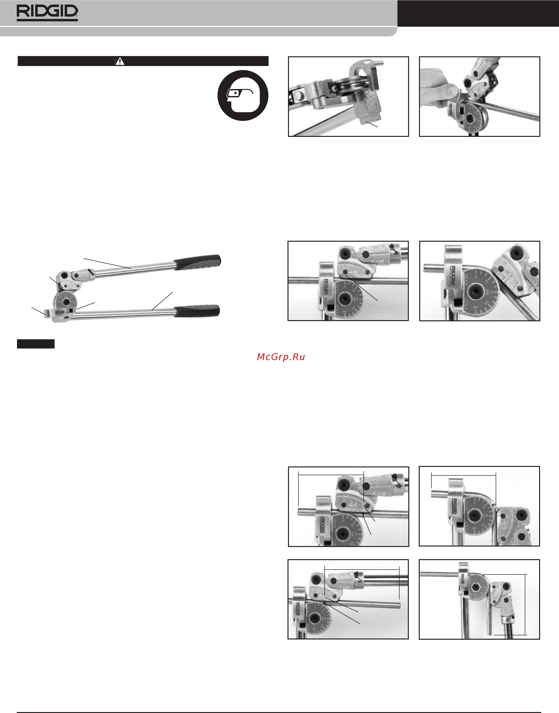
Figure 2 – Vise Mounting Point Figure 3
2. Move Carriage Handle and Tube Latch away from Form.
3. Position tubing in Form groove and secure tubing in Form with
Latch (Figure 3).
4. Lower Carriage Handle until the “0” Line on the Carriage aligns with
the 0° designation on the Form (Figure 4).
5. Rotate the Carriage Handle around the Form until the “0” Line on the
Carriage aligns with the desired degree of bend on the Form (Figure
5).
Figure 4 Figure 5
Measured Bends Relative to Other
Features (Tube ends, Bends, etc.)
For 90° Bends:
• Mark the tube at the desired distance (X) from the feature (end of
tube, bend, etc.). The center of the leg of the bend will be this dis-
tance from the feature.
• Place the tube in the bender as described in Steps 1-5 above.
• If the feature is to the LEFT of the mark (see Figure 6 – Before),
align the mark on the tube with the “L” line on the Carriage.
• If the feature is to the RIGHT of the mark (see Figure 8 – Before),
align the mark on the tube with the “R” line on the Carriage.
Figure 6 – Before Figure 7 – After
Figure 8 – Before Figure 9 – After
• With the mark on the tube appropriately aligned, move the Carriage
so that the “0” Line aligns with the 90 degree line on the Form. (See
Figures 7 and 9 – After).
WARNING
Read these instructions and the warnings and
i
nstructions for all equipment being used before
using to reduce the risk of serious personal injury.
• Always use safety glasses to reduce the risk of
e
ye injury.
•
Do not use handle extensions (such as a piece
of pipe). Han dle extensions can slip or come off and increase
t
he risk of serious injury.
If you have any question concerning this RIDGID
®
product:
– Contact your local RIDGID distributor.
– Visit www.RIDGID.com or www.RIDGID.eu to find your local RIDGID
contact point.
– Contact Ridge Tool Technical Services Department at rtctechser-
vices@em erson.com, or in the U.S. and Canada call (800) 519-3456.
The RIDGID
®
600 series lever benders are designed to easily bend
materials such as copper, steel, stainless steel and other hard metal
tube to a maximum of 180°. Built-in rollers and a heavy-duty handle
design combine to produce high quality bends with greatly reduced
effort when compared to conventional benders.
Figure 1 – 600 Series Bender
Selection of appropriate materials and installation, joining
and forming methods is the responsibility of the system designer and/or
installer. Selection of improper materials and methods could cause sys-
tem failure.
Stainless steel and other corrosion resistant materials can be contami-
nated during installation, joining and forming. This contamination could
cause corrosion and premature failure. Careful evaluation of materials
and methods for the specific service conditions, including chemical and
temperature, should be completed before any installation is attempted.
Inspection/Maintenance
The bender should be inspected before each use for wear or damage
that could affect safe use. Clean as needed to aid inspection and to pre-
vent handles and controls from slipping from your grip during use.
Make sure the bender is complete and properly assembled. If any prob-
lems are found, do not use until the problems are corrected. Lubricate
all moving parts/joints as needed with a light lubricating oil, and wipe
any excess oil from the bender.
Operation
The 600 Series Lever Benders can be used either hand held or with the
bender mounted in a vise. Vise mounting is especially useful when
bending hard or thick walled materials.
Spring Back
All tubing will exhibit spring back after a bend is completed. Softer tub-
ing, such as copper, will have less spring back than harder tubing, such
as stainless steel. Experience will help you predict the amount of spring
back. Depending on tubing material and hardness, expect to overbend
approximately 1° to 3° to compensate for spring back.
General Operating Instruction
1. Grasp bender by the Form Handle or mount the bender in vise.
(Figure 2).
C
arriage Handle
T
ube
L
atch
F
orm Handle
NOTICE
F
orm
C
arriage
Grip In
Vise
Mark On
Tube
X
L Line
X
0 Line
X
Mark On
Tube
R Line
X
Printed 12/15
EC38632
999-999-403.09
REV. C
©2011, 2015, RIDGID, Inc.
The Emerson logo and RIDGID logo are registered trademarks of Emerson Electric Co. or RIDGID, Inc. in the U.S. and other countries.
All other trademarks belong to their respective holders.
Содержание
- For 90 bends 1
- General operating instruction 1
- Hand tube bender instruction sheet 1
- Inspection maintenance 1
- Measured bends relative to other features tube ends bends etc 1
- Operation 1
- Spring back 1
- Adjustment gain calculations 2
- Bend adjustment chart 2
- Bender specification 2
- Cintreuse manuelle n 600 fiche d utilisation 2
- For 45 bends 2
- Hand tube bender instruction sheet 2
- Making bends 90 to 180 2
- Reference mark 2
- Supporting products recommendation 2
- Cintrages mesurés à partir d éléments existants raccords coudes etc 3
- Coudes à 45 3
- Coudes à 90 3
- Effet ressort 3
- Fonctionnement 3
- Hand tube bender instruction sheet 3
- Inspection et entretien 3
- Mode d emploi 3
- Calcul de la longueur de tuyau nécessaire 4
- Caractéristiques des cintreuses 4
- Coudes de 90 à 180 4
- Hand tube bender instruction sheet 4
- Modo de empleo doblatubos manual serie 600 4
- Produits associés 4
- Reference mark 4
- Tableau de calcul de longueur 4
- Curvaturas de 90 5
- Funcionamiento 5
- Hand tube bender instruction sheet 5
- Inspección y mantenimiento 5
- Instrucciones de funcionamiento 5
- Retorno elástico 5
- Ubicación del centro de la curvatura en relación con un punto de referencia en el tubo un extremo codo etc 5
- Curvaturas de 45 6
- Curvaturas de entre 90 y 180 6
- Cálculo de ajustes ganancias 6
- Especificaciones de las doblatubos 6
- Hand tube bender instruction sheet 6
- Productos secundarios recomendados 6
- Reference mark 6
- Tabla de ajustes de curvaturas 6
- Curvas medidas em relação a outras características extremidades do cano curvas etc 7
- Efeito de retorno 7
- Folha de instruçõ da encurvadora manual de tubos 600 7
- Hand tube bender instruction sheet 7
- Inspeção manutenção 7
- Instrução operacional geral 7
- Operação 7
- Para curvas de 90 7
- Cálculos de ajuste ganho 8
- Especificação da encurvadora 8
- Execução de curvas de 90 a 180 8
- Hand tube bender instruction sheet 8
- Para curvas de 45 8
- Quadro de ajuste de curvas 8
- Recomendação para produtos de apoio 8
- Reference mark 8
- Gięcia mierzone od innych cech końców rury zagięć itp 9
- Gięcie 90 9
- Hand tube bender instruction sheet 9
- Instrukcja ręcznej giętarki do rur serii 600 9
- Obsługa 9
- Ogólna instrukcja obsługi 9
- Przeglądy konserwacja 9
- Sprężynowanie 9
- Dane techniczne giętarki 10
- Gięcie 45 10
- Gięcie pod kątem 90 do 180 10
- Hand tube bender instruction sheet 10
- Handrohrbiegezange anleitung 10
- Lesen sie vor der anwendung diese anleitung und warnungen sowie die anleitung für alle verwende ten geräte um das risiko schwerer verletzungen zu reduzieren tragen sie grundsätzlich eine schutzbrille um das risiko von augenverletzungen zu mindern verwenden sie keine griffverlängerungen etwa rohrstücke griffverlängerungen können abrutschen oder sich lösen und das risiko schwerer verletzungen erhöhen 10
- Obliczenia korekty przyrostu 10
- Reference mark 10
- Tabela korekty gięcia 10
- Zalecane produkty pomocnicze 10
- Średn zewn 10
- Średn zewn rury 10
- Allgemeine anleitung 11
- Anwendung 11
- Für 90 biegungen 11
- Gemessene biegungen in bezug zu anderen merkmalen rohrenden biegungen usw 11
- Hand tube bender instruction sheet 11
- Kontrolle wartung 11
- Rückfedern 11
- Biegeeinstellungstabelle 12
- Biegezangenspezifikation 12
- Einstellungsberechnungen biegewinkel 12
- Empfehlung unterstützender produkte 12
- Für 45 biegungen 12
- Hand tube bender instruction sheet 12
- Herstellen von biegungen mit 90 bis 180 12
- Reference mark 12
- Hand tube bender instruction sheet 13
- Инструкция на ручной трубогиб серии 600 13
- Общая инструкция по эксплуатации 13
- Осмотр обслуживание 13
- Расчет положения изгиба относительно других элементов концов трубы изгибов и пр 13
- Функционирование 13
- Hand tube bender instruction sheet 14
- Гибка на угол от 90 до 180 14
- Для изгибов на 45 14
- Радиус гиб 14
- Размер труб 14
- Расчет поправки коэффициента 14
- Таблица поправок при гибке 14
- Hand tube bender instruction sheet 15
- Рекомендации по использованию дополнительного оборудования 15
- Технические характеристики трубогиба 15
Похожие устройства
- Ridgid 604 38033 Инструкция по эксплуатации
- Ridgid 37428 Инструкция по эксплуатации
- Ridgid DM-100 37423 Инструкция по эксплуатации
- Ridgid CA-150 36848 Инструкция по эксплуатации
- Ridgid 1224 26107 Инструкция по эксплуатации
- Ridgid 3812S 16411 Инструкция по эксплуатации
- Orbis DICROMAT 2+ CR OB134612 Инструкция по эксплуатации
- Orbis CIRCUMAT PRO CR 12м OB134920 Инструкция по эксплуатации
- Orbis CIRCUMAT PRO CR OB134912 Инструкция по эксплуатации
- Orbis ECOMAT MINI OB135012 Инструкция по эксплуатации
- Orbis ORBIMAT OB132612 Инструкция по эксплуатации
- Orbis CIRCUMAT+ OB137112 Инструкция по эксплуатации
- Orbis DICROMAT MICRO OB133612 Инструкция по эксплуатации
- Orbis DICROMAT MINI OB133512 Инструкция по эксплуатации
- Orbis PROXIMAT PRO CR 360 OB134812 Инструкция по эксплуатации
- Orbis T-16G (OB060100) Инструкция по эксплуатации
- Orbis T-16 (OB060131) Инструкция по эксплуатации
- Orbis MINI T QRD (OB251232) Инструкция по эксплуатации
- Orbis MINI T D (OB251032) Инструкция по эксплуатации
- Orbis ALPHA QRD (OB270123) Инструкция по эксплуатации